Transformers are devices used to convert one of the parameters of electricity - voltage or current.
They belong to passive electrical devices, that is, they do not generate, but consume energy, so the current power in transformers cannot increase.
Thus, all transformers, depending on the converted parameter of electrical energy, are divided into 2 types :
- electric current transformers;
- electrical voltage transformers.
The operation of any electrical transformer is based on the principle of electromagnetic mutual induction - the ability of a current-carrying conductor to induce an emf in an adjacent conductor. The conductors in the transformer are the primary (input) and secondary (output) windings, wound on a magnetic circuit to strengthen the magnetic connection between them. The magnetic core is a closed or open core made of iron or a composite alloy with high magnetic permeability.
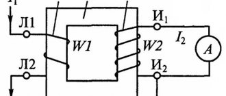
The main indicators of a transformer are the voltage and current transformation ratios:
КU=U2/U1 and KI=I2/I1
where U1,2 is the voltage in the primary and secondary windings, I1,2 is the current in the primary and secondary windings. They show how many times the input current or voltage at the transformer output changes. Depending on the value of the transformation ratio, step-up (K˃1) and step-down (K<1) transformers are distinguished. If the magnetic coupling between the windings does not change, then the transformation ratio will be equal to the ratio of the number of turns in the secondary and primary windings
K=w2/w1.
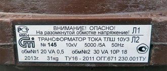
Explanation of device abbreviations
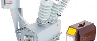
They also differ in the method of insulation: dry, cast and oil. Each has its own letter designation for the transformer. There are different voltage classes, such as ntmi-10, nom-10, znom-35, nom-35, NKF-110, nami-10. In the previous sentence, the numbers indicate the rated voltage. Let's start with the most important letter, which is at the very beginning of almost all abbreviations, this is the letter N. It just means a voltage transformer. By the way, it is simply called TN for short.
The next letters on the list and in importance are T and O, which indicate the number of phases. Three-phase and single-phase respectively. The letter T has another meaning, it means that the transformer has three windings. The following letters refer to insulation and cooling methods. It can be cast (L), C dry, Natural mental cooling, marked with the letter M.
The following values can be classified as additional functions. To connect measuring instruments, apply (I). If we see (K), we should understand that the voltage transformer has an additional winding that reduces the angular error or cascade. “Z” – presence of a grounding terminal. The active part is often placed in a porcelain cover, which is why the “F” symbol is present. (U) - refers to installations in moderate climates. D, E – divider, has a certain capacity.
Decoding abbreviations.
Types and their features
In addition to the step-down and step-up devices discussed above, other models are also available:
- traction;
- laboratory ones, in which it is possible to regulate the voltage;
- for rectifier installations;
- power supplies for radio equipment.
All of them belong to one large group of transformers - power ones. There is another type of such equipment. These are devices used to connect various electrical measuring instruments to high voltage circuits. They are called voltage measuring transformers. These devices are also widely used in electric welding. They also differ in design. Depending on this, two and multi-winding current and voltage measuring transformers are distinguished. Such devices are used for carrying out measurements and powering automation circuits and relay protection. They can be single- or three-phase with oil or air cooling.
It will be interesting➡ What is a transformer?
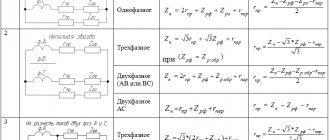
The classification and shape of the magnetic circuit also influences. He can be:
- core;
- armored;
- toroidal.
In this case, two types of winding designs are distinguished:
- Concentric;
- Disk.
According to the accuracy class, devices are divided into 4 categories:
- 0,2;
- 0,5;
- 1,0;
Another parameter that influences the specific application of current and voltage measuring transformers is the installation method. Depending on it, products are of the following types:
- internal;
- external;
- for switchgear.
Types of transformers.
Diversity
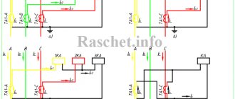
There are many types of current transformers, but in the most general terms, when choosing current transformers, it is taken into account that products are divided into measuring (TTI) and protective
| Separation factor | Views |
| Business date, meeting |
|
| Design | In the winding, the primary winding is connected in series with the conductor being measured. In toroidal ones, in its place there is a mesh (in the TA hole), and in rod ones, in its role it is a chain cable, which is equivalent to 1 turn. |
| Assembly |
|
| Number of laps |
|
| Insulation |
|
| Steps | One or more (cascade) |
| Under what name | Up to 1 kV and higher (for example, for current 10 kV) |
The current transformer can be configured to be opened, installed and locked, without shutting down, in online mode.
TT protective
Protection transformers are usually relay, they “look” so that the manipulator included in the electrical network of the power plant does not receive a fatal blow. Within electrical systems that create, transport and distribute energy, there are dangerous values for proper operation. But any equipment must be checked, repaired, repaired so that there remains a safety “window” in the form of TT for repair specialists.
CT Measurement
The purpose of the TTI instrument current transformer is to convert values, allowing you to connect a voltmeter, ammeter, or another meter without fear that it will burn out from excessive load. This produces the most accurate and reliable measurement data. In other words, TT isolates the connected device not only for measurements, but also any other device if necessary, from high power.
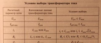
Equipment selection criteria
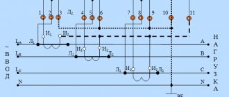
A voltage transformer consists of two windings and a core. Windings are also divided into primary and secondary. This is where the differences begin when comparing a voltage transformer with a current transformer. The primary winding of a voltage transformer contains significantly more turns than the secondary winding.
A voltage is applied to the primary winding, which we need to measure, and a voltmeter is connected to the secondary winding. Usually, when purchasing equipment, it is not its basic parameters that are taken into account. For a transformer these are:
- winding voltages, which are indicated on the panel;
- transformation ratio;
- angular error.
Interesting material to familiarize yourself with: what you need to know about the design of a power transformer.
It is also necessary to focus on operating conditions. Therefore, the most important parameters when choosing are the load, scope of application and short-circuit voltage of the transformer. At the first stage, it is necessary to make sure that the model’s power will be sufficient to cope not only with the task at hand, but also with possible overloads. It’s a good idea to have a device whose parameters can be changed during operation.
But focusing only on these characteristics is unacceptable. Since for the efficient operation of a 110 kV voltage transformer its technical characteristics are also important:
- current frequency;
- phasicity;
- installation method;
- location;
- load.
In addition, you need to determine whether the price of the device is right for you, as well as the cost of its further maintenance. The parameters for selecting current transformers are given in the table below.
Current transformer selection table.
Types of designs
Instrument current transformers are available in various types. They all have the same purpose, but differ in their constituent elements and operating principle. Each variety is used to achieve certain goals, which allows you to choose the best option for each case.
Reel type
This type of instrument transformers is considered the simplest in design. It gained its popularity back in Soviet times, when there were no better and more efficient devices. The reel device consists of the following elements:
- protective housing;
- secondary and primary winding;
- terminal block;
- contacts;
- figure-of-eight or loop winding.
These include:
- low discharge voltage, which is a consequence of weak coil insulation;
- possibility of use only at low rated voltages (no more than 3 kV);
- ability to work only with reduced electrical strength requirements.
Pass-through transformer
These devices are considered the most commonly used. They are widely used in various switchgear designed for voltages from 6 to 35 kV. Their device is not particularly complicated.
The structure consists of the following parts:
- cast epoxy body;
- magnetic circuit;
- primary winding;
- secondary winding.
Transformers of this type are valued because they make it possible to save bushing in closed switchgears. Other advantages of the device include:
- small dimensions;
- high electrodynamic resistance.
Rod device
Rod transformers are often called single-turn transformers. Their main feature is that the accuracy increases with increasing current and decreases with decreasing current. It is due to the fact that the primary winding passes through the core hole only once, which leads to numerical equality in the number of ampere-turns and rated current.
The device consists of the following parts:
- iron magnetic circuit (core);
- bushing rod;
- secondary and primary winding.
Tire device
Bus transformers are products whose design includes cores with a secondary winding, but no primary winding. There is a special hole in the main insulation of the device through which the switchgear bus is passed, which acts as the primary winding.
This type of transformer is very similar to the rod type. Only at low voltage readings are several turns of the conductor laid through the hole in the core, which makes it possible to obtain a multi-turn design of the device.
The main advantages of a bus transformer are:
- simplicity of design;
- ease of installation, repair and maintenance work;
- the ability to use the device not only at low rated currents, but also at high ones (more than 2 thousand amperes);
- high electrodynamic resistance due to the stability of the bus structure.
How does it work
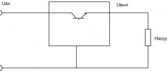
After an alternating voltage U1 appears in the primary winding, an alternating magnetic flux Ф appears in the magnetic circuit, which excites voltage in the secondary winding U2. This is the simplest and most concise description of the operating principle of a voltage transformer. The most important parameter of transformers is the “transformation ratio” and is denoted by the Latin “n”. It is calculated by dividing the voltage in the primary winding by the voltage in the secondary winding or the number of turns in the first coil by the number of turns in the second coil.
This coefficient allows you to calculate the required parameters of your transformer for the selected device. For example, if the primary winding has 2000 turns and the secondary winding has 100 turns, then n=20. With a network voltage of 240 volts, the output of the device should be 12 volts. You can also determine the number of turns at given input and output voltages.
Voltage transformers: purpose and principle of operation
A transformer is an electrical device. Converts alternating current of one voltage into electric current of another voltage. The frequency, according to the phenomenon of electromagnetic induction, remains unchanged.
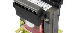
A static transformer consists of:
- primary and secondary windings;
- core.
The device is used in different power circuits and electrical appliances. Transmits electricity over long distances and:
- reduces energy losses;
- reduces the cross-sectional area of power transmission line wires.
Types of device:
- increasing;
- downward;
- power;
- rotating;
- pulse;
- dividing;
- coordinating
A step-down transformer is used in everyday life. It is through it that current passes and enters home sockets with a power of 220 W.
A power unit consisting of a core and several windings converts voltage into electrical circuits using the principle of electromagnetic induction. Also the value of AC voltage without changing its frequency. Used for distribution and transmission of electrical energy. The voltage in the windings is over 300 kV. Power – from 4 kV to 200,000 kVA.
Reference! The transformer is used to lower or increase alternating voltage. The basis is a ferromagnetic core. In addition, for uninterrupted operation - windings, insulation, magnetic circuit, cooling system.
The windings are made of insulated copper wires of rectangular cross-section. Between their layers there are voids for the circulation of cooling oil. The role of which is to take heat from the windings and transfer it through the radiator tubes to the environment.
The operating principle of the device is based on:
- change in magnetic flux;
- creating electromagnetic induction when passing through the winding;
- supplying voltage to the primary winding;
- reproduction of magnetism by an electric current that changes over time.
Alternating current flowing through the primary winding begins to create a magnetic current in the magnetic circuit. Gradually leads to flux in all windings, transforming the galvanic isolation (alternating voltage), but without changing the frequency.
Worth knowing! The operation of the device is based on electromagnetic induction. Due to alternating current, an alternating magnetic field is formed around the conductor and is modified into an electromotive force. The output voltage completely depends on the transformer used (step-down, step-up). The EMF coefficient in the windings is directly proportional to the number of turns.
What is the difference
By definition, these devices are designed to work with different electrical quantities as basic ones and, accordingly, the switching circuits will be different. For example, a current transformer is powered by a current source and does not work, and may even fail, if its windings are not loaded and no electric current flows through them. A voltage transformer is powered by voltage sources and, conversely, cannot operate for a long time at high current loads.
It will be interesting➡ What are isolation transformers
Selecting a current transformer for metering devices
The purpose of a commercial measuring transformer is to keep track of electricity. When choosing such models, pay attention to the following:
- Unom TT – 0.66 kV;
- accuracy class - 0.5 S for the market version, for technical control - 1.0;
- I1н – rated primary current.
The transformation ratio depends on the rated primary current.
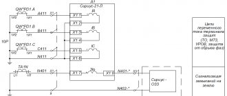
Not a single electrical substation can operate without current transformers. These devices work to know and take into account the current load. They provide protection for power circuits and provide timely signals about all changes in current strength in the primary circuit. A properly selected CT will serve without any complaints for a long time.
Instrument transformers
When operating equipment with high operating voltages and high current consumption, the question of their measurement and control arises. This is where instrument transformers come to the rescue. They provide galvanic isolation of measuring equipment from circuits with increased danger and reduce the measured value to the level required for measurements.
Before buying a voltage transformer, you need to analyze all the requirements for the device. It is necessary to take into account not only operating voltages, but also load currents when using a transformer in various devices.
You can make voltage transformers yourself, but if you need a simple household transformer with a voltage of 220 volts and a step down to 12 volts, then it is better to purchase one. You can find out how much voltage transformers cost on any website; as a rule, prices for household step-down voltage transformers are not very high.
Material on the topic: how a toroidal transformer works and what are its advantages.
Ferroresonance and methods of protection against it
A ferroresonant circuit in a network with an isolated neutral is a zero-sequence circuit with a nonlinear magnetization characteristic. A three-phase grounded voltage transformer, by design, consists of three single-phase transformers connected in a star/star configuration with a separate magnetic system. During overvoltages in the network, the induction in the magnetic circuit increases by at least 1.73 times.
In such modes, saturation of the magnetic circuit is possible and, as a consequence, the occurrence of ferroresonance in the network. According to energy supply services, every year 7–9% of voltage transformers are damaged in operation due to ferroresonance.
There are many ways to protect VTs from resonance phenomena in the network:
- production of VT with the most reduced working induction;
- inclusion of additional damping resistances in the HV and LV circuit;
- production of three-phase voltage transformers with a single magnetic system in a five-rod design;
- the use of special devices included in the open delta circuit;
- grounding the neutral of a three-phase voltage transformer through a current-limiting reactor;
- use of special compensation windings, etc.;
- the use of special relay circuits to protect the HV winding from overcurrents.
All these measures protect the voltage measuring transformer to one degree or another, but do not solve the problem fundamentally.
Service
It is necessary to pay attention that if the mode and operating conditions are observed, the ratings are correctly selected and regular maintenance, the CT will serve for 30 years or more. To do this you need:
Pay attention to various types of faults; note that most of them can be detected by visual inspection. Monitor the load in the primary circuits and prevent overload above the established norm. It is necessary to monitor the condition of the primary circuit contacts (if any) and there should be no external signs of damage. Equally important is monitoring the condition of the external insulation; in almost half of the cases, its resistance is impaired due to the accumulation of dirt or moisture, which short-circuits the contacts to the ground. For oil transformers, check the oil level, its cleanliness, presence of leaks, etc. Maintenance of such installations is practically not very different from other power plants, for example, NDE capacitive transformers; the difference lies in small technical details. CT verification must be carried out in accordance with current standards (GOST 8.217 2003). If a malfunction is detected, the device is replaced
The damaged CT is sent for repair, which is carried out by specialized services.
Grounded devices
Grounded voltage transformers are used in networks with an isolated neutral. Grounding the VT neutral makes it possible to monitor the network insulation using additional secondary windings connected in a star/delta configuration. In our opinion, this is the main function of grounded transformers; the measurement and accounting function is additional.
Often, grounded voltage transformers are used in electrical networks, in which protective windings are not used. The use of grounded transformers without using the network insulation control function is an unjustified risk. This is due to the fact that:
- grounded voltage transformers are susceptible to ferroresonance phenomena;
- The insulation of the HV winding cannot be tested under operating conditions with an applied one-minute power frequency voltage.
It will be interesting➡ Design and circuit of a three-phase transformer
Ungrounded devices
To resolve all issues related to the operation of grounded voltage transformers in networks with an isolated neutral, our company has developed a new three-phase group. Three-phase 3xNOL.08-6(10)M group, consisting of three ungrounded transformers connected in a delta/delta circuit. The main advantage of 3xNOL.08-6(10)M is the absence of a grounded terminal with weakened insulation.
This means that the transformer is not affected by ferroresonance and does not require additional protection against its influence. It is also possible to test the insulation of this transformer by applying a one-minute voltage at industrial frequency under operating conditions, since in this case there is no need for a high-frequency source.
Interesting material for review: useful information about current transformers.
Ungrounded transformers do not have high-voltage terminals with weakened insulation, which will also allow you to avoid violations that often occur in operation when determining the insulation resistance of the “X” terminal, since there are discrepancies in the regulatory documentation. Today, a large number of commercial metering points (PKU) include grounded voltage transformers with built-in fuses (ZNOLP). In case of single-phase ground faults, and as mentioned above, they happen quite often in overhead distribution networks, the built-in protective safety device (PSD) is triggered. The built-in protection device is primarily designed to protect the voltage transformer from short circuits in secondary circuits.
Since the fuse operation current is quite small, the voltage transformer is switched off in case of various overvoltages, including those caused by single-phase ground faults. The ZPU protects the HV winding from overcurrents, which are possible due to various technological disturbances in electrical networks. When the fuse trips, there will be no electricity metering. To restore accounting, it is necessary to replace the fuse-link ZPU.
Faraday's law
According to the law of electromagnetic induction, an EMF voltage is created in the secondary winding. Calculated using the formula – U2 = −N2*dΦ/dt.
Reference! Faraday is the fundamental law of electrodynamics. It states that the generated electromotive force is equal to the rate of change of magnetic flux, but taken with a minus sign. It was Michael Faraday who made the discovery when, during experiments, he announced that electromotive force begins to appear in a conductor only when the magnetic field changes. The magnitude of this force is directly proportional to the rate of change of the magnetic field.
All the facts are contained in one equation. However, the minus sign in the law is Lenz’s rule, indicating the occurrence of an inductive electric current when the magnetic field in the conductor changes. The action of the current is directed towards the magnetic field, which begins to counteract the change in magnetic flux.
Lenz's rule does not obey the laws of electrodynamics, because induction current appears both in windings and in solid metal blocks.
Repair of equipment
As for repair work, the device must be disconnected from the network to carry it out. It is prohibited to operate a transformer with an ungrounded base, and all faults must be repaired by specialists. Serviceable equipment produces a uniform sound during operation without crackling or sharp noises. In addition, resonant voltage increases occur in networks up to 10 kV. The reason for their appearance is considered to be multiple capacitance discharges resulting from an arc fault. This in turn leads to the formation of ferroresonance in the voltage transformer and its failure. This can be avoided by grounding the neutral through a resistor.