The rotor is an important component of many machines and mechanisms. The most important part denoted by this concept is the so-called armature of an electric motor or alternating current generators. Just like the wheel, the invention and use of the rotor allowed humanity to take a huge step towards electrification. More details about what a rotor is, what mechanisms and machines it is used in, and what types it comes in will be discussed in this article.
Rotor
Definition
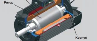
From the point of view of electrical engineering, a classic rotor is a rotating cylindrical body with the following structure:
- Shaft made of durable tool steel with at least two bearings, one each at the front and rear;
- Cores made of thick metal plates;
- Coils wound on cores assembled from plates;
- A collector or a pair of special conductive rings.
For forced air cooling of a part rotating very often at high speed, an impeller located at one of its ends is used. In generators, rotation is transmitted to the rotor from a turbine connected to it through a common shaft, or from a running engine using a pulley on which a flexible and durable belt is worn (V-belt drive).
So, the main function of the rotor is rotation relative to the stationary part. In electrical engineering, such a stationary part is the stator. Together, the rotor and stator are the most important components of electric motors and alternators.
Start
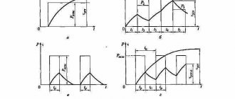
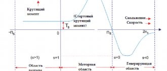
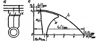
In asynchronous motors with a high moment of inertia, it is necessary to increase the torque while simultaneously limiting the starting currents - motors with wound rotors are used for these purposes. To increase the initial starting torque, a three-phase rheostat is included in the rotor circuit.
At the beginning of the start, it is fully introduced, and the starting current decreases. During operation, the rheostat is completely withdrawn. To start asynchronous motors with a squirrel-cage rotor, three schemes are used: with a reluctance coil, with an autotransformer and with switching from star to delta. The switch connects the reluctance coil and the motor stator in series.
How to start a three-phase asynchronous motor
When the rotor speed approaches the nominal speed, the switch closes, it short-circuits the coil and the stator switches to full mains voltage. During autotransformer starting, as the engine accelerates, the autotransformer is moved to the operating position in which the full mains voltage is supplied to the stator. Starting an asynchronous motor with the stator winding first turned on by star and then switched to delta gives a threefold reduction in current.
If the insulation of the frame and casings of electrical machines and transformers are damaged (breakdown), they become energized relative to the Earth. Touching these machine parts can be dangerous to people under these conditions.
To prevent this danger, at voltages above 150 V relative to the Earth, the frames and casings of electrical machines and transformers should be grounded, that is, reliably connecting them with metal wires or rods to the Earth. This is done according to special rules that must be strictly followed to avoid accidents.
A three-phase motor is adapted to a three-phase network, and a two-phase motor with a phase shift in the second winding either through a capacitor (capacitor motors) or through inductance is better suited to a single-phase network.
Differences in connecting a three-phase asynchronous motor with single or double voltage sometimes lead to failure of the motor - if you do not pay attention to which voltage is upper and lower, you can connect it incorrectly and it will burn out. Three-phase asynchronous electric motors up to one hundred and thirty-two gauge inclusive are usually available at a voltage of two hundred twenty by three hundred eighty volts, from one hundred and sixtieth gauge - three hundred eighty by six hundred sixty volts, but there may be other options.
Three-phase asynchronous electric motors up to one hundred and thirty-two gauge inclusive are usually available at a voltage of two hundred twenty by three hundred eighty volts, from one hundred and sixtieth gauge - three hundred eighty by six hundred sixty volts, but there may be other options.
When we turn on an unloaded motor, then in the first moments it is equal to or close to zero, the frequency of rotation of the field relative to the rotor is large and induced in the rotor e. d.s. accordingly, it is also large - it is 20 times greater than that e. d.s., which occurs in the rotor when the engine operates at normal power. The current in the rotor is also significantly higher than normal.
Types of electromechanical devices
Stator - concept and principle of operation
The rotor is used in electromechanical devices such as motors operating on direct and alternating electric current and generators.
AC units
These units include various electric motors. The most common model of this device consists of the following parts:
- Aluminum or cast iron ribbed housing with a mounting box for connecting the stator and rotor windings;
- The stator is a stationary part in the form of a hollow cylinder located inside the housing. The stator winding consists of 3 pairs of coils of insulated copper wire located opposite each other, wound in the grooves of the housing
- An all-metal cylindrical rotor with a shaft and grooves into which highly conductive aluminum rods are soldered.
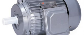
AC powered motor
The rotor rotates on two support bearings pressed onto its shaft. Cooling of an electric motor operating at high speeds occurs thanks to the impeller - a small fan consisting of many blades and located at one end of the rotor shaft. The ribbed structure of the aluminum housing also contributes to effective cooling of the operating unit.
The operating principle of such an engine is as follows:
- When current is connected to the unit, it alternately passes through one of three pairs of stator coils.
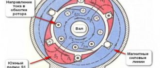
- When electric current flows through pairs of stator coils, they create a magnetic field, the lines of force of which intersect the rotor.
- Alternately powered pairs of coils create a moving magnetic field, which, according to the law of electromagnetic induction, provokes the appearance of an electric current in the stationary metal rods of the rotor.
- The induced current in the rotor results in a force that pushes it out of the stator's magnetic field. Since the frequency of current supply to the stator coils is on average about 30 pulses per second, the buoyant force that appears in the rotor leads to its rotation at high speed.
Important! Depending on the simultaneity of the rotation of the rotor and the magnetic field generating this movement, an alternating current electric motor can be synchronous (the rotor of the unit rotates synchronously with the magnetic field of the stator) and asynchronous (the rotation of the armature is not synchronized with the movement of the magnetic field of the stator). The first type is characterized by high power and reliability, while the second is characterized by a wide variety of designs and applications.
DC machines
The most common brushed DC motor is an electrical unit consisting of:
- Cast iron body with cooling fins and a special mounting box for connecting the unit windings;
- Shaft made of durable tool steel with two bearings;
- An armature consisting of a core (a set of plates made of special electrical steel), an armature winding (coils of copper wire placed in the grooves of the core);
- An inductor consisting of excitation poles with coils of copper wire wound on them;
- Collector - copper plates located on the shaft, to which the leads of the armature winding coils are connected;
- Spring-loaded graphite or metal-graphite brushes (brush group).
Such an engine is cooled, like its analogue operating on alternating current, by an impeller located on the shaft.
DC motor
Important! Unlike an AC electric motor, the rotor speed in such a power unit is controlled by a special unit, which, using a Hall sensor mounted on the shaft, determines the position of the rotor and its speed.
A similar unit works as follows:
- Voltage is applied to the field winding, thereby creating a constant magnetic field;
- Through the brushes and commutator, voltage is supplied to the coils of the armature core - the magnetic field that arises is repelled from the same one formed by the inductor, as a result of which the engine begins to rotate (“starts”);
- Subsequently, when rotating, the remaining coils of the armature winding are energized through the brushes, which leads to uniform rotation of the armature at a certain speed.
The rotation of such a unit is stopped by stopping the supply of voltage to the brush group.
In addition to the electric motors described above, machines operating on direct current also include a rotary starter - a device necessary for starting gasoline and diesel internal combustion automobile engines.
What it is
An induction motor is a device that is used to convert electrical energy into mechanical energy. Operates on AC power. The main difference from a synchronous machine is that this motor has a stator rotation speed higher than the rotor frequency. This electric motor is very popular due to its reliability and ease of use.
A three-phase and single-phase motor consists of a stator and a squirrel-cage rotor, this is clearly demonstrated in the drawing below. The stator consists of separate cylindrical sheets of steel and a rotor. The grooves contain a winding made from a regular power cable. The winding of each groove is at an angle of 120 degrees relative to the other; in the section it becomes clear that during operation the grooves become a star or a triangle.
Photo - asynchronous motor
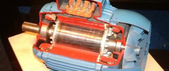
The rotor is the core that is located inside the stator. It is also assembled from individual steel sheets, which are joined together using molten aluminum alloy. Thanks to this, the entire structure forms studs (rods). They, in turn, are connected by short rings attached to the ends of the rods. Such a squirrel cage can also be connected with copper rings, but then the motor is used at lower voltages so as not to melt the metal.
Photo - rotor design
It should be noted that thanks to this design, servicing an engine with an asynchronous type of operation is simpler than a synchronous one. Due to the absence of brushes, the operation of the device is significantly extended.
The devices come in closed and open versions. The explosion-proof device is located in a special casing; it is protected from fire during unstable network operation. Also depending on the location of the rotor, devices are of the following type:
- Availability. Compared to synchronous machines, asynchronous machines cost much less. Moreover, they are very common. They can be found in specialized stores, markets, Internet portals;
- Reliability. In addition to the absence of brushes that fray, which significantly extends the life of use, the device is also susceptible to slight overloads. This is necessary if the engine is used in powerful industries where voltage surges are possible;
- Ease of use. Start-up is carried out in simple, intuitive steps. A simple circuit is used to switch on;
- High efficiency indicators, compared with synchronous machines.
Photo - engine types
At the same time, an asynchronous motor with a squirrel-cage rotor has disadvantages:
- High starting current at rated speed. During the first start-up, severe overloads of the electrical network are possible;
- Low level of protection. Despite the protected design of the windings, motors of this type are susceptible to breakdowns. In particular, the winding often burns out due to constant voltage drops;
- Slip coefficient too low.
Video: Three-phase asynchronous motors
Rotor types
Operating principle of the electric motor
Depending on the area of application and structure, rotors are of the following types:
- Phase - armatures of this type are a set of coils wound on a core, located relative to each other at an angle of 1200. The ends of the coil wires are led out to the collector plates and are powered using a brush assembly.
- A squirrel-cage rotor of this type consists of a solid cylinder with grooves into which rods made of electrolytic copper or aluminum are placed. The ends of such rods are connected to each other by a ring. There is no collector and brush assembly in units equipped with such an armature.
Motors with a phase armature type are large in size and weight, but at the same time have excellent starting and adjustment. Units with squirrel-cage rotors are smaller in size, less susceptible to breakdowns, and easier to operate.
Having understood what a rotor and stator are, you can gain not only useful theoretical knowledge, but also practical skills: knowing the design of units operating on direct and alternating current, if there is a malfunction, you can check the performance of their main components and determine whether the armature winding, stator, brush or commutator assembly is damaged.
Also, having answered the question “what is a rotor” and delved into the structure of this part, you can rewind the burnt windings yourself, which, in turn, is quite a popular and highly paid job.
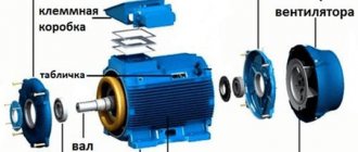
Electric motor components
The rotor shaft has a cylindrical shape and is made of steel. Metal rods that close on both sides give it its name - a squirrel-cage rotor. This design provides a high degree of protection, since there is no need for frequent maintenance of the device, there is no need to replace current supply brushes, etc.
If you look closely at the photo of the electric motor rotor, it resembles a squirrel cage, hence the name “squirrel cage.” The structure consists of assembled steel sheets of small thickness. A winding, which can be of several types, is placed in special grooves.
The answer to the question of what type of motor is a phase or squirrel-cage type is of decisive importance. The latest design innovations are more common. Copper rods that are thick are placed in the grooves without additional insulation. Copper rings allow the ends of the winding to be connected.
There are situations when the “squirrel cage” receives an alternative in the form of casting. This is the general design of the rotor of a squirrel-cage electric motor.
The main causes of failure of an asynchronous type motor include wear of the bearings in which the shaft rotates. Centering or balancing of the electric motor rotor is carried out using covers installed in the stator. The motors also have bearings to facilitate rotational movements.
In addition, the device involves the installation of an impeller, which ensures proper cooling of the engine. The stator has special fins that improve heat transfer from the heated device. This is how AC motors operate under normal thermal conditions.
Main differences
The presence of armature windings is one of the main differences between the two types of motors
Despite the external similarity, asynchronous motors and synchronous-type devices have several fundamental differences:
- the rotor of asynchronous motors does not require current supply, and the induction of the poles depends on the magnetic field of the stator;
- the rotor in a synchronous motor has an excitation winding under independent power conditions;
- the speed in an asynchronous motor under load lags behind the rotation of the magnetic field inside the stator in terms of slip;
- The revolutions in synchronous motors correspond to the frequency of “revolutions” of the magnetic field in the stator and are constant under different load conditions.
Stators in asynchronous and synchronous motors are characterized by the same design and create a rotating magnetic field.
Synchronous motors are capable of operating with the simultaneous combination of the functions of a motor and a generator.
Advantages of AC motor
The main feature of the characteristics of this engine and their most valuable manifestation is the fact that the load on the engine practically does not depend in any way on the shaft speed. Magnetic fields and electromotive force have been studied for two hundred years, and our asynchronous motor has become the best confirmation of this; it is one of the most effective methods of energy transformation.
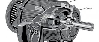
The operating principle of this motor is precisely based on the interaction of a moving magnetic field and a conductive element located inside this field. An engine, as has been known since school, consists of two basic units - a rotor and a stator. The stator just generates a rotating magnetic field. Structurally, the stator is a metal core; a winding of copper wire with thermovarnish insulation is wound around it.
Inside the stator, inside its magnetic field, a rotor was placed, which is a shaft with a core and a winding. The figure below shows a diagram of an asynchronous motor. From the diagram it is clear that the stator consists of stacked plates and several windings that are wound on a plate core. These windings can be connected in different ways, depending on the type of voltage. Each of their windings is shifted relative to each other by 120 degrees. And the rotor of such an engine can be of fundamentally two types.
Turbogenerator design
A turbogenerator is a synchronous generator working in tandem with a turbine. The main function is to convert the mechanical energy of rotation of a steam or gas turbine into electrical energy. Rotor speed 3000, 1500 rpm. Mechanical energy from the turbine is converted into electrical energy through the rotating magnetic field of the rotor in the stator. The rotor field, which is created by the direct voltage current flowing in the copper winding of the rotor, leads to the occurrence of three-phase alternating voltage and current in the stator windings. The stronger the rotor field, the greater the voltage and current on the stator, i.e. more current flowing in the rotor windings. The voltage and current in the rotor windings are created by a thyristor excitation system or exciter - a small generator on the shaft of a turbogenerator. Turbogenerators have a cylindrical rotor mounted on two plain bearings; in a simplified form, it resembles an enlarged generator of a passenger car. 2-pole (3000 rpm), 4-pole (1500 rpm as at the Balakovo NPP) are produced, therefore, they have high rotation speeds and problems associated with this. According to the methods of cooling the windings of a turbogenerator, they are distinguished: water-cooled (three waters), air-cooled and hydrogen-cooled (more often used at nuclear power plants).
Depending on the cooling system, turbogenerators are divided into several types: air-cooled, oil-cooled, hydrogen-cooled and water-cooled. There are also combined types, such as hydrogen-water-cooled generators. There are also special turbogenerators, for example, locomotive ones, which serve to power the lighting circuits and radio station of a steam locomotive. In aviation, turbogenerators serve as additional onboard sources of electricity. For example, the TG-60 turbogenerator operates on compressed air taken from the aircraft engine compressor, providing drive for a three-phase alternating current generator of 208 volts, 400 hertz, with a rated power of 60 kVA*A.
Turbogenerator design
The generator consists of two key components - the stator and the rotor. But each of them contains a large number of systems and elements. The rotor is a rotating component of the generator and is subject to dynamic mechanical loads, as well as electromagnetic and thermal loads. The stator is a stationary component of a turbogenerator, but it is also subject to significant dynamic loads - vibration and torsion, as well as electromagnetic, thermal and high-voltage loads. The initial (exciting) direct current of the generator rotor is supplied to it from the generator exciter. Typically, the exciter is coaxially connected by an elastic coupling to the generator shaft and is a continuation of the turbine-generator-exciter system. Although large power plants also provide backup excitation of the generator rotor. Such excitation occurs from a separate pathogen. Such direct current exciters are driven by their own three-phase alternating current electric motor and are included as a reserve in the circuit of several turbine units at once. From the exciter, direct current is supplied to the generator rotor by means of a sliding contact through brushes and slip rings. Modern turbogenerators use thyristor self-excitation systems.
Tags: asynchronous, sconce, type, excitation, generator, engine, house, how, capacitor, design, magnet, magnetic, installation, power, load, voltage, nominal, steam, constant, principle, wire, start, work , rheostat, switch, row, network, system, means, term, diagram, type, current, transformer, triangle, three-phase, , photo, shield, electric motor, effect