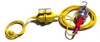
Step-down voltage transformers are required, and sometimes irreplaceable, in conditions where there is a risk of electric shocks due to an unfavorable environment, for example, in damp rooms. In such situations, models of the indicated devices are used, including 36 Volt ones. This way, if there is contact with the electrical network, the shock will be minor, and it is less likely to damage other devices. There are ready-made modules - YTP (box with a step-down transformer, details later in the article) - for which you do not need to deal with contacts. But the 220/36 V step-down transformer (VT) itself is a device that cannot be immediately plugged into an outlet without preparation; you need to know how to connect it to the wiring. Let's consider the rules, connection options, preparatory steps, and warnings.
What is a 220/36 V step-down transformer
Why do you need a step-down transformer:
- premises where, according to safety rules, high currents present in a regular 220 Volt network (alternating voltage) are prohibited. This is, for example, lighting in saunas, baths, bathrooms, garage pits, where switching to low-voltage power is required;
- for conditions in which reduced voltage is required due to the characteristics of the powered devices. Often 36 Volt soldering irons are connected through the device. The electric shock will be insignificant and will not cause harm to a person;
- For safety, the voltage is reduced during temporary repair work.
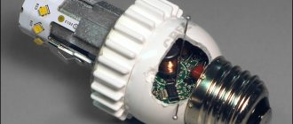
The devices in question, if it is not a module (YTP), cannot be immediately taken and connected to an outlet, since they do not have a protective casing, their elements are visible - primary and secondary windings, magnetic circuit, contacts. Such converters are connected by wires, so the user must become familiar with which turns to connect the 220 network to, which contacts are used to output voltage already converted to 36 V to consumers.
Step-down models are ordinary transformers operating according to standard principles, only these devices convert alternating voltage (and this is what a regular 220 V network has) into a smaller one. If, for safety reasons (humidity, repairs), it is necessary to reduce the voltage of the 220 V line to 24, 45 and so on, and in our case to 36 V, then separate units are installed, the input of which is supplied with 220 V, and at the output we get the indicated or other set value.
Design and operating principle
Which transformer is called a step-down transformer? The basis of the step-down transformer device consists of a ferromagnetic core with two windings located on it. They are wound with copper wire and separated from each other as primary and secondary. The primary winding is connected to the mains voltage, and consumers designed for low current are connected to the outputs of the secondary winding.
The connection between the windings is carried out through an alternating magnetic flux induced in the core, since there is no direct electrical connection. The number of turns in the primary winding is much greater than in the secondary, which provides the necessary voltage reduction. For most models, all components are placed in a common housing, but there are also open-type designs with a limited scope.
In the classic version, a step-down transformer uses electromagnetic induction. The voltage applied to the primary winding gives rise to a magnetic field that crosses the turns in the secondary winding. This leads to the formation of an EMF, under the influence of which a reduced voltage occurs. The difference between the input and output voltage is determined by the number of turns in each winding. During operation, a certain amount of electricity is lost, within 3% of the total power. This is the general operating principle of such equipment.
The exact parameters of the device are determined by the calculated data of its structural elements. The emergence of electromotive force is possible only under the influence of alternating current, which is why many household devices are designed for precisely this current. A step-down transformer very often functions in conjunction with power supplies, stabilizers and other similar devices.
Modern models are equipped with several leads from the secondary winding, designed for different types of connections. As a result, each such device acquires multifunctionality and versatility and is called a step-down device. When the connection diagram changes, it becomes step-up.
Transformer types
There are different types of step-down TN. The usual and most common is single-phase for a 220 V network. There are also two- and three-phase for 380 V. The most standard composition: two windings and a laminated core made of electrical steel.
Certain types of VTs are equipped with 1 winding - these are autotransformers, they can also step down / step up. In this case, there are at least 3 conclusions. A 220 V connection is made to one pair of contacts, and the output value is taken from one of the input pairs of terminals and from the other that remains free. But autotransformers cannot be used in wet rooms, since the coils in them are connected, that is, the consumer is also connected to 220 V.
Popular connection schemes
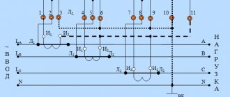
If CTs are used to connect voltmeters, ammeters and other highly sensitive instruments through them that measure low current, the current transformers are connected according to the following scheme:
The primary winding L1-L2 is connected to the linear wire, and the secondary winding of the CT I1-I2 is connected to the current winding of the measuring device. Terminals L1, I1 are connected by a jumper and connected to the phase wire. The third clamp is connected to the neutral wire.
For a three-phase power supply, three single-phase transformers are most often used, which are connected according to the following diagram:
If you need to connect a step-down device, you should follow the diagram:
Most often it is used to create lighting systems. The small size of CTs makes it possible to mount them directly in the ceiling frame. The transformer is located between the switch and the lamps. The lamps are connected in parallel.
How to choose
The VT we need on the marking should have a designation for input contacts of 220 V, at the output - twelve volts or another voltage according to our requests. Other models may be designed for 380 V, for 2-, 3-phase networks.
When selecting, you need to add up the power of all consumers on the serviced line and compare it with the figure (kVA) for which the transformer is designed, adding 20% of the reserve.
Separation of voltage-reducing devices by type
Transformers are divided according to design features into 2 types:
- Toroidal, or electromagnetic, is an outdated option that has large dimensions and a lower efficiency factor (efficiency). This type is practically no longer used for domestic needs;
- electronic (pulse) devices are compact, lightweight, with a high percentage of efficiency, tending to 100%.
Despite the fact that the former are gradually being replaced by the latter in all areas, it would be a mistake not to consider them.
Toroidal transformer 220 to 12 volts: device, circuit
A fairly simple device consisting of two coils with different numbers of turns mounted on one steel core. The change in output voltage depends on the difference in turns. According to the laws of physics, any conductor through which electric current flows creates an electromagnetic field around itself, which intensifies when the wire is wound into a coil. Thus, the current flowing through the primary coil (to which voltage is applied) creates a strong electromagnetic field, which is transmitted through the steel core to the secondary coil, from which the voltage is removed.
Chinese converters can be quite high qualityImportant! Without a steel core, such a device will not work, even if the secondary coil is wound directly onto the primary one. Moreover, such an attempt will lead to burnout of the primary coil wire
Below is a diagram of a simple toroidal transformer.
Electronic device for reducing household voltage
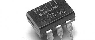
The circuit of the 220 to 12 volt electronic transformer is more complex, however, its operating principle is the same. A small ferrite ring with windings acts as a steel core with a large number of turns. The main work is performed by thyristors (dinistors), various limiting resistors and transistors. A detailed diagram can be found below.
Pulse step-down devices have a number of advantages over electromagnetic ones:
- small dimensions and weight;
- high efficiency;
- minimal heating, which is completely unnoticeable with proper ventilation;
- long service life.
Important! Despite all the advantages of pulse generators, they have one drawback - such a transformer cannot be connected to the network without a load. If turned on in this way, the device quickly burns out.
Connection features
Let's look at the basics of how to calculate and connect a step-down transformer 220 36. It is important to connect to the coils of the device in strict accordance with their purpose, taking into account the needs of a specific situation. Depending on where the load is connected and 220 V, the device will be either a step-down or step-up device. And incorrect connection of the winding contacts will lead to rapid failure of the voltage transformer (overheating, short circuit).
The VT is connected in parallel with the load, its purpose is to transform the input voltage with a certain ratio, which, if simplified, is equal to the turns ratio. When their number in a primary (network) is less than in a secondary, then the output value decreases. The step-up voltage transformer has the opposite - there are more turns of the secondary (load coil). It should be noted that when the load increases, the coefficient. the ratio decreases, which is also affected by the cross-section of the winding wires.
For complex products, the number of coils exceeds 2, each with its own coefficient. transformations, some of them decrease, some increase. Any transformer can operate in reverse mode: when an alternating voltage is applied to the load winding, we obtain it at the output of the primary with the same conversion coefficient.
How does a transformer work?
Already today, a huge number of current converters have been created; there are low-voltage and high-voltage models. The principle of operation of the transformer is quite simple - a step-down transformer is responsible for reducing the incoming current, while a step-up transformer, on the contrary, increases the voltage to a higher value.
For domestic purposes, this is a very important device; it ensures stable operation and complete safety of household electrical appliances.
Let's give a simple example. In many homes, a current of 385 Volts is supplied from the network, and standard household appliances operate only on 220V. In this case, you cannot do without a step-down transformer, so you will have to buy a single-phase or three-phase converter.
Converter 380 Volt - industrial type, three-phase. Converter 220 Volt - standard household, single-phase.
When using a standard household transformer, its task will be simpler, because depending on the model, it changes the current to 12, 36, 42 Volts (depending on the requirements of household appliances).
The principle of operation of the design is simple - a larger value of current passes through one winding, after which a smaller current is issued from the second winding. This became possible due to the fact that there are more turns on one winding, and fewer turns on the second. Speaking in scientific language, this process is called electromagnetic induction.
How to connect a step-down transformer
Preparatory stages:
- Make sure that the device used is a voltage transformer (there are also current ones). To connect the load, you need to choose a coil with the highest number of turns and resistance.
- Anode-filament versions of devices have windings of all types. You can recognize the primary by looking at its conclusions - they are usually at a distance from the rest. Sometimes such turns are isolated in another segment of the frame, then it is even easier to recognize it. There are also many thematic forums on the Internet, so it won’t be difficult to clarify the device parameters there and where the output is.
- Be sure to check the voltage value and the frequency of the VT - it should be 220 V and 50 Hz.
- Sometimes the network winding has 3 terminals, one of them is for a 110 or 127 V network. Our goal is to combine them so that the resistance is maximum, and it is to them that 220 V must be supplied.
- If there are not 3, but 4 inputs, then this is a model with 2 coils, which are connected by a jumper from the wiring in series, in phase. First, they do it, then the windings are connected to a voltmeter with a limit of 500 V. Next, several Volts are given to one of the load windings (you can use a battery). Do not touch the terminals of the network turns while doing this.
- Record the results of the tester, turn it off, swap the leads of any of the first coil, and repeat the process.
- Choose the option with the highest value.
If there is only one winding, it is advisable to connect it to the network through a fuse. The current rating is selected for the transformer - no more than 0.05 A per 10 W.
Connection procedure
The activation itself is simple. It is enough to remember the main rules:
- A load is connected to the contacts of the secondary coil, then 220 V is supplied to the primary. For this purpose, the device can be connected directly to the wiring (twisted, terminals), including directly in the panel, or its terminals can be equipped with a cord with a plug to a 220 V socket and an external socket for connected devices.
- The load goes to the winding with high resistance.
The main thing in connection is not to confuse the windings and terminals, take into account the operating principle of a step-down transformer 12, 24, 36 V: the load goes to the secondary and if it has several contacts, then at the output you can get a different voltage, for example, not 36, but 24 V. Therefore, a check with a voltmeter or multimeter is required, as described in the previous section.
A clear example with illustrations
Diagram of a conventional transformer:
The input is the primary, 220 V is supplied there. As can be seen in the diagram, some VTs have outputs for 110 V. 36 V or another reduced voltage is removed from the output.
Consumers powered by direct current must have a rectifier, a diode bridge, etc. - this will already be a power supply; this is not necessary for incandescent lamps.
The calculation must take into account that some transformers have two separate output windings that need to be connected by an external wire.
In our case, the model is normal, in the image the VT is located according to the diagram: the large coil is the input (there are two contacts for 220 V), the smaller one is the output.
If you measure with a tester (mode at 2000 Ohm), then the resistance is greater on the primary than on the secondary, thus determining which turns are which.
There are transformers with two identical windings - one has 110 V and the other also 110 V. To get 220 V, they must be connected correctly, otherwise a short circuit will result. Connect the output as shown in the image: bottom contact to bottom. Similarly, we connect two wires from the 220 V network and measure the resistance (second photo).
The secondary is wound in this case from above (that is, there are two coils, but each includes both a mains and a load). In it, you can connect the terminals of two windings as you like, but if you do this out of order, the current strength will increase by 2 times. If we connect it in series (the position of the fingers in the photo), then, for example, the calculation will be as follows: 18 V + 18 V = 36 V, which is what we need. Such converters are convenient in certain conditions: you can either increase the current by 2 times, or the voltage (already a reduced value at the output).
There are also transformers with multiple contacts for input (primary, first image) and output (second photo), from which you can remove different voltages depending on the order in which their contacts are connected. The principle of the combination is similar to that described above, but we will not indicate it specifically here, since there are many models of such products. The easiest way for the user is to refer to the product data sheet or special forums. The 1st photo shows resistance measurements on the primary, but you need to connect the load to the secondary (2nd and 3rd photos), and it will have a higher value.
Pros and cons of transformers
This technique has its advantages and disadvantages. When choosing certain models, you need to take into account all the nuances. Let's start with the pros:
- Human safety at home and in industrial environments is guaranteed by this mechanism, which reduces the level of electric current intensity to 12 V, thereby guaranteeing the preservation of life and health.
- The input voltage does not matter too much since the output current is stable.
- Compact and miniature box.
- Easy to move and install.
- Low heating of the case.
- Accurate voltage regulation.
- Not too long a service time.
- High price.
- Insufficient power.
Ready-made solutions - nuclear fuel technology boxes
YaTP is a step-down transformer immediately ready for connection, a module. No need to deal with pins, inputs, windings. The product has appropriately marked sockets for the required load, 36V or otherwise. It is enough to plug its cable into a 220 V network and connect it to the socket on the consumer’s body.
Nuclear fuel transformers can produce any low voltage - 24, 36, 42 V. They are often used for temporary repair work. There are models that allow you to adjust the output voltage.
Transformer characteristics
The design of the box with the transformer can be very diverse. The main element of the mechanism is a ferromagnetic core, the windings of which are framed by a special copper conductor. The primary part of the winding controls the voltage in the network, while the secondary is responsible for removing the reduced voltage.
The core emits alternating current, which creates a coupling between the two existing windings. The windings are not connected to each other by electric current. By the way, the ability to reduce tension arises due to the difference in the number of curls between these components.
Most often, these elements are protected by a special case, however, the structural features and varieties allow for various variations.
How to assemble a step-down transformer yourself
The first stage of assembly for the HP will be calculation. Then let's look at the process itself.
Calculus
We set the initial data for the 220/12 V converter:
- input/output - 220/12 V;
- cross area section heart S = 6 sq. cm.
Calculation of the number of coil turns:
Primary N1 = 60×220/6 = 2200 turns
Secondary N2 = 60×12/6 = 120 turns.
Assembly
Preparation of materials:
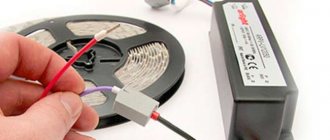
- copper wire in silk/paper insulation: for primary - cross-section 0.3 mm², for secondary - 1 mm². For the last digit, the connected load in the circuit must have up to 10 A. There is also a special winding wire (enamel wire) on sale; it can also be removed from other transformers. It is also permissible to use a regular copper wire in plastic insulation;
- 5–6 pieces, or more as needed, of tin cans: their tin can be used to create a core;
- cardboard - thick, hard;
- varnished fabric (tape insulation);
- waxed paper.
Stages
The procedure for making a transformer with your own hands:
- 80 strips of 30x2 cm are cut out of the cans. The tin is annealed: it is heated in a furnace and left to cool there. The point is precisely gradual, as slow cooling as possible: the steel softens and loses its elasticity;
- the plates are cleaned, varnished, each is covered on one side with thin paper - tissue paper, with paraffin, tracing paper;
- A frame for the windings is made from cardboard. It consists of a barrel and cheeks, wrapped in several layers of waxed paper, which can be replaced with drawing tracing paper;
- The wire is wound turn by turn, and wax-treated insulation is laid every 2–3 layers;
- after winding is completed, the primary fixes the ends of the core on the cheeks, the coil is wrapped in 5 layers of paper;
- the winding on the secondary should coincide in direction with that on the primary;
- having fixed the leads of the load coils on the second frame cheek, it is also wrapped in paper;
- the plates are placed halfway into the coil, then they are wrapped around the frame (the gap between these elements is mandatory) so that the ends meet under it;
- The VT is secured, for example, with staples on a piece of wooden board. The last stage is when the ends are brought out onto the base and equipped with contacts.
You can make a calculation by analogy as described and create a VT simultaneously for twelve and twenty-four volts, which is required when using different lamps. They wind 240 turns, but from the 120th turn the contact is removed in the form of a loop.
Features of transformers for halogen lamps
To properly control the operation of a halogen lighting device, be sure to use a transformer that reduces the output voltage to 12 volts. Thanks to this, the lamps are protected from overvoltage and power surges.
Such converters normalize incoming electricity and output the required voltage level from 6 to 24 volts, depending on the halogen lamp used. Today, there are two main types of step-down transformers, depending on the design of the device:
- toroidal winding converters;
- electronic or pulse step-down transformers.
Standard winding transformers are considered the most affordable and easiest to operate, and also have good power performance. It is easy to connect a halogen light source to such a device.
The operating principle of such a converter is based on the electromagnetic interconnection of the device coils. But due to the use of the latter, such a transformer has serious disadvantages - heavy weight, reaching several kilograms, and dimensions that take up a lot of space. It is for this reason that such voltage-reducing devices are not widely used in everyday life.
Plus, the electromagnetic converting device gets very hot during operation, which can negatively affect halogen lamps. In addition, overheating of toroidal winding transformers can lead to voltage surges in the house, thereby adversely affecting other household devices.
In turn, low-voltage pulse converters, which are also called electronic transformers, have received the widest possible range of applications both in everyday life and in production. This popularity is primarily due to the low weight and dimensions of the device. In addition, such a device qualitatively reduces the voltage without heating up during operation. The only disadvantage of such a transformer for 12-volt halogen lamps is the fairly high cost of the device.
Recently, pulsed step-down transformers have appeared on the electronics market, which, even at the production stage, are equipped with built-in protection against short circuits and overvoltage, which significantly extends the service life of both the converter and light sources.
Such electronic converters are often used for mounting halogen light sources in the furniture industry or suspended ceilings. According to the principle of operation, such a transformer will differ from its winding analogue in that energy conversion is achieved through semiconductor devices and electronic spare parts.
Buy a step-down transformer from 220 to 12 volts
Today, devices of various designs and designs are available for sale. You can order or buy both in retail stores and online stores. The latter, by the way, have more favorable prices.
Below we invite you to familiarize yourself with and compare several options:
| Model | NEO-1.0 | OSOV-0.25 | TP1-0.25 | OSVM-0.25 | YaTP-0.25 |
| Approximate price, rub | from 6500 | from 2200 | from 5300 | from 5300 | from 1500 |
| Appearance | |||||
| Power, kVA | 1 | 0.25 | 0.25 | 0.25 | 0.25 |
| Primary voltage, V | 220 | 220 | 220 | 220 | 220 |
| Secondary voltage, V | 12, 24, 36, 42 | 12, 24, 36, 42, 110, 127 | 12, 24, 36, 42, 110 | 12, 24, 36, 42, 110, 127 | 12 |
| Degree of protection | IP20 | IP65 | IP20 | IP55 | IP31 |
| Climatic performance | U2 | U5 | U2 | OM5 | UHL 4 |
| Dimensions, mm | L - 275 W - 155 H - 270 | L - 200 W - 200 H - 225 | L - 320 W - 160 H - 302 | L - 200 W - 200 H - 225 | L - 210 W - 145 H - 145 |
| Weight, kg | 16 | 5.9 | 13 | 5.9 | 6.5 |
| OSZ – single-phase, dry, protected design | |||||
| OSOV – single-phase, dry, for local lighting, waterproof design | |||||
| TP – dry single-phase | |||||
| OSVM – single-phase, dry, waterproof, marine | |||||
| YTP - box with NEOs |
As you can see, a distinctive feature of all transformers is their design. For outdoor installation, we recommend choosing the OSOV or OSVM , as they have a waterproof design.
How to connect correctly
To ensure that the capacitors work correctly when independently assembling a 12V transformer power supply, the device is equipped with a resistor at the output with a resistance of 3 to 5 MΩ.
Voltage or current stabilizer
A standard type power supply is assembled using an electrolytic capacitor with a capacity of no more than 10,000 μF, a full-wave bridge rectifier made of diodes with a reverse voltage of 50 volts and a forward current of 3A, as well as a 0.5A fuse. A 7912 or 7812 capacitor is used as an integrated voltage stabilizer for 12V.
Integrated voltage stabilizer
Without the use of a voltage stabilizer, the power supply will not be able to function properly. The capacitors of the LM 78xx and LM 79xx series are used as these components. Zener diodes are selected according to the appropriate current and voltage parameters; there are a large number of them on the market, but the most advanced element is considered to be the KR142EN12 type.
Series LM 78xx
These voltage regulators have an output current of up to 1A, and an output voltage of: 5, 6, 8, 9, 12, 15, 18, 24. In addition, these capacitors have thermal overload protection and short circuit protection.
Series LM 79xx
These voltage regulators have similar values to the 78xx series. They also feature thermal protection against large overloads and short circuit protection.
Types of transformers
At the moment you can find a huge number of step-down transformers. The main types include:
- Dry
- Oily
Dry models are used in everyday use to distribute incoming energy to the terminals of halogen lamps. Their advantage is that they are small in size and have a high protection class. Such transformers are often used in chemical plants or oil refineries. The scheme of their work is no different from the standard one.
They are also used for household and industrial circuits, to control the operation of halogen lamps and other devices.