Low voltage sources can be batteries, rectifiers if direct current is required, single-phase low-power transformers (up to 1 kVA), portable or stationary.
Resistors, chokes, etc. It is unacceptable to use it to reduce the voltage at an electrical receiver.
A portable transformer must have a flexible wire for connection to the network, enclosed in a protective sheath made of rubber or polyvinyl chloride, and a plug for connection to a plug socket installed on the panel in the switchgear or in areas of use in the workshop.
All grounded parts, including secondary windings and low voltage circuits, receive the same voltage in relation to the ground. This voltage (especially in 380/220 V networks) can significantly exceed the voltage of 42, 36 or 12 V. Meanwhile, it is believed that touching live parts at these voltages is not dangerous.
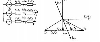
Rice. 2. Turning on the separating transformer (a) Double circuit in the network fed through the separating transformer (b).
If this short circuit in one phase is not eliminated and insulation damage occurs on another phase of the secondary circuit (point B), then the fuse can only blow if there is a metal connection between points A and B; this will not happen in most cases. A voltage will appear on the body of the electrical receiver in relation to the ground, which will depend on the ratio of the resistance at point B and the human body (including the resistance of the floor and shoes). This voltage can be dangerous if a person is standing on the ground or on a conductive floor and shoes have low resistance.
To reduce the likelihood of double short circuits, no extensive network should be connected to the separating transformers on the secondary side. So, with two or more electrical receivers, a short circuit in them with connection to the ground in two different phases is possible. Such double circuits can already lead to defeats. Therefore, each power receiver must have its own separating transformer.
The use of isolating transformers provides a significant improvement in safety conditions compared to power supply directly from the network or through step-down transformers with grounding of the secondary windings.
Source
This need arises when using portable power receivers, as well as for lighting particularly dangerous rooms, in outdoor electrical installations.
Batteries and rectifiers, single-phase transformers, whose power is low, can serve as low voltage sources. Resistors and chokes should not be used to reduce voltage.
Low-power step-down transformers are produced both for installation on machines and portable. The flexible wire for connecting to the network must have a portable transformer. The wire must be enclosed in a sheath made of rubber or polyvinyl chloride, and also have a plug that serves to connect to a reliable plug socket. The socket can be installed on the panel in the switchgear, or in the workshop in the application areas.
For step-down transformers, the secondary windings must be grounded. This is due to the fact that there is a danger of damage to the transformer itself during the transition of higher voltage to lower voltage.
This scheme has a drawback. Indeed, in the event of a short circuit to the ground or to the body, the conductors (grounding) are under some voltage until the damaged area is disconnected. All grounded parts are under this voltage. Many people believe that this situation is not dangerous. All this can be avoided by using isolation transformers.
Increased demands are placed on them. There must be no damage to the insulation inside the transformer itself when voltage transfers from the primary side to the required secondary side. The use of isolation transformers is associated with simultaneous voltage reduction, as well as voltage separation.
The use of isolating transformers leads to improved safety conditions. They are much more efficient than when powered directly from the network, as well as using step-down transformers, where the secondary windings are grounded.
Here it is constantly necessary to monitor the insulation condition of transformers, secondary network wires and power receivers. This control prevents single-phase faults.
Source
Reduced (low voltage)
Low voltage sources (12, 24, 36 and 42V) can be batteries, step-down transformers, frequency converters.
At the same time, the use of autotransformers and rheostats to reduce voltage is prohibited due to the connection of low- and high-voltage networks.
To reduce the danger of using step-down transformers, the secondary winding and the transformer housing are grounded or grounded.
Protective grounding, grounding
Safe work with electrical installations is ensured by grounding, grounding (in networks up to 1000V) and protective deflection.
According to GOST 12.1. 013-80 and GOST 12.1.030-80 “Electrical safety. Protective grounding, grounding", GOST 12.1.019-79 "Electrical safety. General requirements and nomenclature of types of protection,” grounding or zeroing should be performed:
- at a rated voltage of 380V and above alternating current, 440V and above direct current in electrical installation networks in any premises (including premises without increased danger);
- at a rated voltage of 36V and higher (according to GOST 12.1.013-80), 42V and higher (according to GOST 12.1.030-81) alternating current and 110V and higher direct current of electrical installations in high-risk premises and especially hazardous premises, in outdoor electrical installations;
- at any rated voltage of alternating and direct current electrical installations in all explosive conditions.
Parts of electrical installations that are subject to grounding or grounding:
— metal housings of electrical machines, transformers, apparatus, lamps, mobile electrical installations, portable electrical installations;
— frames, control panels, control rooms and cabinets, as well as removable or opening parts, if electrical equipment with a voltage higher than 42V AC or a voltage higher than 110V DC is installed on them;
— drives of electrical devices;
— secondary windings of instrument transformers;
-metal switchgear, metal small structures, metal couplings, metal sheaths and armor of control and power cables, metal sheaths of wires, electrical wiring pipes, etc.;
— reinforced concrete power transmission line supports.
According to its functional purpose, grounding is divided into three types - working, protective, lightning protection grounding.
Working grounding includes grounding of the neutrals of power transformers and generators, dead or through an arc suppression reactor.
Protective grounding is performed to ensure the safety, first of all, of people.
Lightning protection grounding serves to drain lightning current into the ground from protective arresters and lightning rods (rod or cable).
Protective grounding must fulfill its purpose throughout the year, while grounding and lightning protection - only during thunderstorms.
Purpose of protective grounding
. Protective grounding is intended to eliminate the risk of electric shock to people when they come into contact with metal parts of electrical equipment that are energized. The operating principle of protective grounding is to reduce touch and step voltages caused by a short circuit to the body of electrical equipment to a safe level. This is achieved by reducing the potential of the grounded equipment due to the low resistance of the ground electrode, as well as by equalizing the potentials of the base on which the person is located and the grounded equipment by raising the potential of the base to the level of the potential of the grounded equipment.
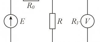
Protective grounding is a parallel connection to the electrical circuit of a grounding conductor with a significantly lower resistance Rз
In networks with voltages up to 1000V, the resistance of the grounding device should be no more than 4 ohms, for voltages above 1000V - no more than 0.5 ohms.
With this inclusion in the electrical circuit, the current passing through the person will be equal to:
(3.4.21)
where, Rr
– human body resistance, Ohm
Rtotal –
total resistance of grounding conductors, Ohm.
Fig. 3.4.6 Protective grounding: a – grounding diagram of the electrical equipment housing; b-equivalent electrical circuit
(3.4.22) (3.4.23)
After substituting the values of Rtot
and
Itot
into formula / 3.4.21/ we obtain
(3.4.24)
Determine the magnitude of the damaging current when a person is single-phase connected to a three-phase network with an isolated neutral.
Let's assume that the resistance of the floor and shoes: Rп = Rоb = 0 Ru = 3000 Ohm
In the absence of grounding, the damage current:
A
If there is a protective ground:
A
As you can see, the damage current in the presence of a grounding device is significantly less than the holding one.
Protective grounding is used in electrical installations with voltages up to 1000V AC with an isolated neutral or with an isolated output of a single-phase current source, as well as electrical installations with voltages up to 1000V in DC networks with an isolated midpoint.
Grounding of installations consists of connecting their metal parts (normally not energized) to the ground with a ground electrode having low resistance to current flow.
The grounding device consists of grounding conductors, grounding bars and wires connecting the housings of electrical installations with grounding conductors.
Depending on the location of the grounding conductors relative to the grounded equipment, grounding devices are divided into remote and loop (Figure 3.4.7). External grounding switches
the grounding device is placed at some distance from the grounded equipment.
A loop grounding
device provides a higher degree of protection, since grounding conductors are located along the contour of all grounded equipment.
Fig. 3.4.7 Remote (a) and loop (b) grounding:
1-electrodes (grounding electrodes); 2 currents (buses); 3-electrical installations
In practice, grounding is carried out in the following order:
— a grounding device (artificial or natural) is selected;
— the grounding device is calculated;
-separate electrodes (grounding electrodes) are combined into one common grounding device;
— electrical installation housings are connected to a grounding device;
- documentation is drawn up for acceptance of the grounding device into operation.
When choosing a grounding device, natural grounding conductors are often used, which are pipelines laid in the ground and having good contact with the ground, steel pipes of electrical wires. During the construction of industrial buildings, metal building frames can be used as natural grounding conductors.
Pipelines for flammable liquids and explosive gases must not be used as grounding conductors. Metal and reinforced concrete structures, when used as grounding devices, must form a continuous electrical circuit through the metal (in reinforced concrete structures, embedded parts must be provided for connecting electrical and technological equipment).
When using reinforced concrete foundations as grounding conductors, the current spreading resistance of the grounding device is determined by the formula
(3.4.25.)
Source
The concepts “actual voltage level” and “actual voltage” are different concepts
To determine the tariff for electricity transmission, it is important to establish at what “actual voltage level” the electricity consumer is connected. Not at what “ actual voltage ”, but at what “ actual voltage LEVEL ”. It's not the same thing.
These concepts become almost identical in a situation where the consumer’s balance sheet boundary is NOT at the POWER SOURCE.
In this case, the “ actual voltage ” of the consumer’s EPU at the point of connection to the TSO power grid facilities is taken as the “ related to the corresponding “ voltage level
That is, the “actual voltage” of the EPU coincides with the “voltage” that refers to one or another “voltage level”. “ Actual voltage ” of the consumer’s EPU at the point of connection to the electric grid facilities TSO PREDETERMINES the “actual voltage LEVEL” used to select the tariff for electricity transmission.
For example, if you have the “actual voltage” of the EPU at the point of connection to the TSO power grid facilities is 6 kV, and this connection point is NOT at the power source, then the voltage related to the corresponding “ voltage level ” will also be 6 kV. Therefore, the “voltage level” will be “average second” (CH2), since the EPU voltage completely coincides with the voltage related to the second “voltage level” (CH2). Hence, your “actual voltage level” at which your EPUs are connected to the TSO power grid facilities will be completely determined by the above-mentioned coincidence of “voltages”: the EPU voltage and the voltage related to the corresponding “ voltage level ”.
Next, based on the “actual voltage level”, according to the TSO tariff menu, we determine the value of the tariff for electricity transmission corresponding to the voltage level - the average second voltage (CH2).
The situation is completely different when the consumer’s balance sheet boundary is at the POWER SOURCE.
How to eliminate voltage sags?
To fix the voltage sag problem, you first need to determine its source. It is necessary to study the condition of the internal electrical system. To do this, you should seek the help of specialists who will correctly and comprehensively diagnose it. If the wiring is in order, then the reason will be related to the work of the energy supply organization. And you will either have to deal with this company, demanding to ensure the supply of high-quality voltage in accordance with GOST, or install a voltage stabilizer.
The stabilizer is the most effective means of protecting responsible consumers from surges and sags in mains voltage. The device is capable of adjusting the voltage supplied from the external network, bringing it to the nominal value. If the signal goes beyond the operating range of the device, then it goes into emergency mode, de-energizing the circuit and load.
Note!
Some users believe that a voltage control relay (VCR) is comparable in functionality to a stabilizer. However, the RKN is only capable of disconnecting the protected section of the network when the voltage leaves the range of its operation set by the user. This device will not be able to correct low voltage.
Note!
If the electrical network experiences voltage drops below 90 V or its complete loss for more than 0.2 s, then instead of a stabilizer it is more advisable to install an online topology uninterruptible power supply, which will not only correct the low voltage, but also provide the load with autonomous operation during the period of loss of the input signal .
Types of stabilizers and their capabilities for correcting voltage sags
Today, there are several types of voltage stabilizers on the electrical market, among which relay, electromechanical, electronic and inverter models stand out. Each of them has certain technical capabilities for correcting low input voltage.
Let's look at the technical characteristics of each of them in more detail:
| Stabilizer type | Technical capabilities (characteristics of some stabilizers may differ from those shown in the table) |
| Relay | · maximum input voltage range – 120-276 V (for some models 140-260 V); · reaction to a sharp decrease in voltage – from 10 to 20 ms; · Voltage correction accuracy – 5-10%. |
| Electromechanical | · maximum input voltage range – 130-276 V (for some models 150-250 V); · reaction to a sharp decrease in voltage – more than 100 ms; · Voltage correction accuracy – 2-5%. |
| Electronic (triac and thyristor) | · maximum input voltage range – 120-280 V; · reaction to a sharp decrease in voltage – from 10 to 20 ms; · voltage correction accuracy – 4-10%. |
| Inverter | · maximum input voltage range – 90-310 V; · response to a sharp decrease in voltage – 0 ms; · Voltage correction accuracy – up to 2%. |
Comparing the technical characteristics of different types of stabilizers, we can conclude that among the above devices, inverter models have the widest range of input voltage, have a higher accuracy of its correction and are able to instantly respond to sudden drops in the input signal.
These features make it possible to use inverter models in case of very significant network drawdowns, which are often found in holiday villages and villages, to protect the most demanding power consumers, for example, the electronics of gas boilers and circulation pumps.
Advantages and features of inverter stabilizers "Stil"
One of the most famous manufacturers of inverter voltage stabilizers is Shtil Group of Companies, which today produces more than 50 models of these devices on the Russian market, including:
- single-phase devices of wall and floor/rack design with output power from 0.3 to 18 kW;
- three-phase floor/rack mounted devices with output power from 5.4 to 16 kW;
- models of a unique 3-in-1 configuration of floor-standing/rack-mount design with output power from 5.4 to 16 kW, designed to protect single-phase loads in a 380/400 V network.
Shtil inverter devices operate on the basis of transformerless double conversion technology, due to which the input voltage is first transformed into direct voltage, and then, using an inverter, again converted to alternating voltage. They have the best technical characteristics in the category of inverter devices: they instantly respond to any voltage sags, adjust the input signal with high accuracy (±2%) in a very wide range (90-310 V), guaranteed to provide the load with an ideal sinusoidal voltage. In addition, Shtil devices protect responsible consumers from operational failures caused by short-term power outages (up to 0.2 s).
Each model of Shtil stabilizers is equipped with a full set of electronic protections: against network accidents, short circuits, surges, high-frequency interference, output overload, internal overheating and failures during operation.
The capabilities of Shtil inverter stabilizers for correcting low mains voltage are shown in the table below:
| Characteristics | Indicators |
| Minimum voltage value for correction | 90 V (copes with the most significant network sags) |
| Protection against voltage less than 90 V or its complete loss | yes (up to 0.2 s) |
| Response speed during voltage sags and surges | 0 ms (instantaneous) |
| Maximum deviation of output voltage value | no more than ±2% of the nominal value (acceptable for the most electrically sensitive consumers) |
| Output voltage form | pure sine wave, regardless of the shape of the mains voltage |
Also important features of Shtil inverter stabilizers are:
- high overload capacity, due to which they effectively cope with high starting currents of loads that include electric motors, for example, a well pump, a refrigerator and a washing machine;
- correct operation with diesel and gasoline generators, which allows them to be connected to stabilize the signal coming from generator sets; for example, many users use inverter models to protect the electronics of a gas boiler and auxiliary equipment when they operate from a generator during a power outage.
Note!
When choosing a model of an inverter stabilizer, it is necessary to take into account the fact that when the mains voltage decreases, its output power decreases. The operating input voltage range for Shtil inverter stabilizers is 165-310 V at 100% load, 135-310 V at 80% load and 90-310 V at 60% load. Therefore, the device must have an output power that exceeds the total power consumption of the connected equipment by 20-30%.
Where to buy a high-quality inverter voltage stabilizer?
You can buy inverter devices with the best technical performance in our official online store. For ease of selection, very detailed information is provided for each model: a complete description of technical characteristics, features and areas of application, instruction manual, certificates of compliance with technical regulations, user reviews and much more.
The purchase of equipment is available for both individuals and legal entities. You can purchase any models and additional accessories for them without waiting for them to be delivered to the warehouse. The order is placed online directly on the website. We provide fast and convenient delivery to any city in Russia using well-known and reliable transport companies. In addition to delivery by courier to a specific address, there is the possibility of pickup from the pickup point of transport companies or from the Shtil warehouse in Moscow.
When selecting equipment, you can always seek qualified help from the company’s specialists, who can provide information support through the site’s online chat, by email or phone.