Purpose of an ammeter.
An ammeter is an electrical measuring device that is designed to measure the strength of electric current in some part of an electrical circuit. This value is given in units called amperes, hence the name of the device - “Ammeter”. In practice, electric current values are measured in various ranges - from microamperes (µA) to kiloamperes (kA).
An ammeter is the same galvanometer, only adapted to measure current strength; its scale is graduated in amperes.
In the diagrams, the ammeter is depicted as a circle with the letter A in the center.
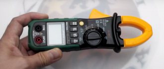
You can also use a multimeter to measure current. Before taking measurements, you must read the instructions for the specific multimeter model in order to properly configure it and connect it to the electrical circuit.
How does an ammeter work?
There are two types of ammeters: analogue, which indicate the value by deflecting the needle of a mechanical device, and the increasingly used digital instruments, equipped with complex electronic circuits.
When making analog ammeters, it is necessary to use effects that depend on the magnitude of the electric current. Most often they are associated with the creation of a magnetic field by a conductor in which an electric current flows. The higher the current, the greater the effect produced by this phenomenon.
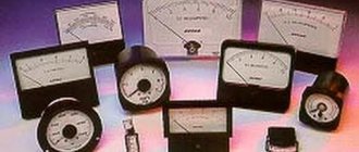
Each analog ammeter has a moving and a stationary part. An arrow is attached to the moving part, which moves along the scale and allows you to read the readings of the device. To avoid reading errors that are caused by the parallax effect, you should look at the needle at a right angle to the scale, which is facilitated by a mirror located next to the scale (see Figure 1).
Rice. 1. Indicating microammeter with a mirror installed to reduce the parallax effect when taking readings
Ammeter
An ammeter is a device for measuring current in an electrical circuit.
In terms of operation and appearance, an ammeter is very similar to a galvanometer. Its design has been modified so that it is possible not only to detect the presence of current in the circuit, but also to measure its strength .
In what units is the ammeter scale calibrated? Since it measures current, its scale will be graduated in amperes .
Different types of ammeters may differ from each other depending on the application. Figure 1, a shows a demonstration ammeter . Such devices are most often used in schools when demonstrating experiments.
Figure 1, b shows an ammeter, which is often used for laboratory work.
Figure 1. Demonstration and laboratory ammeters
As you can see, these two ammeters are designed to measure a specific range of current values. The scale of the first ammeter will show a maximum value of $3 \space A$, and the second - $2 \space A$. It is not recommended to exceed these values, as the devices may fail.
Types of ammeters, their design and principle of operation
Each type of ammeter uses different physical phenomena associated with the flow of electric current through a conductor. Some of them are listed below.
Magnetoelectric ammeter
- A conductor with electric current placed in a magnetic field is subject to an electrodynamic force, the magnitude of which depends on the absolute value of the electric current, the length of the conductor and the magnitude of magnetic induction.
The design of a magnetoelectric ammeter based on this phenomenon is shown in Fig. 2. The rotating coil through which the measured electric current flows is marked in red. The parts of the coil perpendicular to the plane of the pattern are used as a conductor.
The magnetic field is created by a permanent magnet shaped so that the field is radial. Thus, each fragment of the interacting conductor is always perpendicular to the magnetic field induction vector, regardless of the position of the coil with the pointer.
Rice. 2. Scheme of operation of a magnetoelectric ammeter. The red color is the coil in which the current flows, the green color is the spring.
The formula describing the force of magnetic interaction acting on a straight conductor with a current placed in a magnetic field is: F = I * L * B (1), where:
- L is a vector along the conductor with a value equal to its length and a direction the same as the direction of flow of electric current;
- B is the magnetic field induction vector.
According to this formula, a force acts on current-carrying conductors perpendicular to the plane (see Figure 2), the direction of which is perpendicular to both these conductors and the magnetic field induction vector. This force causes the coil to rotate. The value of the force, according to formula (1), is equal to F = I * l * B * sin α (2), where:
where α is the angle between the directions of the vector L and the magnetic field induction vector B. As mentioned above, this angle is always equal to 900 if the magnetic field is radial.
The spring, indicated in green in Figure 2, counteracts the rotation of the coil in such a way that an equilibrium position is established depending on the current strength, the value of which can be determined by the arrow located above the ammeter scale.
Thus, the described ammeter shows the direction of flow of electric current. It can only be used for constant or unidirectional current. This is, in particular, the design of galvanometers.
Electrodynamic ammeter
- Two coils carrying electric current interact with each other through magnetic interaction.
An electrodynamic ammeter consists of two coils - movable and stationary (see Figure 3).
Rice. 3. The device of an electrodynamic ammeter. 1 - fixed coil, 2 - moving coil, 3 - spring
If an electric current is flowing through both coils, the value of which we want to measure, the magnetic fields will interact, causing the moving coil and the pointer (arrow) attached to it to deflect. This effect does not depend on the direction of flow of electric current. An electrodynamic ammeter can be used to measure direct and alternating current, including rapidly changing current. These are precise devices, but expensive. They are most often used in laboratories as reference measuring instruments.
Induction ammeter
- In a metal rotating disk, eddy currents are induced by magnetic fields created by coils in which an alternating electric current flows.
Electric currents I1 and I2 (see Figure 4) flowing in the coils of the electromagnets create pulsating magnetic fluxes, which cause eddy currents in the disk placed in the air gap of the electromagnets.
The eddy currents also create a magnetic field that interacts repulsively with the field of the coil, causing the disk to rotate.
Rice. 4. Induction ammeter device
An inductive ammeter can only be used to measure alternating current, because DC current will not cause eddy currents in the disk. This type of design is currently only used as electricity meters.
Rules for connecting an ammeter to an electrical circuit
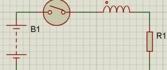
- The ammeter must be connected in series with the device/conductor in which the current is to be measured (Figure 3)
Figure 3. Series connection of an ammeter to an electrical circuit
- The ammeter has two terminals for connecting conductors. The terminal with the “+” sign must be connected to the wire coming from the positive pole of the current source. And, accordingly, the terminal with the “-” sign must be connected to the wire coming from the negative pole of the current source (Figure 4).
Figure 4. Correct connection of the ammeter, taking into account the positive and negative poles of the current source
- You cannot connect an ammeter to a circuit in which there is no current consumer (receiver) (Figure 5). This may cause the device to malfunction.
Figure 5. Impossibility of connecting an ammeter to a circuit without an electricity consumer
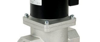
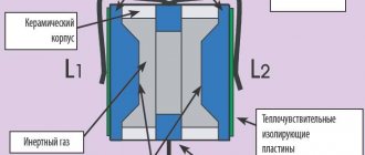
Purpose and design features of instrument transformers
Step-down blocks are used in measuring and computing systems. They have one main and several additional coils. Ammeters are connected to a secondary circuit, where the primary and secondary currents are directly proportional to each other. The current strength depends on the number of turns and the internal resistance of the wire. This voltage is safe for operating personnel and allows work to be carried out without risk to life.
The windings of the measuring units are made on a ferrite rod. When voltage is applied to the main coil, a magnetic field is generated that varies in space. Such oscillations generate electromotive force in the secondary windings.
Measuring current with an ammeter
The first rule for connecting an ammeter to a circuit is that it is connected in series. Is there a difference where exactly with this connection we place the ammeter?
Let's assemble an electrical circuit. It will consist of a current source, a key, a light bulb and an ammeter (Figure 6).
Figure 6. Series connection of an ammeter (option No. 1)
After closing the circuit, we record the current strength shown by the ammeter.
Now let's move the ammeter in the circuit so that it stands after the lamp, and not before it (Figure 7).
The ammeter will show us the same current value as in the previous case.
Figure 7. Series connection of an ammeter (option No. 2)
Now let’s connect two ammeters to the circuit at once (Figure 8). And what will we see? They will show the same current values , exactly the same as in previous experiments.
Figure 8. Series connection of two ammeters in an electrical circuit
What does this tell us?
In a circuit with a series connection of conductors (so that the end of one conductor is connected to the beginning of another), the current strength in all parts of the circuit is the same.
Why is it the same? The fact is that the charge that passes through any cross section of the conductors of the circuit in $t = 1 \space s$ is the same. After all, the current flows evenly through all the wires of the circuit, without accumulating anywhere. Its flow can be compared to the flow of water through pipes.
Safe and dangerous current limits
Working with electrical circuits can be dangerous if safety instructions are not followed. If we are talking about direct current (the magnitude of the current and its direction do not change over time), then the effects of such current on the human body are shown in Table 1.
| $I$, $ma$ | Impact on the human body |
| 0 — 3 | Not felt |
| 4 — 7 | Itching. Warming sensation |
| 8 — 10 | Increased heating |
| 11 — 25 | Even more intense heating, slight contractions of the arm muscles |
| 26 — 80 | Strong feeling of heating. Contractions of the arm muscles. Convulsions, difficulty breathing. |
| 81 — 100 | Respiratory paralysis |
Table 1. Effect of direct current on the human body
Why control the charge current in the battery?
The use of a measuring device can be considered using the example of a typical technological operation. A serviced car battery is infected using a special technique. Set and maintain the current value at 10% of the capacity specified in the passport data. This prevents excessive release of explosive gases. The duration of the procedure (24 hours or more) implies the need to supplement the device with automatic shutdown means.
Using the information provided, you can independently select a suitable device, perform measurements, and assemble a shunt circuit. At the preliminary preparation stage, the expected operating range and operating conditions should be clarified. When purchasing, it is recommended to study the manufacturer's official instructions.
Exercises
Exercise No. 1
When the ammeter was connected to the circuit as shown in Figure 9, a, the current strength was $0.5 \space A$.
What will be the readings of the ammeter when it is connected to the same circuit as shown in Figure 9, b? Figure 9. Options for connecting an ammeter to an electrical circuit
The current strength will be exactly the same. The ammeter will show a value of $0.5 \space A$. This is explained by the fact that in this electrical circuit all elements are connected in series. In this case, the current strength in all sections of the circuit is the same.
Exercise No. 2
How can you check the accuracy of an ammeter reading by using another ammeter that has been verified to be accurate?
It is possible to assemble a circuit as in Figure 6 using an accurate ammeter. Record the current value that it will show. Then replace it with another one, the one whose accuracy we want to check. Next, all that remains is to simply compare the readings of this ammeter with those obtained earlier.
You can do this in another way. To do this, you need to assemble a circuit, as in Figure 8, with serial connections of all elements. We already know that in such a circuit two working ammeters should show the same values . The main thing during such a check is to note for yourself which ammeter shows accurate measurement results, so as not to get confused.
Exercise #3
Consider the ammeters given in Figure 1. Determine the scale division value of each ammeter.
What is the highest current they can measure? Redraw the ammeter scale (see Figure 1, a) in your notebook and show what the position of the arrow will be at a current strength of $0.3 \space A$ and $1.5 \space A$. The scale of the demonstration ammeter from Figure 1, a, will have a division value equal to $0.2 \space A$.
The scale of the laboratory ammeter from Figure 1, b will have a division value equal to $0.05 \space A$.
In Figure 10, a we depicted the scale of a demonstration ammeter, which shows the value $I = 0.3 \space A$, and in Figure 10, b - $I = 1.5 \space A$.
Figure 10. Current values on the ammeter scale
How to choose a transformer
When choosing a converter, you must always take into account the load created by current consumers. Their simultaneous inclusion in the network increases the power several times, which leads to heating of the power supplies. The main characteristics are always written on the nameplate, so the voltage rating required to provide electricity is calculated using the formula I1+I2+…In, where I is the current consumption of the electrical appliance.
It is also necessary to take into account the accuracy class of the object, which will allow accurate accounting of energy consumption.