General information
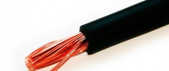
Transformer welding machines are relatively inexpensive and easy to repair due to their simple design. However, they are heavy and sensitive to supply voltage (U). When U is low, it is impossible to carry out work, since significant changes in U occur, as a result of which household appliances may fail. In the private sector, there are often problems with power lines, since in the former CIS countries most power lines require cable replacement.
The electrical cable consists of twists, which often oxidize. As a result of this oxidation, an increase in the resistance (R) of this twist occurs. Under significant load, they heat up, and this can lead to overload of power lines and transformer substation. If you connect an old-style welding machine to an electricity meter, then when U is low, the protection will be triggered (“knock out” the machines). Some people try to connect the welder to the electricity meter, breaking the law.
Such a violation is punishable by a fine: electricity is consumed illegally and in large quantities. In order to make work more comfortable - not to depend on U, not to lift heavy objects, not to overload power lines and not to break the law - you need to use an inverter-type welding machine.
Manufacturing of transformer and choke
The main task of the transformer is to convert the voltage of high-frequency current with sufficient strength. The cores can be used model Ш20×208, in the amount of two pieces. You can create the gap between the parts yourself using plain paper. The winding is made with your own hands, with a copper strip 40 mm wide, the thickness should be at least 0.2 mm. Thermal insulation is achieved using cash register thermal tape; it demonstrates good wear resistance and strength.
How to make a transformer for an inverter
The use of copper wire when winding the core is unacceptable, because it forces current onto the surface of the device. To remove excess heat, a fan or cooler from the computer power supply, as well as a radiator, are used.
The inverter unit is responsible for the throughput of the electric arc through the use of transistors and chokes.
For a stable welding process, it is recommended to use several transistors in a parallel circuit rather than one more powerful element.
Due to this, the output current is stabilized; during the process of inverter welding with your own hands, the device produces less noise.
Homemade choke
Capacitors connected in series are responsible for several functions:
- Resonant emissions are minimized.
- Ampere losses due to the design features of transistors, which open much faster than they close.
Homemade transformer as the basis for an inverter
Transformers get very hot due to the large volume of passing current. Radiators and fans are used to control the temperature. Each element is mounted on a radiator made of heat-dissipating material; if it is possible to install one powerful cooler, this will reduce assembly time and simplify the design.
Device and principle of operation
The welding inverter is designed so that it is suitable for both home use and enterprise use. With small dimensions, it is capable of ensuring a stable burning of the welding arc and even using a welding current that is significantly higher than that of an ordinary welding machine. It uses high-frequency current to generate a welding arc and is an ordinary switching power supply (the same as a computer one, only with higher current), which makes the circuit of the welding machine simple.
The basic principles of its operation are as follows: input voltage rectification; conversion of rectified U into high-frequency alternating current using transistor switches and further rectification of alternating U into high-frequency direct current (Figure 1).
Figure 1 - Schematic design of an inverter-type welder.
When using high-power key transistors, direct current is converted, which is rectified using a diode bridge into high-frequency current (30..90 kHz), which makes it possible to reduce the dimensions of the transformer. A diode rectifier allows current to flow in only one direction. The negative harmonics of the sinusoid are “cut off”.
But the rectifier output produces a constant U with a pulsating component. To convert it into a permissible direct current in order to ensure the correct operation of key transistors operating only on direct current, a capacitor filter is used. A capacitor filter is one or more high-capacity capacitors, which can significantly smooth out ripples.
The diode bridge and filter make up the power supply for the inverter circuit. The input of the inverter circuit is made using key transistors that convert DC U into high-frequency AC (40..90 kHz). This transformation is needed to power a pulse transformer, the output of which produces a high-frequency current of low U. A high-frequency rectifier is powered from the outputs of the transformer, and a high-frequency direct current is generated at the output.
The device is not very complicated, and any inverter welder can be repaired. In addition, there are many schemes by which you can make a homemade inverter for welding work.
Assembling the inverter unit
To make a welding inverter with your own hands, you need to move on to the next stage - installing the inverter unit. Since this node converts current from direct to alternating, powerful transistors are needed that will open and close, creating a high frequency.
In the instructions for making a simple inverter, you can include a diagram of the inverter unit.
Immersion blender - which company is better to choose for your home? Photo+video reviewsDIY tester: instructions, diagrams and solutions on how to make a simple homemade device. Step-by-step instructions on how to make a tester from a smartphone
DIY voltage regulator: master class on how to make a simple voltage regulation device
It makes sense to mount this unit using several transistors so that the frequency is more stable and the machine hums less when welding.
Homemade welding machine
Assembling an inverter for welding is easy, since there are many schemes. It is possible to make welding from a computer power supply and knock down a box for it, but you will end up with a low-power welder. Details about creating a simple inverter from a computer power supply for welding can be found on the Internet. An inverter for welding using a PWM controller such as UC3845 is extremely popular. The microcircuit is flashed using a programmer, which can only be purchased at a specialized store.
Frame
Step-by-step assembly of an inverter with your own hands involves selecting a reliable housing for such a product. An old computer system unit is quite suitable for this purpose (the older the better, because the metal in it is thicker). You can make a box yourself from sheet metal, and use a half-centimeter or more getinax at the bottom.
Various types of homemade welding inverters have a common feature - this is the control of the operation of the device. A switch, a welding current adjustment knob, wiring contacts, and indicator lamps are installed on the front panel.
Thus, in order to acquire a device that is so necessary for a home workshop, it is not necessary to buy a ready-made inverter. You can study the necessary theory, purchase parts and assemble welding yourself that will work reliably.
Inverter manufacturing
Before starting the manufacture of a high-frequency transformer for the inverter, it is necessary to make a getinaks board, guided by Scheme 2. The transformer is made on a magnetic core of the “Ш20х28 2000 NM” type with an operating frequency of 41 kHz. To wind it (I winding), it is necessary to use copper sheet with a thickness of 0.3..0.45 mm and a width of 35..45 mm (the width depends on the frame). Need to do:
- 12 turns (cross-sectional area (S) about 10..12 sq. mm.).
- 4 turns for the secondary winding (S = 30 sq. mm.).
A high-frequency transformer cannot be wound with an ordinary wire due to the skin effect. Skin effect is the ability of high-frequency currents to be forced onto the surface of a conductor, thereby heating it. The secondary windings should be separated by fluoroplastic film. In addition, the transformer must be properly cooled.
The choke is made on a magnetic core of type “Ш20×28” made of 2000 NM ferrite with S of at least 25 sq. mm.
The current transformer is made on two rings of the “K30×18×7” type and is wound with copper wire. Winding l is threaded through the ring part, and winding II consists of 85 turns (d = 0.5 mm).
Scheme 2 - DIY inverter welding machine diagram (inverter).
After successfully manufacturing a high-frequency transformer, you need to install radio elements on a printed circuit board. Before soldering, treat the copper tracks with tin; do not overheat the parts. List of inverter elements:
- PWM controller: UC3845.
- MOSFET transistor VT1: IRF120.
- VD1: 1N4148.
- VD2, VD3: 1N5819.
- VD4: 1N4739A at 9 V.
- VD5-VD7: 1N4007.
- Two VD8 diode bridges: KBPC3510.
- C1: 22 n.
- C2, C4, C8: 0.1 µF.
- C3: 4.7 n and C5: 2.2 n, C15, C16, C17, C18: 6.8 n (only use K78−2 or SVV-81).
- C6: 22 microns, C7: 200 microns, C9-C12: 3000 microns at 400 V, C13, C21: 10 microns, C20, C22: 47 microns at 25 V.
- R1, R2: 33k, R4: 510, R5: 1.3 k, R7: 150, R8: 1 at 1 W, R9: 2 M, R10: 1.5 k, R11: 25 at 40 W, R12, R13 , R50, R54: 1 k, R14, R15: 1.5 k, R17, R51: 10, R24, R25: 30 at 20W, R26: 2.2 k, R27, R28: 5 at 5W, R36, R46- R48, R52, R42-R44 - 5, R45, R53 - 1.5.
- R3: 2.2 k and 10 k.
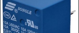
- K1 for 12 V and 40A, K2 - RES-49 (1).
- Q6-Q11:IRG4PC50W.
- Six IRF5305 MOSFET transistors.
- D2 and D3: 1N5819.
- VD17 and VD18: VS-HFA30PA60CPBF; VD19-VD22: VS-HFA30PA60CPBF.
- Twelve Zener diodes: 1N4744A.
- Two optocouplers: HCPL-3120.
- Inductor: 35 microns.
Characteristics of a homemade inverter and materials for its assembly
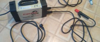
For the device to operate effectively, you need to use high-quality materials. Some parts can be used from old power supplies or found at disassembly sites for radio components.
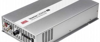
Main technical characteristics of the device:
- The voltage consumption is 220 Volts.
- The input current is at least 32 amperes.
- The current produced by the device is 250 A.
Assembly diagram of a welding inverter
The main circuit of a welding inverter consists of a power supply, chokes, and a power unit.
To make the device you will need tools and parts:
- A set of screwdrivers for dismantling and further assembly.
- A soldering iron is necessary for connecting electronic elements.
- A knife and a metal blade for making the correct shape of the structure.
- A piece of metal 5-8 mm thick to form the body.
- Self-tapping screws or bolts with nuts for fastening.
- Boards for electronic circuits.
- Copper products in the form of wires are used for transformer windings.
- Fiberglass or textolite.
In home use, a homemade single-phase type welding inverter, made by yourself, is popular.
Single-phase welding inverter
Such an inverter is powered from a 220 V household network; there are cases when it is necessary to manufacture a device whose power comes from a three-phase 380 V network. Such devices are characterized by increased efficiency and power and are used for mass work.
Basic recommendations
Before assembly, you need to carefully familiarize yourself with the inverter welding diagram and purchase everything necessary for manufacturing: buy radio components in specialized radio stores, find suitable transformer frames, copper sheet and wire, think about the design of the housing. Planning the work greatly simplifies the assembly process and saves time. When soldering radio components, you should use a soldering station (induction with a hair dryer) to avoid possible overheating and failure of radio elements. You must also follow safety rules when working with electricity.
Checking work
To check the device you need to use an oscilloscope. The inverter is connected to a 220 V network, and then the device is used to check whether the output parameters correspond to the required ones. For example, the voltage should be in the range of 500-550 V. With absolutely correct assembly and correctly selected parts, this value should not exceed the threshold of 350 V.
After such measurements and acceptable oscilloscope readings, you can begin making the weld. After the first electrode has completely burned out, it is necessary to measure the temperature on the transformer. If it boils, then the circuit needs to be improved, the device must be turned off and changes made. Only after measures have been taken to eliminate this defect, can you restart with the same temperature measurement after completion of work.
Example of inverter front panel layout
Bottom line
It is a mistake to assume that a device you create yourself will not allow you to effectively perform the necessary work. With a homemade device with an easy assembly circuit, you can weld elements using an electrode with a diameter of up to 5 millimeters and an arc length of up to 10 millimeters.
After the homemade equipment is connected to the circuit, it is necessary to set the automatic mode with a specific current value. The voltage in the wire may be about 100 volts, which indicates some kind of problem.
To fix the problem, you need to find the circuit diagram of the welding inverter, disassemble it and check how correctly it was assembled.
Thanks to such a homemade apparatus, the welder can not only weld homogeneous, dark metal, but also non-ferrous and various alloys. When assembling such a device, in addition to the basics of electronics, you also need to have a free period of time to implement your plan.
The welding process using an inverter is a necessary thing in every man’s home for any domestic and industrial purposes.
Operating rules
The welding inverter can be used both for welding parts made of ferrous metal and for working with non-ferrous metal. It is useful both in a private house, in a country house, and in a garage.
When operating it, it is necessary to monitor the quality of voltage and frequency in the network.
For long-term use of this unit, it is necessary to periodically check the performance of its individual cleanings and carry out preventive measures to clean it from dust and dirt.
Scheme
One of the first steps in manufacturing an inverter is determining its operating circuit. Since there is a large amount of choice on the Internet, there is no need to come up with something new.
We will continue to use information about the inverter model COLT1300 as a basis; the working diagram is shown in Figure 1:
Fig 1.
Figure 2 shows a diagram of the control unit for the processes taking place in the power section. For the type of device under consideration, the circuits are squeezed onto one board. Let's change this and make the control unit on a separate board.
Fig.2
Let's divide the main diagram into several parts and get:
Power section and transistor drivers:
Power supply:
Welding inverter with spike controller:
Inverter power supply:
To make electrical 4 boards, you will need the following:
- textolite FR4 150×250mm (2mm);
- permanent black marker;
- citric acid and hydrogen peroxide;
- soldering flux LTI-120;
- drill with a diameter of 1mm and 2mm;
In the Dip Trace program we draw a power circuit:
Convert to payment:
At the end you will get a drawing:
An example is shown in a simpler diagram. You can download a tutorial for working with Dip Trace on the Full-Chip.net website. It sequentially describes each operation for printing microcircuits.
The resulting image of the layout must be printed on a laser printer, this is a prerequisite, ink will not give the desired effect:
- Let's prepare the textolite. Sand lightly with fine-grit sandpaper to a bright surface. We attach the printed layout to the plate and wrap it with another layer of newsprint on top.
- Apply a hot iron and wait 15-20 seconds. Let it cool gradually, then soak it in water to make it easy to peel off. If in some area the connection is poorly printed, we fill it in with a black marker.
- Preparing a bath for etching the board. The solution includes citric acid, hydrogen peroxide and water. The container is large enough for the board to fit completely into it. You must be careful with this mixture and wear rubber gloves. Stir only with wooden objects, not metal ones.
- Then all this should be placed in a warm place or in a basin with warm water. By controlling the process, you can see when the unpainted copper coating comes off, then you can remove the part.
- Dry the diagram and remove the marker with sandpaper. We cover the surface with LTI-120 flux. In order to allow the tracks to oxidize, they must be carefully polished to a pleasant shine.
So, we get two boards for the power circuit and the control unit.
Do-it-yourself inverter welding is very simple
Inverter welding is a modern device that is widely popular due to the light weight of the device and its dimensions. The inverter mechanism is based on the use of field-effect transistors and power switches. To become the owner of a welding machine, you can visit any tool store and acquire such a useful thing. But there is a much more economical way, which is due to the creation of inverter welding with your own hands. It is the second method that we will pay attention to in this material and consider how to do welding at home, what is needed for this and what the diagrams look like.