In the operation of electrical circuits, situations constantly arise when it is necessary to turn on or off any installations and equipment from a distance. To solve these problems, electromagnetic contactors operating with different types of currents are widely used. In the normal operating mode of switching devices, such operations are expected to be performed frequently - approximately 1500 per hour. The design and operating principle of contactors allows them to be actively used to control high-power motors installed on electric locomotives, trams, trolleybuses, elevators and other machinery and equipment.
Difference between contactor and magnetic starter
Many people confuse contactors with starters. How do they differ from each other?
A contactor is essentially a single device designed to close and open electrical circuits. And the starter is a kind of complex device that performs the same function, but with additional elements in its circuit.
For example, various types of protection or trigger buttons.
The big problem is that many people use these terms differently.
The main thing is to understand the functionality of each equipment.
Structural elements
Each KMI contactor is equipped with a coil or electromagnet, which forms the basis of the device. This component is powered over a wide voltage range - 12-380 volts. Before connecting, you need to accurately set the operating current of the electromagnet, indicated in the passport or on the side of the coil body.
The next important design element is the core. It is a prefabricated structure with metal plates impregnated with varnish. The core consists of fixed and moving parts. The first part is used to accommodate the coil, and the other part - the movable one - is intended to accommodate the movable contacts. The fixed contacts are secured using screws to the plastic body of the device. Movable – attached to the core with a special insulating holder. Short-circuited aluminum rings are pressed into the pole tips of the stationary part, eliminating the effect of detonation.
The contact area of the contact solders in different IEC designs may differ. It depends on the operating current of the power circuits, which can be passed by the contactor. In this regard, each type of device has its own value - first, second, third, etc. Most of them are equipped with four contact pairs: three are intended for the power circuit, and one is additional and performs various functions. It blocks the control circuit, turns on a sound or color alarm, and partially provides automatic relay protection for the control of electrical installations.
The conductors are connected using special connecting contacts. They have an oval shape, which increases the reliability of fixation. For small wires, hardened disc washers are used, and for large conductors, a clamping clamp is provided. Notches on the contacts further increase the reliability of fixation, increase the contact area and reduce heating of the wires.
When power is applied to the coil, it results in an electromagnetic effect. Under its influence, the metal cylinder begins to move upward, after which the contact closes. The circuit supplying power to the coil is considered the control circuit, and the voltage in it is quite low, within 24 volts. The other circuit that closes the contact is a power circuit, since a current with a voltage of up to 660 volts passes through it. In the absence of power supply, the metal core returns to its original position under the action of a spring, and the circuit is open.
What do the abbreviated names of starters mean?
Below are explanations of the symbols and names of popular brands of starters and contactors PML, KME, PAE, PMA.
From them you can find out what certain alphanumeric symbols mean and how they are deciphered.
It turns out that just from the name alone you can understand:
- what product is this
- what functionality does it have?
- what additional capabilities does it contain?
To view each starter type, click on the appropriate tab.
PMLKMEPAEPMA
However, in addition to the name, a lot of information is contained on the contactor body itself.
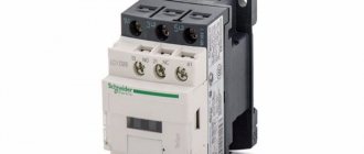
Let's look at the example of two products from IEK KMI and Schneider Electric LC1D25, what inscriptions and designations manufacturers put on the housings, how they are deciphered and what they mean.
Main product advantages
The magnetic contactor from Schneider Electric has a number of advantages in comparison with analogues:
- — operating temperature range is above average – from -50 to +50 degrees Celsius;
- — extended range of rated current;
- — simplified installation thanks to special screwless clamps;
- — low noise during switching;
- — resistance to shock and vibration;
- — economical energy consumption;
- — the contactor additionally protects against voltage surges thanks to the built-in Transil diode;
- - increased durability and wear resistance, which is determined by the use of innovative developments.
Technical specifications on the contactor itself
Let's start with the contactor from Schneider Electric. The maximum possible power connected to the contactor in horsepower (HP) is indicated on the side edge. This power depends on the supply voltage.
In a number of countries, horsepower is still used, although there are recommendations from the international metrology organization that horsepower should be eliminated from use.
The following are general recommendations for selecting circuit breakers or fuses.
- the inscription CB - Circuit Breaker refers to automatic machines
- Fuse – to fuses
The maximum operating voltage (a.c. max) must be specified.
Cont. current is the continuous rated current at load category AC1.
To put it simply, category AC1 is a load such as an iron or an ordinary heater.
AWG 6-14 Cu - shows the cross-section of wires that can be connected to the contacts.
Measurements are in Western units. In order to find out the analogue of our section in mm2, you will need to use the AWG to mm2 conversion table.
Torque 20lb.in – the torque with which the terminals can be tightened.
More accurate numbers in conventional units of measurement can also be found in the technical data on the manufacturer’s website, or use a special program here that converts lb-in to Nm (newton meters).
Lb-in stands for pounds per square inch.
High-quality contactors always have inscriptions indicating the presence of certificates to which this mechanism corresponds.
Ith-40A – conditional thermal current in open design. Simply put, this is the current that the contactor can pass through itself under normal environmental conditions.
Ui=690V – rated insulation voltage of the product.
IEC/EN 60947-4-1 – starter compliance with this standard. GOST R50030.4.1-2012 is our modified analogue of this standard.
Uimp=6kV – permissible pulse overvoltage.
A separate plate indicates the possible powers connected to the contactor, depending on the supply voltage.
Powers are already registered in kilowatts. Some may wonder why there is such a difference depending on the voltage.
This is explained simply. By and large, the contactor does not care what voltage the load is designed for. The most important thing is the amount of current flowing through its contacts.
For example, you have a voltage of 100V and a current of 10A. The load in this case will be 1 kW.
And if the voltage is 2 times greater, i.e. 200V, then when connecting the same load of 1 kW, a current will flow through the product 2 times less than I = 5A.
Therefore, the lower the voltage, the less power the load can be connected to the contactor. At the same time, always pay attention to what type of load the data is indicated for.
For example, in this case, the powers are indicated for the AC3 load. An example of such a load is an asynchronous motor.
JIS C8201-4-1 is a Japanese industrial standard. Accordingly, the possible powers connected to the contactor are also specified here, depending on the supply voltage according to this standard.
Why is such a large and strange set of voltages prescribed? Because different countries have different standards that determine power voltage levels.
For example, in Japan, a regular outlet has 100 volts. And for powerful loads, 200V is already used.
Switching device
The contacts of the device are subject to the most severe mechanical and electrical wear. This is due to the large number of on/off operations per hour. To reduce wear on the contact surface, linear rolling contacts have become more widespread.
To avoid vibration of the contacts, the contact spring creates a pre-pressure that is approximately half the final pressing force. Vibrations are greatly influenced by the rigidity of the fastening, both of the electrical contact itself, and the vibration resistance of the entire contactor as a whole. In this regard, a good example is the design of the KPV-600 contactor (figure below).
The movable contact 1 is rigidly attached to bracket 2. One end of the arc extinguishing coil 3 is attached to the same bracket. The second end of the coil and terminal 4 are securely attached to an insulated plastic base 5. The latter is attached to a strong steel bracket 6, which is the base of the device. The movable contact 7 is made in the form of a thick plate 7. The lower end of the plate can be rotated relative to the fulcrum 8. Thanks to this property, the plate can roll over the block of the fixed contact 1. Pin 9 is connected to the movable contact 7 using a flexible connection (conductor) 10. Contact pressure creates spring 12.
If the contacts are worn, the crayon 1 is replaced with a new one, and the plate can be turned 1800 and its undamaged side can be used for work, which leads to certain savings on replacing the plate.
Arc extinguishing horns (contacts) 2.11 are used to reduce melting of the main contacts at currents above 50 A. The arc reference points, under the influence of the magnetic field of the arc extinguishing device, quickly move to the bracket 2, which is connected to the fixed contact 1, and to the protective horn of the movable contact 11. Spring 13 returns the armature to its initial position (after the magnet is turned off).
The rated current is the main parameter of the contactor. It, in fact, affects the size of the device.
A characteristic feature of not only the KPV-600 contactor, but also of many other types, is the electrical connection of the moving element with the contactor body. The magnetic core is energized when the contactor is in the on position. Contact with the magnetic core is life-threatening, since voltage can remain on the magnetic core and other parts even in the off position of the contactor.
The KPV series of contactors has a design with an opening main contact. The contact is closed by a spring, and opened by an electromagnet.
The rated current of the contactor is the current of intermittent-continuous operation. In this mode, the contactor is in the on position for no more than 8 hours, after which the device must be turned on and off several times (necessary to clean the contacts from copper oxide). After which the device starts working again.
If the contactor is located in a control cabinet, the rated current is reduced by 10% due to deteriorating cooling conditions.
When turned on for more than 8 hours (long-term operation), the permissible contactor current is reduced by approximately 20%. In this operating mode, due to the oxidation of copper contacts, the contact resistance increases, which can lead to an increase in temperature above the permissible level. If the contactor is intended for a small number of switching operations or long-term switching, then a silver plate is soldered onto the working surface of the contacts. The silver lining allows you to maintain the operating current of the contactor at the rated level and in continuous operation. If, in addition to continuous operation, the contactor is also used in intermittent mode, the use of silver plates loses its meaning, since silver has low mechanical strength and with frequent switching on/off, the silver plate quickly wears out.
At duty cycle = 40% (intermittent duty), the permissible current, as a rule, is approximately 120% of the rated current. For the KPV-600 contactor (according to the manufacturer’s recommendations), the intermittent current is calculated using the formula:
Here n is the number of starts per hour.
It is important to note that if, in intermittent mode, when the load is disconnected, the electric arc burns for a long time (large inductive load), the temperature of the contacts will increase sharply due to heating by the arc. In this case, the heating of the contacts in intermittent operation may be higher than in long-term operation.
As a rule, the contact system has one pole.
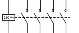
The double contact system is used for reversing asynchronous electric motors with a large number of starts per hour (more than 1200). Contactors of the KTPV – 500 type, which have a DC electromagnet, the moving contacts are isolated from the body, which has a positive effect on the safety of the device during maintenance. The figure below shows the contactor connection diagram for reversing asynchronous electric motors:
The two-pole circuit has a great advantage over the single-pole circuit. If one of the contactors fails, voltage will be supplied to only one phase of the motor. In the case of a single-pole system, the failure of one of the contactors will lead to the occurrence of two-phase power supply to the asynchronous motor, which is a difficult operating mode for the machine.
Also, contactors with two-pole power supply are quite successfully used to short-circuit the resistances in the rotor circuit of an asynchronous electric motor with a wound rotor.
The two-pole system is also used in contactors of the KTPV - 521 type. This type of contactor is intended for switching on and off DC drives of oil circuit breakers. The presence of a two-pole contact system ensures reliable disconnection of the inductive load.
Contact labels
Let's move on to the inscriptions on the front panel of the starter = contactor.
A1 and A2 are the control coil connection points.
The terminals themselves are marked in two alternative ways:
- number sequence 1-2-3-4-5-6
- alphanumeric. Top L1-L2-L3. Bottom T1-T2-T3.
Auxiliary contacts are marked in accordance with standards. There is one nuance that not everyone knows about.
Design
Structurally, the electromagnetic contactor consists of two main blocks:
- Bottom (base) - this block consists of a cover, inside of which there is an W-shaped fixed magnetic circuit with a control coil in the central part. The number of turns and dimensions of the control coil depend on the voltage applied to it. Thus, in Soviet and modern models of these devices, coils designed for voltages from 24 to 380 V can be installed.
- Upper (contact group) - this block includes two types of contacts: movable and fixed. Spring-loaded movable contacts are located on a traverse with a fixed magnetic circuit (core) having the same shape and dimensions as that installed in the base. In this case, the cores of the base and contact group, identical in shape and size, are located opposite each other.
Two groups of fixed contacts are located on both sides of the movable traverse and secured in special grooves with screws. One group of such contacts is supplied with power cables that are under the voltage required to power the load. The second group of contacts is connected to the operating circuit - the cables that power the load.
Since sparking often occurs when connecting relay contacts, the entire upper part of the device is covered with a special cover that acts as a spark arrester.
PML contactor design
Between the upper and lower blocks there is a return coil or leaf spring.
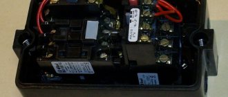
On a note. For safety and more convenient control of the device, it is often placed in a sealed case with two buttons: “Start” and “Stop”. Some models often have a third button – “Reverse”.
Normally open and closed contacts
The first digit of the designation is the serial number of the contact. And the second digit is the contact function.
For example, at the top you can see the inscriptions 13-21. Bottom 14-22.
That is, the first numbers 1-2 are the serial number of the contact. There is one auxiliary contact on the left, and a second on the right.
And the second number is the function. The number 1-2 is the common wire or part of the normally closed contact of the circuit.
The number 3-4 is part of the normally open contact. That is, by looking at the numbers, without unwinding or ringing the mechanism, without studying its diagram in the passport, you can immediately understand that 13-14 is normally open contact No. 1 (NO - normal open).
A 21-22 – normally closed contact No. 2 (NC – normal closed).
All other electromagnetic relays familiar to us have the same markings, making it easier to visually understand the functionality of the device. Here is an example of another relay and the designation of its contacts.
You don’t need to look for documentation for it to understand how to connect here or what function this or that screw terminal has.
The voltage of the coil that controls the starter is also required to be written on the housing.
The letter M7 (or another) is a definition of the coil type in the order number.
For example, if a coil burns out in your LC1D25 contactor, you will only need to indicate the voltage and its number M7 when ordering. You will know for sure that exactly the product will arrive, and the size you need.
Another important point that is worth paying attention to is the possibility of using different types of wires in the terminals. If the pads are copper, this means that it is unacceptable to use aluminum wires.
The cross-section and types of connected wires are indicated in the technical documentation.
Areas of use
Among the leaders in the production of safety electrical equipment and automation equipment, Schneider Electric is deservedly considered one of the most reliable and progressive. Modular contactors are widely used in industrial production, trade and in everyday life.
This type of electrical equipment is most in demand for energy supply and installation:
- — ventilation and air conditioning systems;
- — lighting systems;
- — valves;
- — automatic gates, doors, etc.
All magnetic contactors can be divided into two categories, differing in their design features and capabilities:
- - reversible;
- - irreversible.