In lamps and flashlights, two circuits are used - serial and parallel connection of LEDs. These schemes have a lot of variations and combined options, each of them has its own advantages and disadvantages.
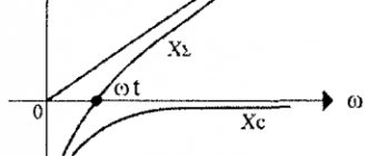
To understand which connection diagram is better, you need to find out what the current-voltage characteristic is and what it is like for an LED.
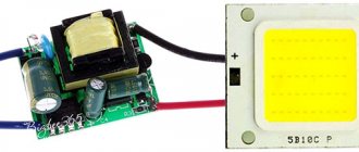
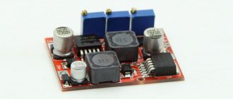
The photo shows an LED matrix for connecting to a 220V network
Some tips for creating a garland
When choosing the color of your future Christmas tree decoration, you should not pay attention to the RGB elements.
Assembly for a novice craftsman can become too complicated, and spending extra money to later connect them like ordinary components will be an unaffordable luxury. It is best to connect LEDs of different colors in parallel. Of course, you will have to make additional calculations of the resistor parameters, but the result will be much more interesting than when using single-color emitters. It is clear that a ready-made LED garland in a store is quite cheap. But you should understand that a product made by yourself will seem many times more beautiful. And the satisfaction that everything turned out as planned cannot be measured by any money.
When making such decorations, you should be extremely careful to ensure that there are no bare areas left and that the wires inside the controller do not overlap. The contacts must be properly soldered to avoid heating. It is necessary to understand that it will be located on the tree, and the needles flare up very quickly due to the resin it contains.
It makes sense to replace the power cable running from the controller to the socket - Chinese manufacturers are trying to save on everything. It is for this reason that the strands of this wire are slightly thicker than a hair. After opening the controller case, it makes sense to check the quality of soldering connections and contacts - in cheap models this is a sore spot.
conclusions
Increasing the voltage of the VAZ-2114 generator with your own hands is real and quite simple. At the same time, the cost amounted to 500 rubles . It is worth noting separately that if you do not have the necessary skills or abilities to work with automotive electronics, then you should contact a car service center, where everything will be done quickly and efficiently, and of course, at the expense of the car enthusiast.
Many motorists have encountered the concept of low voltage in the network. The culprit of the situation was the generator, which produced an insufficient amount of current. Is there any way to increase the voltage produced by the unit? How to increase the power of the generator without damaging the circuit and the overall system.
Parallel connection of LEDs
Here we have the opposite. The current must be multiplied by the number of LEDs, and the voltage drop must be calculated only once. Current strength: I = 0.025 * 15 =0.375 A We will need a power source capable of delivering a maximum current of 0.375 A. Let’s round it up to 0.35 (remember that it’s better to “underfill”?). In terms of voltage, we also fit in: 12 - 2 = 10. It remains with a large margin.
An inquisitive reader who stumbled a couple of paragraphs earlier may exclaim: “Wait! So why do we need 12 volts if we can get by with five?” "Can!" - we will answer him. But don’t rush to conclusions, this is not the end.
We decided that the LEDs will be connected in parallel. It is necessary to limit the current in the circuit. Let's say we don't have a special driver. Let's take a resistor. Let's calculate the required resistance using the long-known formula: 12 V / 0.35 A ~ 35 Ohm. Let's connect it between the power source and the anodes of the LEDs:
Incorrect parallel connection of three LEDs
That, it would seem, is all. But there is a problem:
How to connect to 12 volt car
Connecting LEDs to the vehicle's on-board network does not differ significantly from connecting to other power sources. Just don’t forget that a car’s battery in normal condition produces not 12 Volts, but approximately 14 Volts.
Even when connecting, you must remember that not every car has an on-board voltage stabilization system that works reliably.
Therefore, when calculating quenching resistors, it is better to take the supply voltage equal to 15 - 17 volts. This will somewhat reduce the brightness of the glow, but will significantly extend the service life, since the LED will operate in a “gentle” mode. No tags for this post.
YOU CAN'T DO THIS!!!
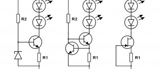
As noted above, LEDs do not necessarily have the characteristics stated by the manufacturer. There is always variation. And so we set the current to 0.35 amperes and look at the glowing line of LEDs. But they all need different current. One, as we calculated, 25mA, another - 20mA, the third 21mA, but we found a completely crooked LED, it only needs 15mA. And we pass 25 through it - almost 2 times more. The LED gets hot and burns out quickly. There is 1 less LED in the line. Now we need 35mA to power the remaining LEDs. So far, things don't look particularly bad. We have limited the current with a margin. We're great. But another LED failed. There are 13 left. Now all our current is divided not into 15, but into 13 LEDs. Each of them accounts for 26mA. Now absolutely all LEDs operate at increased current. Very soon the next one will overheat. The most persistent ones will receive 29 mA - 116% of the nominal value. Just 2 burned out LEDs started a chain reaction. Soon the entire line will burn out, and you will never understand why (or you will understand, we just sorted everything out). Actually, it’s easy to get rid of such a sad scenario. Each LED needs to have its own current-limiting resistor. For a current of 25mA and a voltage of 12V, a 480 Ohm resistor is needed. This will not save you from the problem of “crooked” LEDs, but their burnout will not affect the others in any way.
Advantages: highest reliability. Disadvantages: high current consumption, high cost of the circuit.
Correct parallel connection of three LEDs
Parallel connection of LEDs is ideal. Always try to connect LEDs in parallel and limit the current of each LED individually with its own resistor. If you use LED drivers (current stabilizers), then each LED needs to connect its own driver. This is why parallel circuits with many LEDs become too expensive. In reality, you have to make a compromise and combine LEDs into chains.
Create an account
Register a new account in our community. It's very simple!
This article discusses the possibility of using multiple Maxim Integrated MAX40200 integrated circuits (ICs) in parallel , as well as their combined parameters. Using multiple MAX40200 ICs together as an ideal diode should collectively provide the same performance as a single larger device.
Instead of an epilogue
Every self-respecting home craftsman must know which connection is called serial and which is parallel and be able to perform it. These skills will be useful not only when making garlands. You can encounter different types of connections anywhere. For example, in a home electrical network, all sockets are connected in parallel, while the switches are switched in series. The main thing is to remember the basic rules, follow them and be attentive to detail. In this case, any work that a home craftsman undertakes will be completed safely, reliably and at the proper level.
Mixed connection
This connection method is the most optimal. All LED strips are assembled using this principle. It involves a combination of parallel and serial connections. You can see how it is done in the photo:
The circuit involves connecting in parallel not individual LEDs, but serial chains of them. As a result of this, even if one or more chains fail, the LED garland or strip will still shine equally.
We looked at the main ways to connect simple LEDs. Now let's look at the methods for connecting high-power LEDs, and what problems you may encounter if connected incorrectly.
LED supply voltage
Despite the fact that the No. 1 electrical parameter for an LED is the rated current, it is often necessary to know the voltage at its terminals for calculations. The term “LED voltage” refers to the potential difference across the pn junction in the open state.
It is a reference parameter and, together with other characteristics, is indicated in the passport for the semiconductor device. 3, 9 or 12 volts... Often you come across specimens about which nothing is known. So how do you find out the voltage drop across an LED?
Theoretical method
An excellent clue in this case is the color of the glow, the external shape and dimensions of the semiconductor device. If the LED housing is made of a transparent compound, then its color remains a mystery, which a multimeter will help you solve.
To do this, turn the switch of the digital tester to the “check for break” position and touch the LED terminals one by one with the probes. A healthy element in forward bias will exhibit a slight glow from the crystal. Thus, we can draw a conclusion not only about the color of the glow, but also about the performance of the semiconductor device.
Light-emitting diodes of different colors are made from different semiconductor materials. It is the chemical composition of the semiconductor that largely determines the supply voltage of the LEDs, or more precisely, the voltage drop across the pn junction.
Due to the fact that dozens of chemical compounds are used in the production of crystals, there is no exact voltage for all LEDs of the same color. However, there is a certain range of values, which are often sufficient to carry out preliminary calculations of the elements of an electronic circuit.
On the one hand, the size and appearance of the housing do not affect the forward voltage of the LED. But in other way. through the lens you can see the number of emitting crystals that can be connected in series. The phosphor layer in SMD LEDs can hide an entire chain of crystals.
A striking example is the miniature multi-chip LEDs from Cree, whose voltage drop is often well above 3 volts. In recent years, white SMD LEDs have appeared, the housing of which contains 3 crystals connected in series. They can often be found in Chinese 220 volt LED lamps.
Naturally, it will not be possible to verify the serviceability of the LED crystals in such a lamp using a multimeter. The standard tester battery produces 9 V, and the minimum response voltage of a three-crystal white light-emitting diode is 9.6 V. There is also a two-crystal modification with a response threshold of 6 volts.
Practical method
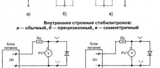
The most accurate data on the forward voltage drop across an LED can be obtained through practical measurements. To do this, you will need an adjustable DC power supply (PSU) with a voltage from 0 to 12 volts, a voltmeter or multimeter and a 510 Ohm resistor (more is possible). The laboratory circuit for testing is shown in the figure.
Everything is simple here: a resistor limits the current, and a voltmeter monitors the forward voltage of the LED. Smoothly increasing the voltage from the power source, observe the increase in readings on the voltmeter. When the triggering threshold is reached, the LED will begin to emit light.
At some point, the brightness will reach the nominal value, and the voltmeter readings will stop increasing sharply. This means that the pn junction is open, and a further increase in voltage from the output of the power supply will be applied only to the resistor. The current reading on the screen will be the nominal forward voltage of the LED.
If you continue to increase the power supply to the circuit, then only the current through the semiconductor will increase, and the potential difference across it will change by no more than 0.1-0.2 volts. Excessive current will lead to overheating of the crystal and electrical breakdown of the pn junction.
If the operating voltage on the LED is set to about 1.9 volts, but there is no glow, then the infrared diode may be tested. To verify this, you need to direct the radiation flow to the turned on phone camera. A white spot should appear on the screen.
In the absence of an regulated power supply, you can power the LED “crown” at 9 V. You can also use a 3 or 9 volt network adapter in the measurements, which produces a rectified stabilized voltage, and recalculate the value of the resistor.
Resistance formula for parallel and series connection
The flow of current in an electrical circuit is carried out through conductors, in the direction from the source to the consumers. Most of these circuits use copper wires and electrical receivers in a given quantity, having different resistances.
Depending on the tasks performed, electrical circuits use serial and parallel connections of conductors. In some cases, both types of connections can be used, then this option will be called mixed.
Each circuit has its own characteristics and differences, so they must be taken into account in advance when designing circuits, repairing and servicing electrical equipment.
Series connection of conductors
In electrical engineering, the series and parallel connection of conductors in an electrical circuit is of great importance. Among them, a series connection scheme of conductors is often used, which assumes the same connection of consumers. In this case, inclusion in the circuit is performed one after another in order of priority. That is, the beginning of one consumer is connected to the end of another using wires, without any branches.
The properties of such an electrical circuit can be considered using the example of sections of a circuit with two loads. The current, voltage and resistance on each of them should be designated respectively as I1, U1, R1 and I2, U2, R2. As a result, relations were obtained that express the relationship between quantities as follows: I = I1 = I2, U = U1 + U2, R = R1 + R2. The data obtained are confirmed in practice by taking measurements with an ammeter and a voltmeter of the corresponding sections.
Thus, the series connection of conductors has the following individual features:
- The current strength in all parts of the circuit will be the same.
- The total voltage of the circuit is the sum of the voltages in each section.
- The total resistance includes the resistance of each individual conductor.
These ratios are suitable for any number of conductors connected in series. The total resistance value is always higher than the resistance of any individual conductor. This is due to an increase in their total length when connected in series, which also leads to an increase in resistance.
If you connect n identical elements in series, you get R = n x R1, where R is the total resistance, R1 is the resistance of one element, and n is the number of elements. Voltage U, on the contrary, is divided into equal parts, each of which is n times less than the total value. For example, if 10 lamps of the same power are connected in series to a network with a voltage of 220 volts, then the voltage in any of them will be: U1 = U/10 = 22 volts.
Conductors connected in series have a characteristic distinctive feature. If at least one of them fails during operation, the current flow stops in the entire circuit. The most striking example is the Christmas tree garland, when one burnt out light bulb in a series circuit leads to failure of the entire system. To identify a burnt out light bulb, you will need to check the entire garland.
Parallel connection of conductors
In electrical networks, conductors can be connected in various ways: in series, in parallel and in combination. Among them, a parallel connection is an option when the conductors at the starting and ending points are connected to each other. Thus, the beginnings and ends of the loads are connected together, and the loads themselves are located parallel to each other. An electrical circuit may contain two, three or more conductors connected in parallel.
If we consider a series and parallel connection, the current strength in the latter can be studied using the following circuit. Take two incandescent lamps that have the same resistance and are connected in parallel. For monitoring, each light bulb is connected to its own ammeter. In addition, another ammeter is used to monitor the total current in the circuit. The test circuit is supplemented by a power source and a key.
After closing the key, you need to monitor the readings of the measuring instruments. The ammeter on lamp No. 1 will show the current I1, and on lamp No. 2 the current I2. The general ammeter shows the current value equal to the sum of the currents of individual, parallel-connected circuits: I = I1 + I2. Unlike a series connection, if one of the bulbs burns out, the other will function normally. Therefore, parallel connection of devices is used in home electrical networks.
I'm not alone
What I describe here is, without a doubt, a well-known practice. Now, if only those military industry developers had the habit of publishing their circuit designs on blogs... Here's what I came across on the Internet:
> > I believe it is pretty well standard practice to use an N-channel > > MOSFET in the return lead of military power supplies (28V input). > > Drain to supply negative, source to the negative of the PSU and > > the gate driven by a protected derivative of the positive supply.
Where to get MOSFETs for next to nothing
come see me a little later - there will be an article