If for an ordinary person the perception of information occurs by reading words and letters, then for mechanics and installers they are replaced by alphabetic, digital or graphic symbols. The difficulty is that while the electrician completes his training, gets a job, and learns something in practice, new SNiPs and GOSTs appear, according to which adjustments are made. Therefore, you should not try to learn all the documentation at once. It is enough to gain basic knowledge and add relevant data as you work.
Introduction
For circuit designers, instrumentation mechanics, electricians, the ability to read an electrical diagram is a key quality and indicator of qualification. Without special knowledge, it is impossible to immediately understand the intricacies of designing devices, circuits and methods of connecting electrical units.
Symbols can be considered a special cryptographic code that explains the operation and principle of operation of a particular scheme. In Japan, the USA and Europe, icons differ significantly from domestic markings, which must be taken into account.
Types and types of electrical circuits
Before you begin to study the existing symbols of electrical equipment and its connections, you need to understand the typology of circuits. On the territory of our country, standardization has been introduced according to GOST 2.701-2008 dated July 1, 2009, according to “ESKD. Scheme. Types and types. General requirements".
- United.
- Located.
- Are common.
- Connections.
- Installation connections.
- Completely principled.
- Functional.
- Structural.
Among the existing 10 species indicated in this document, the following are distinguished:
- Combined.
- Divisions.
- Energy.
- Optical.
- Vacuum.
- Kinematic.
- Gas.
- Pneumatic.
- Hydraulic.
- Electrical.
For electricians, it is of greatest interest among all the above types and types of circuits, as well as the most popular and often used in work - an electrical circuit.
The latest GOST, which came out, has been supplemented with many new designations, current today with code 2.702-2011 dated January 1, 2012. The document is called “ESKD. Rules for the execution of electrical circuits” refers to other GOSTs, including the one mentioned above.
The text of the standard sets out clear requirements in detail for electrical circuits of all types. Therefore, when performing installation work with electrical circuits, this document should be used as a guide. The definition of the concept of an electrical circuit, according to GOST 2.702-2011, is as follows:
“An electrical diagram should be understood as a document containing symbols of parts of a product and/or individual parts with a description of the relationship between them and the principles of operation from electrical energy.”
Once defined, the document contains rules for the implementation on paper and in software environments of contact connection designations, wire markings, letter designations and graphic representations of electrical elements.
It should be noted that most often only three types of electrical circuits are used in home practice:
- Mounting - for the device, a printed circuit board is shown with the arrangement of elements with a clear indication of the location, rating, principle of fastening and connection to other parts. Electrical wiring diagrams for residential premises indicate the number, location, rating, connection method and other precise instructions for the installation of wires, switches, lamps, sockets, etc.
- Fundamental - they indicate in detail the connections, contacts and characteristics of each element for networks or devices. There are complete and linear circuit diagrams. In the first case, control, control of elements and the power circuit itself are depicted; in a linear diagram, they are limited only to the circuit with the remaining elements depicted on separate sheets.
- Functional - here, without detailing the physical dimensions and other parameters, the main components of the device or circuit are indicated. Any part can be depicted as a block with a letter designation, supplemented by connections with other elements of the device.
Table 8
| Name | Designation |
| 1. The partition in the cable is gas-tight or oil-tight | |
| 2. The valve in the cable is gas-tight or oil-tight | |
| 3. Bypass gas-tight or oil-tight partition | |
| 4. Tank for air or oil under pressure | |
| 5. Pressure gauge with alarm contacts | |
| 6. Low pressure alarm device |
The designations of different devices are given in table. 9.
Graphic symbols in electrical diagrams
- 2.755-87 – graphic symbols of contact and switching connections.
- 2.721-74 – graphic symbols of parts and assemblies for general use.
- 2.709-89 – graphic symbols in electrical diagrams of sections of circuits, equipment, contact connections of wires, electrical elements.
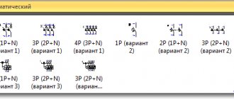
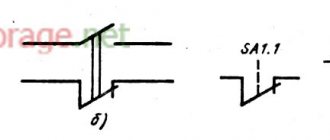
In the standard with code 2.755-87, it is used for diagrams of single-line electrical panels, conventional graphic images (CGI) of thermal relays, contactors, switches, circuit breakers, and other switching equipment. There is no designation in the standards for automatic devices and RCDs.
On the pages of GOST 2.702-2011, it is allowed to depict these elements in any order, with explanations, decoding of the UGO and the circuit diagram of the difavtomat and RCD itself. GOST 2.721-74 contains UGOs used for secondary electrical circuits.
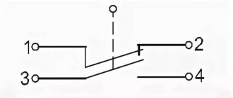
IMPORTANT: To designate switching equipment there is:
4 basic UGO images
| UGO | Name |
| Closing | |
| Breaking | |
| Switching | |
| Switching with neutral position |
9 functional signs of UGO
| UGO | Name |
| Arc suppression | |
| No self-return | |
| With self-return | |
| Limit or travel switch | |
| With automatic operation | |
| Switch-disconnector | |
| Disconnector | |
| Switch | |
| Contactor |
IMPORTANT: Designations 1 – 3 and 6 – 9 are applied to the fixed contacts, 4 and 5 are placed on the moving contacts.
table 2
| Name | Designation |
| 1. Remote control | C |
| 2. Power transmission | E |
| 3. Telephone communication | F |
| 4. Telemetry | M |
| 5. Broadcasting | R |
| 6. Transmission of sound (music) | S |
| 7. Stereo music streaming | SS |
| 8. Telegraph communication | T |
| 9. Data transfer | T.D. |
| 10. Video transmission | V |
| 11. Transmission of color television video signals | V.C. |
| 12. Video telephone communication | VF |
| 13. Transmission of monochromatic video signals | V.M. |
| 14. Examples of using designations for types of gears: - a line used for power transmission in one direction, telephone communication in two directions (simultaneously) and telemetering in one direction | |
| - a radio relay line used to transmit video signals and sound in one direction |
Designations for types of line laying are given in table. 3.
Basic UGO for single-line diagrams of electrical panels
| UGO | Name |
| Thermal relay | |
| Contactor contact | |
| Switch - load switch | |
| Automatic - circuit breaker | |
| Fuse | |
| Differential circuit breaker | |
| RCD | |
| Voltage transformer | |
| Current transformer | |
| Switch (load switch) with fuse | |
| Motor protection circuit breaker (with built-in thermal relay) | |
| A frequency converter | |
| Electricity meter | |
| Normally closed contact with reset button or other push-button switch, with reset and opening by means of a special actuator of the control element | |
| Normally closed contact with push-button switch, with reset and opening by retracting the control button | |
| Normally closed contact with push-button switch, reset and open by pressing the control button again | |
| Normally closed contact with push-button switch, with automatic reset and opening of the control element | |
| Delayed closing contact that initiates upon return and operation | |
| Delayed closing contact which only operates on return | |
| Delayed closing contact which is only initiated when triggered | |
| Delayed closing contact which is actuated by return and tripping | |
| Delayed closing contact which only operates on return | |
| Delayed closing contact that only switches when triggered | |
| Timing relay coil | |
| Photo relay coil | |
| Pulse relay coil | |
| General designation of a relay coil or contactor coil | |
| Indication lamp (light), lighting | |
| Motor drive | |
| Terminal (separable connection) | |
| Varistor, surge arrester (surge suppressor) | |
| Arrester | |
| Socket (plug connection): |
- Pin
- Nest
How does it work?
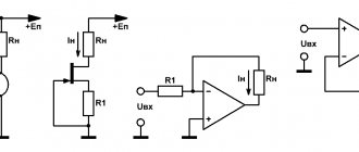
The operating principle of surge arresters is to reduce overvoltage by absorbing the inrush current released by varistors when their resistance decreases when an overvoltage occurs. Confusedly wrote, but I think now we’ll look into it in more detail and it will become more accessible.
To understand the operating principle of an arrester, consider the generalized current-voltage characteristic of a variable resistor.
Conventionally, it can be divided into three zones along the x-axis - a zone of low currents, a zone of medium currents and a zone of high currents. Along the axis, the game can also be divided into an operating voltage zone, a low voltage zone and an overvoltage zone.
In each of these areas, resistance behaves differently. In the first zone, the arrester is in working condition, the resistance of the resistors is high and a small current flows through the arrester.
When an overvoltage occurs, the varistor moves to section 2 of its current-voltage characteristic. The overvoltage creates a current pulse at the arrester, the resistors go into a conducting state, absorb the current pulse and dissipate it with thermal energy.
Due to the diverted current pulse, the overvoltage decreases and the resistor returns to zone 1. The same is true in zone 3, but there the bend in the curve is even greater and the current surge becomes even stronger.
Bookmark or share with friends
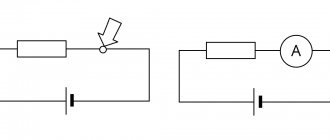
Designation of measuring electrical instruments to characterize circuit parameters
| A heating element |
| UGO | Name |
| PF | Frequency meter |
| PW | Wattmeter |
| PV | Voltmeter |
| PA | Ammeter |
GOST 2.271-74 accepts the following designations in electrical panels for buses and wires:
Table 5
| Name | Designation |
| 1. Intermediate double suspension | |
| 2. Hanging the wire (cable) on a cable | |
| 3. Wire (cable) self-supporting | |
| 4. Transposition of the line wire on the support | |
| 5. Transposition of the line wire between supports | |
| 6. Wire vibration damper | |
| 7. Capacitor bank on a support | |
| 8. Capacitor bank between supports | |
| 9. Pupinovskaya coil on a support | |
| 10. Control clamp on the support | |
| 11. Fuse on the support | |
| 12. Disconnector on support | |
| 13. Disconnector with fuse on support | |
| 14. Lamp on a support | |
| 15. Electro-acoustic devices on a support, for example, a loudspeaker | |
| 16. Lightning protection devices on a support: | |
| 16.1. Spark protection gap | |
| 16.2. Arrester. General designation | |
| 16.3. Ion arrester with fuse | |
| 16.4. Lightning rod | |
| 17. Safety mesh above the line | |
| 18. Safety mesh under the line |
Designations of elements of underground lines are given in table. 6.
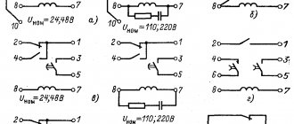
Letter designations in electrical diagrams
The standards for the letter designation of elements on electrical circuits are described in the GOST 2.710-81 standard with the text title “ESKD. Alphanumeric designations in electrical circuits." The mark for automatic devices and RCDs is not indicated here, which is prescribed in clause 2.2.12 of this standard as a designation with multi-letter codes. The following letter codings are accepted for the main elements of electrical panels:
| Name | Designation |
| Automatic switch in the power circuit | QF |
| Automatic switch in the control circuit | SF |
| Automatic switch with differential protection or difavtomat | QFD |
| Switch or load switch | QS |
| RCD (residual current device) | QSD |
| Contactor | K.M. |
| Thermal relay | F, KK |
| Timing relay | KT |
| Voltage relay | KV |
| Impulse relay | KI |
| Photo relay | KL |
| Surge arrester, arrester | F.V. |
| fuse | F.U. |
| Voltage transformer | TV |
| Current transformer | T.A. |
| A frequency converter | UZ |
| Ammeter | PA |
| Wattmeter | PW |
| Frequency meter | PF |
| Voltmeter | PV |
| Active energy meter | P.I. |
| Reactive energy meter | PK |
| Heating element | E.K. |
| Photocell | B.L. |
| Lighting lamp | EL |
| Light bulb or light indicating device | H.L. |
| Plug or socket connector | XS |
| Switch or circuit breaker in control circuits | S.A. |
| Push-button switch in control circuits | S.B. |
| Terminals | XT |
Table 1
| Name | Designation |
| 1. line, track General designation | |
| Note. If it is necessary to distinguish in one diagram the lines being designed from those that are in operation, are subject to dismantling, or have been dismantled, then the following additional designations are used: | |
| 1. Designed line | |
| 2. The line is active | |
| 3. Line to be dismantled | |
| 4. Dismantled line | |
| 2. Crossing lines, routes | |
| Note: If it is necessary to show the relative position in height of intersecting lines or routes, then the line or route located below is depicted with a break at the intersection | |
| 3. Radio relay line |
Letter designations of gear types are given in table. 2.
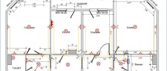
Representation of electrical equipment on plans
Despite the fact that GOST 2.702-2011 and GOST 2.701-2008 take into account this type of electrical circuit as a “layout diagram” for the design of structures and buildings, one must be guided by the standards of GOST 21.210-2014, which indicate “SPDS.
Images on the plans of conventional graphic wiring and electrical equipment.” The document establishes UGO on plans for laying electrical networks of electrical equipment (lamps, switches, sockets, electrical panels, transformers), cable lines, busbars, tires.
The use of these symbols is used to draw up drawings of electric lighting, power electrical equipment, power supply and other plans. The use of these designations is also used in basic single-line diagrams of electrical panels.
Conventional graphic images of electrical equipment, electrical devices and electrical receivers
The contours of all depicted devices, depending on the information richness and complexity of the configuration, are taken in accordance with GOST 2.302 on the scale of the drawing according to the actual dimensions.
Conventional graphic designations of wiring lines and conductors
Conventional graphic images of tires and busbars
IMPORTANT: The design position of the busbar must exactly coincide on the diagram with the place of its attachment.
Conventional graphic images of boxes, cabinets, panels and consoles
Conventional graphic symbols of switches, switches
On the pages of documentation GOST 21.210-2014 there is no separate designation for push-button switches, dimmers (dimmers). In some schemes, according to clause 4.7. the normative act uses arbitrary designations.
Conventional graphic symbols of plug sockets
Conventional graphic symbols of lamps and spotlights
The updated version of GOST contains images of lamps with fluorescent and LED lamps.
Conventional graphic symbols of monitoring and control devices
Graphic designation of SPD
The general view of SPDs for circuits is regulated in GOST R IEC 61643-12-2011 (Read PDF) “Surge protection devices in low-voltage power distribution systems. Principles of selection and application”, according to which the symbol looks like this (see image below):
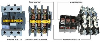
Modern modular surge suppressors installed in electrical panels (ASU, ShchS, etc.), depending on the type, include other additional means of protection.
For example, both voltage and current limiting components are contained in a single package. In such cases, it is permissible to add markings of the corresponding controlled quantities to the standard schematic designation, for example, like this:
Also, often on diagrams where an SPD is used, a graphic designation of the main element on which it is built is shown - Varistor, Arrester or Gas-filled Arrester:
Each of the presented types of protection has its own pros and cons, therefore, information from a single-line diagram about what equipment is installed can be very important. Additionally, this is also indicated by marking the SPD on the diagrams with a letter code.
designation of a three-phase surge protector on the diagram
For three-phase SPDs, it is permissible to use the standard designation presented above, additionally indicating the number of connected conductors.
But there are diagrams in which three-phase SPDs are shown as three separate elements, for example varistors, combined in one housing. Both of these types are correct, but for convenience, simplicity and better readability of the drawing, it is better to use the first option.
Letter marking
There is no separate letter code for surge protection devices . Therefore, on single-line diagrams, it is customary to mark SPDs in accordance with GOST 2-710-81 (READ PDF) “Alphanumeric designations in electrical circuits” with two possible codes, depending on the main component used in a specific SPD model:
FV – on arresters
RU – on varistors
In the image below, an example of the correct designation of UZIP on a single-line diagram of a simple electrical panel:
The diagram shows a device in which, after the introductory two-pole circuit breaker, the neutral and phase conductors are connected, and the third terminal is connected to the protective grounding bus of the electrical panel PE.
OPN device
The nonlinear resistance in an arrester device is a variable resistance (varistor).
Its variability is important when currents change and is visible on the current-voltage characteristic of o-pe-en-a.
Resistors are produced in the form of disks, which consist of metal oxide ceramics. They are connected in series and in parallel inside the insulating housing, depending on the voltage class and capacity of the arrester.
For each arrester, it is important that all resistances have the same current-voltage characteristics. Otherwise, individual resistances will heat up more, which will lead to destruction of the resistances themselves and the entire surge arrester as a whole.
Nonlinear resistances are located inside an insulated housing. Previously, porcelain and ceramics were used for insulation. Currently, you can find surge arresters whose external insulation is made of polymer insulating material.
The external insulation is made of a complex shape, the number and shape of the ribs is determined by the requirement of the leakage path of the external insulation. The creepage distance characteristic itself determines the minimum dimensions of the arrester.
An important characteristic of the insulation condition is the cleanliness of the arrester, so it is important to clean it from dust and dirt, since these factors spoil the strength of the external insulation.
Internal insulation is more powerful and durable than external insulation.
In addition to resistances and insulation, the device includes connection terminals. The limiter is connected between phase and ground.