In view of the high cost of electric motors, the issue of protecting them from damage when normal operation is disrupted is quite acute. Among the most popular violations are overload, loss of one of the phases, and reduction in operating voltage. And all of them are characterized by large operating currents flowing in the windings of an electric machine, which leads to overheating, deterioration of the dielectric properties of the insulation and burnout of the cores if the situation is left to chance. To protect electric motors from overheating, a thermal relay is introduced into the power supply circuit of the electric drive.
Design
The modern electrical equipment market offers a huge selection of thermal relays of different operating principles; as a result, their design will also differ. However, in accordance with clause 3.2. GOST 16308-84 all technical parameters of a particular model must correspond to this type in terms of dimensions, design and circuit diagram of this type. The most common option, due to its ease of implementation and relative cheapness, is an electrothermal relay on a bimetallic plate. The design of which is shown in Figure 1.
Rice. 1. Thermal relay design
As you can see, the mechanism includes:
- heating element - a current-carrying part that passes through itself the operating current of an electric machine;
- bimetallic plate - acts as an active indicator that reacts to excess temperature;
- pusher - performs the functions of a rigid lever that transmits force from a bimetallic plate;
- temperature compensator – allows you to make a correction for the ambient temperature to stabilize the operating current value;
- latch – designed to fix the position of the temperature relay;
- release rod - a moving part of the mechanism designed to move contacts;
- relay contacts – transmit power to the control unit;
- spring - creates a force to move the relay to a stable position.
In practice, there are other types of relays, the design of which will be fundamentally different. This option is given as an example to illustrate the processes and explain the operating principle.
Thermal relays RTL
RTL thermal relays are designed to protect AC motors from overloads, as well as to protect them from phase asymmetry, delayed start-up and rotor jamming. They are used in control systems for lifting mechanisms (elevators, cranes, etc.), fans, pumps, thermal curtains, furnaces, machine tools, lighting, and in automatic transfer transfer systems (ATS).
• Rated voltage – up to 660 V AC. • Rated current – from 25 to 500 A. • Number of poles – three. • RTL relays are mounted directly on PML contactors, or on KRL terminal blocks for mounting with screws or on a DIN rail. • RTL relays are part of PML and PM12 starters.
terms of Use
The relays are designed to operate under conditions of exposure to the following climatic factors: • ambient temperature from -40 to +55°C; • altitude above sea level up to 2000 m. It is allowed to use relays in circuits with a rated voltage of 380 V at an altitude above sea level up to 4300 m, while the ambient temperature should not exceed 28 ° C, the electrical insulation strength is reduced to 2000 V AC ( effective value), and the operating and non-operating currents are reduced by 10%; • the upper value of relative air humidity is not more than 98% at a temperature of 25°C; • environment – non-explosive, not containing gases, liquids and dust in concentrations that interfere with the operation of the relay; • The relays are resistant to the following mechanical factors: • vibration of the relay mounting points in the frequency range 1-100 Hz at an acceleration of 9.8 m/s² (1g); • multiple impacts with an acceleration of 29.4 m/s2 (3g) with an impact duration of 2 – 20 ms. The operating position of the relay in space is on a vertical plane with the non-operation current regulator forward, the cover up. Deviation from the working position is allowed up to 15° in any direction.
Specifications
Relay symbol structure
Thermal overload relay RTL-Х1Х2Х3-Х4-Х5...А-(Х6...А)-УХЛ4 Terminal block KRL-ХХ-УХЛ4 Thermal overload relay - RTL product group - Series X1 - Rated relay current: 1 - up to 25 A, 2 - up to 100 A, 3 - up to 250 A, 4 - up to 510 A X2 - Current setting range (conditionally) X3 - D - relay version with reduced overall dimensions (for a rated current of 36 A) X4 - Relay return method: 1 - manual, 2 – self-reset X5...A - Rated current, A (X6...A) - Current setting range of the relay, A UHL4 - Climatic version according to GOST 15150 KEAZ - Trade mark Terminal block - Product group KRL - Letter designation XX - Rated current and relay type: 1 — 25A RTL-1000; 2D - 36A RTL-2000D; 2 - 100A RTL-2000 UHL4 - Climatic version and placement category according to GOST 15150
An example of recording the designation of a relay for a rated current of 100A with a current setting range of 48 - 65 A, with self-resetting, for installation directly on a PML contactor when ordering it and in the documentation of another product: Thermal overload relay RTL-2059-2-100A-(48-65A ) - UHL4 An example of recording the designation of a relay for a rated current of up to 100 A with a current setting range of 48 - 65 A, with self-reset, for individual installation with a KRL-2 terminal block: Thermal overload relay RTL-2059-2-100A-(48-65A) - UHL4; Terminal block KRL-2-UHL4
Overall and installation dimensions
Scheme for connecting the relay to the load circuit Electrical circuit diagram
Principle of operation
The work is based on the principle of the difference in temperature expansion of different metals, described by the Joule-Lenz law. When a bimetallic plate consisting of two metals with different coefficients of thermal expansion is heated, its geometric deformation will occur. It is this plate that is installed in the thermostat; it reacts when the temperature exceeds the established limit.
To consider the principle of operation of a temperature relay, we will use a three-dimensional model of a real device shown in Figure 2 below:
Rice. 2. Operating principle of the temperature relay
As you can see, a thermal relay connected to the electric motor circuit passes the main load of the electric machine through the current-carrying buses. If we simulate an overload situation, when a current several times higher than the rated current flows through them, the busbars will begin to heat up and the excess heat will transfer to the bimetallic plate connected to each of the phases of the electric motor. When the set temperature is reached, the bimetallic plate will bend and move one of the pushers. The pusher, in turn, will move the latch lever a few millimeters, which will release the spring mechanism and allow the release rod to move.
After this, the contacts of the thermal relay will turn off the power to the control circuit and close the contacts of the alarm circuit, which will notify that the protective device has been disconnected. After eliminating the cause of overheating, the relay returns to its operating position by pressing a mechanical button. It should be noted that immediately after turning off the thermal relay, it will not be possible to turn it on, since the bimetallic plate has not yet cooled down and false alarms are possible. Therefore, the process requires a certain time delay, after which the electric motor can be put into operation.
Designation on the diagram
When reading diagrams, it is important to be aware of the designation of all devices depicted on them. This makes it possible to ensure precise connection in compliance with the basic operating parameters of the electrical installation, selectivity of protection operation and maintain normal power supply mode. The image of a thermal relay in the diagrams is determined by the provisions of two regulatory documents. In accordance with Table 3 of GOST 2.755-87, the contacts of this type of equipment are shown as follows (Figure 3):
Rice. 3. Image of thermal relay contact
At the same time, the temperature relay itself has a designation in accordance with clause 21 of Table 1 of GOST 2.756-76 , which is displayed on the diagram as follows (see Figure 4):
Rice. 4. Sensing part of the electrothermal relay
Knowledge of schematic images of an electrothermal relay will allow you to navigate the circuit diagrams of already operating units. Or independently compose and connect the equipment through a protective device.
Kinds
The modern variety of thermal relays covers a fairly wide range. Therefore, division into types is carried out in accordance with established criteria based on clause 1.1. GOST 16308-84 . Thus, according to the type of operating circuit current, all devices are divided into two large groups: AC and DC relays. Depending on the number of working poles there are:
- single-pole – used for DC motors and other single-phase models;
- two-pole - installed in a three-phase circuit, where control can be carried out only in two phases;
- three-pole - relevant for powerful asynchronous units with a squirrel-cage rotor.
Depending on the type of contacts of the secondary circuits, all thermal appliances are divided into models:
- only with normally open contact;
- only with normally open contact;
- with both make and break contacts;
- with switching;
Depending on the method of returning the thermal relay to its original position, there are options with manual activation or with self-return. The models can also implement the function of transferring from one type of work to another.
There is also a division based on the presence or absence of a device to compensate for the temperature of the surrounding space. And models with the ability to adjust the non-operation current or without such a function.
Thermal relay TRN-10, TRN-25
Two-pole thermal current relays TRN-10, TRN-25 with temperature compensation and currents from 0.5 to 25 A. Two-pole thermal current relays TRN-10 UHL4, TRN-25 UHL4 with temperature compensation, with rated currents of thermal elements from 0.5 up to 25 A are intended mainly for protection against unacceptable overloads of three-phase asynchronous electric motors with a squirrel-cage rotor, operating from a network with a rated voltage of up to 500 V at a frequency of 50-60 Hz.
The relays can be used in DC networks with a rated voltage of up to 440 V. The relays do not protect against short circuits and themselves require such protection.
Terms of Use:
– altitude above sea level up to 1000 m (work is allowed at altitudes up to 2000 m at a rated voltage of no more than 380 V at an ambient temperature of +1 to +40 ° C;
– relative air humidity at a temperature of +20 °C no more than 80% and no more than 50% at a temperature of +40 °C;
– frequency of vibration and fastening points is 25 Hz with an acceleration of no more than 0.7 g.
Relays are produced only in open versions and are not designed for operation in explosive environments, as well as in environments containing significant amounts of dust, aggressive gases and vapors in concentrations that destroy metals and insulation. The relays are installed in places protected from direct contact with water, oil, metal dust, etc., as well as outdoors in enclosures not exposed to solar radiation.
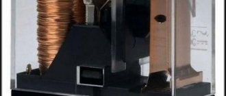
Intermediate relays of the RP21 series are used in control circuits of AC electric drives with voltage up to 240 V - for three- and four-contact relays, with voltage up to 380 V - for one- and two-contact relays, in DC circuits with voltage up to 220 V.
The relay consists of a contact system and an electromagnet. The contact system consists of fixed contacts on flat plates fixed in a plastic base, and movable contacts on flat springs fixed between plastic blocks on the electromagnet armature. The moving contacts are connected to the terminals by flexible connectors. . An electromagnet contains a magnetic circuit, a core, a coil and an armature. The magnetic core is attached to the plastic base with screws. . Soldering lamellas allow the connection of two copper conductors with a total cross-section of 1.5 mm2, screw terminals - two conductors from 0.5 to 1.5 mm2 each.
Purpose
The main purpose of a thermal relay is to protect the electric motor from phase imbalance, overheating during long starts, shaft jamming or excessive load. To solve all these problems, in practice, various types of relays are produced that have a narrow specialization in a specific area; we will consider each of them in more detail below.
- RTL is used to protect three-phase asynchronous electrical machines from the effects of overload currents, overheating due to phase failure or imbalance, and problems with shaft rotation. Can be used either independently or with installation on a PML starter.
- The RTT is designed to work with three-phase units with a squirrel-cage rotor and provides full coverage of emergency modes that lead to overheating of the windings. It can also be installed on a magnetic starter PMA, PME or independently on a mounting panel.
- RTI is a three-phase thermal relay with the possibility of mounting on starters of the KMT, KMI series. They are characterized by stable low power consumption and are switched on together with fuses.
- TRN – used to control the start-up and operating mode of an electric motor; it is little dependent on external temperature factors. It is a two-pole model that can be used to start DC motors.
- Solid-state - unlike the previous ones, it does not have contact groups and moving elements inside. It is used in three-phase circuits where increased fire safety requirements are established.
- RTK - controls temperature indicators not through operating currents, but by placing a sensor in the motor housing. Therefore, the entire interaction process is carried out only by temperature.
- RTE is a kind of fuse, since the shutdown occurs due to the melting of the conductor. The thermal device itself is mounted directly with the electric motor.
Electrothermal relay TRN-25 UHL4
Two-pole electrothermal relays with temperature compensation TRN25 UHL4 are designed to protect electrical installations from overloads in long-term operation. The relays are designed for operation in alternating current networks with a frequency of 50 and 60 Hz with voltages up to 500 V (TRN-10), 660 V (TRN-25 ) and direct current for voltages up to 440 V.
The relays have adjustment of the non-operation current within the range of minus 25 plus 25% of the rated non-operation current.
The failure current is adjusted using the setting regulator. Each division of the regulator scale corresponds to ?5% of the rated non-operation current.
When the regulator is set to position “O”, the rated non-operation current is equal to the rated current of the heater. When the regulator is set to the “+” position, the failure current increases, and when the regulator is set to the “-” position, it decreases in relation to the value of the rated failure current.
When the ambient temperature deviates from plus 20°C, the value of the failure current practically does not change.
When a six-fold non-operation current flows around the relay from a cold state at an ambient temperature of plus 20°C, the relay operates within 6 to 25 s.
The relays are supplied with heaters installed in them, the rated currents of which are specified when ordering. The power consumed by one pole of the TRN-10 relay is 5.4 W, the TRN-25 relay is 6.25 W.
Relays have manual reset only. When the relay is triggered, a return can be made after 2 minutes.
The relays have one break contact, which allows disconnection and long-term flow of the currents indicated in the table. 2 with an inductive load having a power factor of at least 0.3 at an alternating current frequency of 50 and 60 Hz and a time constant of not more than 0.05 s. at constant current.
Thermal relay TRN
Two-pole thermal relays TRN-10, TRN-25 – protect against overloads and phase breaks in circuits with direct voltage up to 400V and alternating voltage up to 660V, rated current load up to 25A and current settings range from 0.37-0.63A to 18- 32A. The operation of the TRN relay is based on the properties of bimetallic elements to change their shape when heated, resulting in a break in the contact circuit. TRN relays are used with PME and PAE starters. Degree of protection – IP00.
Features of the TRP relay.
This type of device is suitable for use under conditions of increased mechanical stress. It has a shock-resistant case and vibration-resistant mechanism. The sensitivity of the automation element does not depend on the ambient temperature, since the response point lies beyond the limit of 200 degrees Celsius. Mainly used with asynchronous motors of three-phase power supply (current limit - 600 amperes and power supply - up to 500 volts) and in DC circuits up to 440 volts. The relay circuit provides a special heating element for transferring heat to the plate, as well as smooth adjustment of the bend of the latter. Due to this, you can change the operating limit of the mechanism up to 5%.
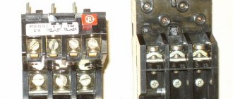
A thermal relay in magnetic starters is installed to protect the electric motor from overloads. The thermal relay consists of four main elements: heater 1, connected in series to a circuit protected from overload; bimetallic plate 2 of two pressed metal plates with different linear expansion coefficients; systems of 3-7 levers and springs; contacts 8 and 9. Thermal relay diagram. 1 - heater; 2 - bimetallic plate; 3 - adjusting screw; 4 - latch; 5 — lever; 6 - spring; 7 — return button; 8 - moving contact; 9 - fixed contact; 10 — heater output
When a current exceeding the rated current of the electric motor passes through the heating element 1, such an amount of heat is released that the loose (in the figure left) end of the bimetallic plate 2 bends towards the metal with a lower linear expansion coefficient (that is, it lowers), presses on the adjusting screw 3 and disengages latch 4. At this moment, under the action of spring 6, the upper end of lever 5 will rise, open contacts 8 and 9 and break the control circuit of the magnetic starter. Button 7 is used to manually return lever 5 to its original position after the relay is activated. From the above it follows that the operation of a thermal relay is based on the bending of a bimetallic plate under the influence of the heat generated in the heating element. But this same plate will also bend under the influence of the heat of the surrounding air. Thus, on hot days the relay will operate faster than on cold days. To eliminate this phenomenon, the relay uses temperature compensation, the essence of which is that the bending of the bimetallic plate due to changes in ambient temperature corresponds to the bending of the compensator plate in the opposite direction. The compensator plate is also a bimetallic plate, but with a deflection opposite to the main bimetallic plate. Thermal relays TRN are built into magnetic starters of the PME-100, PME-200 types and into magnetic starters PAE-300. These relays are two-phase, temperature compensated, with manual reset. The heating of the bimetal is indirect, the heaters are replaceable with a rated current of up to 40 A. The temperature compensator is made of bimetal with a reverse deflection in relation to the main thermoelement. At a steady temperature, a certain gap is established between the compensator and the latch. Changing the size of this gap by turning the eccentric (setpoint adjuster), i.e. Removing or approaching the latch changes the relay setting. Each division of the setpoint regulator corresponds to 5% of the rated current of the heater. When the regulator is set to position “O”, the relay setting current is equal to the rated current of the heater. When the regulator is set to position “-5”, the set current decreases by 25%, when set to position “+5” it increases by 25% in relation to the rated current of the heater. The relay response time at an ambient temperature of 20±5°C and when the relay is heated from a cold state by six times the rated current of the setting at any position of the set control should be within the following limits:
Design of thermal relay TRN-10: 1, 2, 3, 4, 6 - screws; 5 - cover; 7 - heating element; 8 — plastic cover; 9 — rod; 10 - contact bridge
- 3-15 s - for relay TRN-10 A;
- 6—25 s — for relays of types TRN-10; TRN-25 and TRN-40.
The manual reset time of the relay within the ambient temperature range from -40 to +60°C should be no more than 2 minutes. When installing the relay in the operating position at an ambient temperature of 20 ± 5 ° C and a rated current flowing around both poles, the relay should not operate in a steady thermal state and should operate within no more than 20 minutes at a current equal to 1.2 rated current of the setting. The protective characteristics of the relay are shown in Fig. 2.16 and 2.17. Single-phase thermal relays TRP-60 and TRP-150 (Fig. 2.18), built into PAE starters of the fourth, fifth and sixth magnitudes, have combined heating of the bimetallic plate (one part of the current passes through the heating element, the other through the bimetallic plate). With one heater designed for zero set current, it is possible to adjust the set current within ±25%. The relay has a scale with five divisions on either side of zero. The division price is 5% for open execution and 5.5% for protected execution. The TRP thermal relay has two return options: manual return with guaranteed non-self-reset of the contact group and self-reset with manual return acceleration. The relay does not operate when there is a long-term flow of current equal to the set current; triggers within 20 minutes after the current increases by 20% compared to the set current. The relay operates normally at currents not exceeding 15 times the value. The relay allows a load of 18 times the rated current of the thermal element for 1 s, or until the relay operates if it occurs in less than 1 s.
Multiplicity of operating current in relation to the installation current
Protective characteristics of the TRN-25 and TRN-40 relays 1 - zone of protective characteristics when the relay is activated from a cold state; 2 - zone of protective characteristics when the relay is activated from a hot state (after warming up) Multiplicity of the operation current in relation to the installation current
Protective characteristics of the TRN-10A relay 1 - zone of protective characteristics when the relay is activated from a cold state; 2 - zone of protective characteristics when the relay is activated from a hot state (after warming up)
Thermal relays type TRP: 1 - bimetallic plate; 2 — self-return stop; 3 — movable contact holder; 4 - spring; 5 - moving contact; 6 - fixed contact; 7 - replaceable heater; 8 — setting current regulator; 9 - manual return button
To protect the TRP-60 and TRP-150 relays from short circuit currents, it is sufficient that the rated current of the fuse insert connected in series with the thermal element of the protected relay exceeds the rated current of the thermal element by no more than 4-5 times.
Specifications
Correct operation of relay protection is ensured by matching the parameters of the thermal device to the specified operating conditions of the electrical machine. Therefore, it is important to study the basic operating parameters of the relay before purchasing it. The main technical data of the thermal relay include:
- the rated voltage value and frequency for which it is designed;
- time-current characteristic – determines the response time at a set excess factor;
- time for the thermal element to return to its original position;
- setting current change range;
- thermal resistance to exceeding the operating value;
- climatic design and degree of dust and moisture protection.
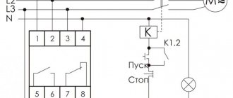
Connection diagrams
The connection of the above models of thermal relays can be made according to several schemes, differing depending on the specific type of equipment. Let's consider the most relevant of them.
Rice. 5. Thermal relay connection diagram
As you can see in Figure 5, three-phase relay RT1 is connected in series to motor M. Power is supplied to them through contactor KM. In normal operation, the RT1 contacts are normally closed and current flows through the KM coil. As soon as an emergency mode occurs, the thermal protection will open the contacts and the contactor coil will be de-energized, powering the motor will be cut off.
A two-pole relay is switched on in a similar way, with the difference that the contacts of the protective device are connected in series only in two phases out of three, as shown in the figure below:
Rice. 6. Connection diagram for a two-pole relay
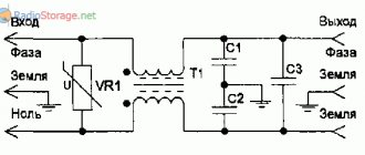
In addition, there is a circuit for switching on a thermal relay for powerful electric motors, the operating current of which is several times higher than the permissible limit for the protective device. In such situations, transformer conversion is used, and the connection diagram looks like this:
Rice. 7. Transformer connection diagram
Questions and answers on electric motors
Question-and-answer session on electric motors for variable-frequency drives. Before the words “Read more,” part of the questions and answers is given.
-I have a regulation range of 1:10, is a regular industrial one
electric motor for operation with a frequency converter?
- Conditionally
suitable.
At frequencies below 25Hz
the electric motor
must
operate
in intermittent mode with duty cycle = 25%
due to the insufficient cooling capacity of the fan. For eight or more pole electric motors, this value can be increased to 30 Hz.
-I have a control range of 1:20. Is a conventional electric motor suitable for operation with a frequency converter?
–Conditionally
suitable. At frequencies
below 25 Hz,
the electric motor must operate in
intermittent mode with duty cycle = 25%
due to insufficient cooling by the electric motor fan.
-I have a control range of 1:50
(and above) is
a conventional
electric motor suitable for operation with a frequency converter?
–No
, not suitable. A special electric motor is required. For example, ADHR. - I need to get 2000 rpm instead of 1400 rpm, how can I do this? Are there any restrictions?
– You can use a frequency converter by setting the upper control limit to 100Hz
and setting the frequency to 66.7 Hz. The torque on the electric motor shaft
may drop
(if you do not use frequency converters with top regulation type
C2000)
. If you have a frequency converter
other than the VFD-C model
, then it is better to choose a more powerful electric motor.
– I have a 400Hz
.How to include it in a regular network?
– 400 Hz
the electric motor is connected to a regular network either through
a machine unit
, or through a frequency converter having an upper operating frequency of at least
400 Hz
(converters with an output frequency of 0-120 Hz are not suitable). In most frequency converters, the voltage at the rated frequency is regulated, but we must remember that The current through the motor should not exceed
120% of the rated current of the frequency converter.
The frequency converter is selected according to
the electric motor current
. - I have a 100Hz electric motor. How to connect it to a regular network? - A 100Hz electric motor is connected to a regular network through a frequency converter. The settings are the same as for a 400Hz electric motor.
-I have a three-phase electric motor of 220 Volts
How to connect it to a
380 Volt
?
– Such an electric motor is connected to a 380 Volt network either through a three-phase transformer or through a frequency converter. If soft starting or frequency adjustment is necessary, only a frequency converter is allowed. The frequency converter is selected according to the rated current of the electric motor.
-I have a three-phase 42 Volt
.
How to connect it to a 380 Volt
? And to a
220 Volt
?
380 Volt network
a 42-volt electric motor can be turned on either through a three-phase transformer, or through a frequency converter that
allows setting the rated voltage below 100 Volts
. In this case, the frequency converter is selected not by power, but by
the current
the electric motor. A 42 volt electric motor can be connected to a 220 Volt network through a frequency converter. The frequency converter is selected in the same way as a 380 Volt frequency converter. - I have an electric motor with a brake. How to connect it to a frequency converter?
– To connect to a frequency converter, you must select
brake power circuit. This circuit is passed either through the contactor or through the relay contacts of the frequency converter.
Criterias of choice
The main criterion when choosing a specific model is that the rated load corresponds to the permissible range of the thermal relay itself. For normal operation of an electric machine, you need to operate at a 20 - 30% overload in no more than a 5 minute interval. The current value is calculated by the formula:
Iwork = 1.2*Inom
This means that the permissible control limit must include the resulting tripping current value. Then, check on the time-current characteristic (see Figure 8) for what period of time the protection will operate at this multiplicity:
Rice. 8. Time-current characteristic
In this case, the time will be equal to 4 minutes at 20% thermal excess, which fully satisfies the criteria of the task.
How to choose a circuit breaker for your engine
The correct selection of a circuit breaker to protect an electric motor is of great importance for the equipment. Reliability of operation, protection of the engine from emergency operating conditions and wiring directly depend on the selection of the circuit breaker.
In this article we will outline the conditions for choosing a circuit breaker to protect an electric motor. In order to choose a circuit breaker you need to know:
— rated motor current;
— multiple of the starting current to the rated current;
— maximum permissible electrical wiring current.
Motor rated current
- this is the current that the electric motor has during operation at rated power. It is indicated on the electric motor passport or taken from the electric motor passport data tables.
Multiplicity of starting current to rated current
– this is the ratio of the starting current that occurs in the electric motor during start-up to the rated current. It is also indicated on the electric motor passport or in the electric motor tables.
Maximum permissible wiring current
- this is the permissible current that can pass through a wire or cable that is connected to an electric motor.
Conditions for correct selection of circuit breaker
to protect the electric motor:
— the rated current of the circuit breaker must be greater than or equal to the rated current of the electric motor. For example: electric motor current AIR112M4U2 In. dv. =11.4A, select the VA51G2534 circuit breaker for rated current In. = 25A and release current IN..ras. = 12.5A.
After this, we will check that the circuit breaker does not trip when starting the electric motor using the following condition:
Iu.e.>kzap. · kр.у · kр.п. ·In.dv ·ki
note
where Kzap . — safety factor that takes into account voltage fluctuations, Kzap. = 1.1;
kр.у - coefficient that takes into account the inaccuracy of the insertion of the operating current of the electromagnetic release of the circuit breaker, Kр.у = 1.2;
kr.p. — coefficient that takes into account the possible deviation of the starting current from its rated current, kр.п. = 1.2;
K i is the catalog multiplicity of the starting current of the electric motor;
In.dv - rated motor current, A.
Iу.е = 14 · In.ros = 14 · 12.5 = 175A
From the table of electric motors we find K i = 7.0 for the AIR112M4U2 electric motor.
We substitute in the condition and determine
175A > 1.1 1.2 1.2 7.0 11.4
175A > 126.4A
The condition is met, therefore the circuit breaker will not trip when the engine starts.
— the rated current of the circuit breaker must be less than the maximum permissible current of the cable that powers the electric motor. For example: the connection is made with an AVRG cable (3x2.5) which has a permissible current Iadd = 27A. For a water circuit breaker to protect the electric motor, the condition is met because Iadd = 27A > Ін. = 25A.
In this article, you learned how to correctly select the correct circuit breaker to protect the electric motor using the selection conditions.
Source: https://camcebemacter.ru/kak-podobrat-avtomaticheskij-vyklyuchatel-dlya-dvigatelya/