In the material we will understand the concept of induced emf in situations of its occurrence. We will also consider inductance as a key parameter for the occurrence of magnetic flux when an electric field appears in a conductor.
Electromagnetic induction is the generation of electric current by magnetic fields that change over time. Thanks to the discoveries of Faraday and Lenz, patterns were formulated into laws, which introduced symmetry into the understanding of electromagnetic flows. Maxwell's theory brought together knowledge about electric current and magnetic fluxes. Thanks to Hertz's discovery, humanity learned about telecommunications.
Magnetic flux
An electromagnetic field appears around a conductor carrying electric current, but in parallel, the opposite phenomenon also occurs - electromagnetic induction. Let's consider magnetic flux using an example: if a frame made of a conductor is placed in an electric field with induction and moved from top to bottom along magnetic lines of force or left and right perpendicular to them, then the magnetic flux passing through the frame will be a constant value.
When the frame rotates around its axis, then after some time the magnetic flux will change by a certain amount. As a result, an induced emf appears in the frame and an electric current appears, which is called induction.
EMF from the law of electromagnetic induction
The magnetic flux through the same circuit as in the example above will be equal to:
Ф = B*S*cos(90-a) = B*S*sin(a).
Here angle (90-a) = angle between the magnetic induction vector and the normal to the contour surface. Over some time ∆t, the contour area will change by ∆S = -l*V*∆t. The minus sign indicates that the area is decreasing. During this time, the magnetic flux will change:
∆Ф = -B*l*V*sin(a).
Then the induced emf is equal to:
Ei = -∆Ф/∆t = B*l*V*sin(a).
If the entire circuit moves inside a uniform magnetic field at a constant speed, then the induced emf will be zero, since there will be no change in the magnetic flux.
- An induced emf will also arise when the frame is rotated inside a magnetic field.
induced emf
Let us understand in detail what the concept of induced emf is. When a conductor is placed in a magnetic field and moves with the intersection of field lines, an electromotive force called induced emf appears in the conductor. It also occurs if the conductor remains stationary, and the magnetic field moves and intersects the conductor with lines of force.
When the conductor where the EMF occurs is closed to the external circuit, due to the presence of this EMF, an induced current begins to flow through the circuit. Electromagnetic induction involves the phenomenon of inducing an EMF in a conductor at the moment it is crossed by magnetic field lines.
Electromagnetic induction is the reverse process of transforming mechanical energy into electric current. This concept and its laws are widely used in electrical engineering; most electric machines are based on this phenomenon.
Sample task
Given:
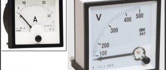
A square-shaped circuit with side d = 0.5 m is “retracted” at a constant speed v = 4 m/s into the region of a uniform magnetic field, the induction value of which is B = 1 T (see Fig. 4). The electrical resistance of the circuit is R = 2 Ohms.
Rice. 4. Example of a problem on electrostatic induction
We need to find answers to the following questions:
a) When (at what moment/s) will electric current flow in the frame?
b) Determine the direction of this electric current.
(c) Calculate the value of the force acting on the frame when it moves in accordance with the direction of the velocity vector. Assume no mechanical resistance to movement.
Solution.
(a) Induction current flows when the flux of magnetic induction changes through the surface covered by the loop. In the situation shown in Figure 4, the magnetic flux is zero and will remain so until the right edge of the loop touches the boundary of the magnetic field region. Then, as the circuit moves, it will be filled more and more with a magnetic field - the magnetic flux will increase. Therefore, the condition of electromagnetic induction is satisfied, i.e. induced current begins to flow. How long? This is easy to calculate since the movement of the frame is uniform:
t = d / v = 0.5 / 2 = 0.25 seconds
The current will flow until the entire square enters the magnetic field. Then the flow will be non-zero, but will no longer change.
b) Let's use Lenz's rule. We have already noticed that the flux of magnetic induction increases when the circuit is “pulled” into a magnetic field. Therefore, the induced current will flow in such a direction as to counteract the increase in flux.
The magnetic field created by the induced current with the induction vector Bind will be opposite to the vector B.
Thus, the vector Bind is directed in our direction. If you position the right thumb in this way, the remaining bent fingers will show the direction of the induction current. The current will flow counterclockwise.
(c) Let us again use the uniformity of movement of the frame. Note that the force that acts on the frame as it moves along the velocity vector (for example, the force of my hand) cannot be the only force acting on the square. If that were the case, he would be moving faster. Since the movement is uniform, this means that at each moment there is a force that balances the force of my hand. This is electrodynamic force. After all, now a current flows in the frame, and part of it flows in a magnetic field (see Fig. 5).
Rice. 5
The red arrow shows the direction of the electric current. The electrodynamic force (Ampere force) acts from the left (I defined it using the three-finger rule). Electrodynamic forces also act on the upper part of the frame and the lower part, but they cancel each other.
To summarize: the electrodynamic force balances the force of my hand. So I can compare the values of both the forces i.e. F = Fed = B * I * d where I is the strength of the induced current. Now it is enough to calculate the strength of this current. We will use Faraday's law and Ohm's law for the circuit section. Let's start with the latter: since we are only interested in the value of I, we write
I = εind / R.
| εind | = ΔФB / Δt = Δx * d * B / Δt = ( Δx / Δt ) * d * B = v * d * B .
After substitution into I we get: I = εind / R = v * d * B / R .
Ultimately, the desired value of the force will be expressed through: Fed = B * I * d = (B * d * v * d * B) / R = (B2 * d2 * v) / R.
Substituting the numerical values we get: Fed = F = (12 * 0.52 * 4) / 2 = 0.5 N.
Movement of a wire in a magnetic field
The value of the induced emf is determined depending on the length of the conductor crossed by the field lines. With a larger number of power lines, the magnitude of the induced emf increases. As the magnetic field and induction increase, a greater value of EMF occurs in the conductor. Thus, the value of the induced emf in a conductor moving in a magnetic field is directly dependent on the induction of the magnetic field, the length of the conductor and the speed of its movement.
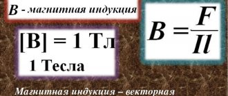
This dependence is reflected in the formula E = Blv, where E is the induced emf; B is the value of magnetic induction; I is the length of the conductor; v is the speed of its movement.
Note that in a conductor that moves in a magnetic field, induced emf appears only when it crosses the magnetic field lines. If the conductor moves along the lines of force, then no emf is induced. For this reason, the formula applies only in cases where the movement of the conductor is directed perpendicular to the lines of force.
1.20. Electromagnetic induction. Lenz's rule
The phenomenon of electromagnetic induction was discovered by the outstanding English physicist M. Faraday in 1831. It consists in the occurrence of an electric current in a closed conducting circuit when the magnetic flux penetrating the circuit changes over time.
The magnetic flux Φ through the area S of the circuit is the quantity
| Φ = B S cos α, |
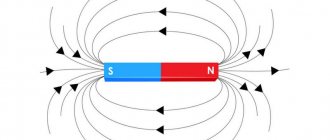
where B is the magnitude of the magnetic induction vector, α is the angle between the vector and the normal to the contour plane (Fig. 1.20.1).
| Figure 1.20.1. Magnetic flux through a closed loop. The normal direction and the selected positive direction of the contour traversal are related by the right gimlet rule |
The definition of magnetic flux is easy to generalize to the case of a non-uniform magnetic field and a non-planar circuit. The SI unit of magnetic flux is called the weber (Wb). A magnetic flux equal to 1 Wb is created by a magnetic field with an induction of 1 T, penetrating in the normal direction a flat contour with an area of 1 m2:
| 1 Wb = 1 T · 1 m2. |
Faraday experimentally established that when the magnetic flux changes in a conducting circuit, an induced emf ind arises, equal to the rate of change of the magnetic flux through the surface bounded by the circuit, taken with a minus sign:
This formula is called Faraday's law.
Experience shows that the induction current excited in a closed loop when the magnetic flux changes is always directed in such a way that the magnetic field it creates prevents the change in the magnetic flux that causes the induction current. This statement, formulated in 1833, is called Lenz's rule.
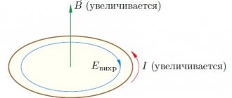
Rice. 1.20.2 illustrates Lenz’s rule using the example of a stationary conducting circuit that is in a uniform magnetic field, the induction modulus of which increases with time.
| Figure 1.20.2. Illustration of Lenz's rule. In this example, a ind < 0. The induction current Iin flows towards the selected positive direction of bypassing the circuit |
Lenz's rule reflects the experimental fact that ind and always have opposite signs (the minus sign in Faraday's formula). Lenz's rule has a deep physical meaning - it expresses the law of conservation of energy.
A change in the magnetic flux penetrating a closed circuit can occur for two reasons.
1. The magnetic flux changes due to the movement of the circuit or its parts in a time-constant magnetic field. This is the case when conductors, and with them free charge carriers, move in a magnetic field. The occurrence of induced emf is explained by the action of the Lorentz force on free charges in moving conductors. The Lorentz force plays the role of an external force in this case.
Let us consider, as an example, the occurrence of an induced emf in a rectangular circuit placed in a uniform magnetic field perpendicular to the plane of the circuit. Let one of the sides of a contour of length l slide with speed along the other two sides (Fig. 1.20.3).
| Figure 1.20.3. The occurrence of induced emf in a moving conductor. The component of the Lorentz force acting on a free electron is indicated |
The Lorentz force acts on the free charges in this section of the circuit. One of the components of this force, associated with the transfer speed of charges, is directed along the conductor. This component is shown in Fig. 1.20.3. She plays the role of an outside force. Its module is equal
| FL = eυB |
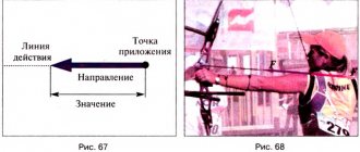
The work done by the force FL on the path l is equal to
| A = FL · l = eυBl. |
According to the definition of EMF
In other stationary parts of the circuit, the external force is zero. The ratio for ind can be given the usual form. During time Δt, the contour area changes by ΔS = lυΔt. The change in magnetic flux during this time is equal to ΔΦ = BlυΔt. Hence,
In order to establish the sign in the formula connecting ind and it is necessary to select the normal direction and the positive direction of traversing the contour that are consistent with each other according to the right gimlet rule, as is done in Fig. 1.20.1 and 1.20.2. If this is done, then it is easy to arrive at Faraday's formula.
If the resistance of the entire circuit is equal to R, then an induction current equal to Iind = ind/R will flow through it. During the time Δt, Joule heat will be released at the resistance R
The question arises: where does this energy come from, since the Lorentz force does no work! This paradox arose because we took into account the work of only one component of the Lorentz force. When an induction current flows through a conductor located in a magnetic field, another component of the Lorentz force, associated with the relative speed of movement of the charges along the conductor, acts on the free charges. This component is responsible for the appearance of the Ampere force. For the case shown in Fig. 1.20.3, the ampere force modulus is equal to FA = IB l. Ampere's force is directed towards the movement of the conductor; therefore it does negative mechanical work. During time Δt this work Amech is equal to
A conductor moving in a magnetic field through which an induced current flows experiences magnetic braking. The total work done by the Lorentz force is zero. Joule heat in the circuit is released either due to the work of an external force, which maintains the speed of the conductor unchanged, or due to a decrease in the kinetic energy of the conductor.
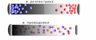
2. The second reason for the change in the magnetic flux penetrating the circuit is the change in time of the magnetic field when the circuit is stationary. In this case, the occurrence of induced emf can no longer be explained by the action of the Lorentz force. Electrons in a stationary conductor can only be driven by an electric field. This electric field is generated by a time-varying magnetic field. The work done by this field when moving a single positive charge along a closed circuit is equal to the induced emf in a stationary conductor. Therefore, the electric field generated by a changing magnetic field is not potential. It is called the vortex electric field. The concept of a vortex electric field was introduced into physics by the great English physicist J. Maxwell in 1861.
The phenomenon of electromagnetic induction in stationary conductors, which occurs when the surrounding magnetic field changes, is also described by Faraday's formula. Thus, the phenomena of induction in moving and stationary conductors proceed in the same way, but the physical cause of the occurrence of induced current turns out to be different in these two cases: in the case of moving conductors, the induction emf is due to the Lorentz force; in the case of stationary conductors, the induced emf is a consequence of the action on free charges of the vortex electric field that occurs when the magnetic field changes.
| Model. Electromagnetic induction |
| Model. Faraday's experiments |
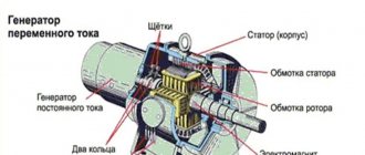
| Model. Alternator |
Rotating reel
The operation of an electric current generator is based on the rotation of a coil in a magnetic flux, where there is a certain number of turns. EMF is induced in an electric circuit whenever a magnetic flux crosses it, based on the magnetic flux formula Ф = B x S x cos α (magnetic induction multiplied by the surface area through which the magnetic flux passes and the cosine of the angle formed by the direction vector and perpendicular to the plane lines).
According to the formula, F is affected by changes in situations:
- when the magnetic flux changes, the direction vector changes;
- the area enclosed in the contour changes;
- the angle changes.
It is allowed to induce an EMF with a stationary magnet or a constant current, but simply by rotating the coil around its axis within the magnetic field. In this case, the magnetic flux changes when the angle value changes. During rotation, the coil crosses the magnetic flux lines, resulting in an emf. With uniform rotation, a periodic change in the magnetic flux occurs. Also, the number of field lines that intersect every second becomes equal to the values at equal time intervals.
In practice, in alternating current generators, the coil remains stationary, and the electromagnet rotates around it.
Where are different types of EMF used?
The movement of a conductor in a magnetic field is used to generate electricity. The rotation of the rotor is ensured by the difference in liquid levels (hydroelectric power station), wind energy, tides, and fuel engines.
Transformer operating principle
Different numbers of turns (mutual inductance) are used to change the voltage in the secondary winding of the transformer as desired. In such designs, mutual coupling is increased using a ferromagnetic core. Magnetic induction is used to generate a powerful repulsive force when creating ultra-modern transport highways. The created levitation makes it possible to eliminate the force of friction and significantly increase the speed of the train.
Self-induced emf
When an alternating electric current passes through the coil, an alternating magnetic field is generated, which is characterized by a changing magnetic flux that induces an emf. This phenomenon is called self-induction.
Due to the fact that the magnetic flux is proportional to the intensity of the electric current, then the formula for the self-induction emf looks like this:
Ф = L x I, where L is inductance, which is measured in H. Its value is determined by the number of turns per unit length and the size of their cross section.
Mutual induction
If you assemble a module from two coils, under certain conditions you can observe the phenomenon of mutual induction. A basic measurement will show that as the distance between elements increases, the magnetic flux decreases. The opposite phenomenon is observed as the gap decreases.
To find suitable components when creating electrical circuits, you need to study thematic calculations:
- you can take as an example coils with different numbers of turns (n1 and n2);
- mutual inductance ( M I passes through the first circuit will be calculated as follows:
M2 = (n2 * F)/ I1
- after transforming this expression, determine the value of the magnetic flux:
F = (M2/ n2) *I1
- To calculate the emf of electromagnetic induction, the formula is suitable from the description of the basic principles:
E2 = — n2 * ΔF/ Δt = M 2 * ΔI1/ Δt
If necessary, you can use a similar algorithm to find the ratio for the first coil:
E1 = - n1 * ΔF/ Δt = M 1 * ΔI2/ Δt.
It should be noted that in this case it is the force (I2) in the second operating circuit that matters.
The joint influence (mutual induction - M) is calculated using the formula:
M = K * √(L1 * l2).
A special coefficient (K) takes into account the actual coupling force between the coils.