It is better if the rated operating current of the circuit breaker is one step lower than that of the RCD. Why do you need a switchboard? Several systems can be called an electrical switchboard. Xn - connection terminals.
They are especially often installed outdoors. How to assemble a single-phase metering panel.
Photo tips for assembling the panel Installation and assembly of the electrical panel The electrical panel includes complex modular equipment.
Such decisions may affect the safety of the residents of the house in which electricity is installed. In terms of strength and IP protection, they are not inferior to metal ones. Only high-quality components of the electrical panel can ensure electrical safety.
All storage water heating devices, washing machines and electric stoves must be connected to the panel with an electrical cable of 2.5 sq.
Switchboard in an apartment with a three-phase electric stove. In some houses, a three-phase network cable comes into the apartment, but the Volt voltage is used only to connect the electric stove. Each manufacturer offers shields with different configurations.
Single line diagrams
Installation and assembly of electrical panel
The electrical panel includes complex modular equipment. If necessary, you can carry out the installation yourself, but first you need to learn how to properly assemble the shield.
To separate the work of electrical components and housing installation, you should purchase a panel that has a removable frame and DIN rails.
There are several types of electrical panel installation:
- wall mounting;
- installation in the wall.
Let's consider the second option, since the first one is installed simply on holders. Before you hollow out an opening in the wall, you need to make sure that it is not “load-bearing” in the house. According to the rules, installation work cannot be done in it.
It is recommended to install electrical panels near the front door. This is a corridor or hallway with good lighting and normal air humidity.
The electrical panel must be visible. Doors should not impede his access. For safety reasons, the shield should not be placed near gas pipes or other flammable substances. To place it on the wall, it is necessary to take into account the height from the floor to its lower edge of at least 1.4 m, and the distance of the upper edge from the floor is no more than 1.8 m.
A building level will help mark out the future area. To maintain all dimensions, you can attach the body to the wall and outline it with chalk. A slot is made using a grinder along the marked lines.
A chisel and a hammer drill will help to hollow out the inside. You need to check the depth of the resulting niche by inserting the electrical panel housing into it.
First, the mount included in the kit is mounted there. Then the electrical panel. For fastenings, holes are made and dowels are inserted. The remaining cavities are sealed with polyurethane foam.
DIN rails are unscrewed from the electrical panel in order to install modular equipment on them. If the kit does not include special fasteners, then you need to drill holes in the back wall of the shield for future fastenings. This is done carefully; excessive force may cause the housing to burst.
Protection of the insides of the electrical panel from repair and finishing work
The internal filling of the switchboard is the most expensive part of the device, so it is important to protect it from construction dust and other contaminants.
To do this you should:
- Insulate all cable ends with electrical tape or caps from felt-tip pens, pens, etc.
- Frames, doors, and other external movable parts of the body are removed.
- The cables are neatly laid inside the shield, counterclockwise or clockwise, from left to right and without sharp bends.
- The box is closed with a special lid or one made independently from cardboard, and the perimeter of the joint with the wall is covered with masking tape.
How to insert cables correctly
An electrical panel with a removable cover will help you insert the wires inside correctly and conveniently. Conventional enclosures have holes for cables that are slightly cut or pressed out. They are located at the top or bottom of the body. They may also be in its back wall.
In electrical panels of low quality, there may not even be a hint of any holes. Then you will have to mark and drill them yourself; not everyone has the patience for this. Therefore, it is better to buy a housing that is more expensive and will take less time to install.
Modern housings for core planting have plugs. They are removed after the shield is installed in the wall. Cables are inserted into the resulting holes. Instead of plugs there may be stuffing box plates.
The first step is to start the input core. It should be located near the input machine. There are comb-type fastenings on the shield; the lead-in conductor should be attached to it. A plastic clamp is used as a tie. Its excess ends are cut off.
The cable is marked with markings, which are indicated on the diagram. This is done with all veins. After their installation, a removable cover is applied and marks are made on it. Cutouts are made along them, and the lid falls into place.
- SIP wires: types, differences from cable, features and advantages
- What is a Power Cable?
- How to conveniently unwind a cable coil on site during electrical installation
Danger of zero loss
By three-phase input. It is very important to control the places that I marked in the diagram. There, a break in the “three-phase” zero is possible; this accident will lead to equipment breakdowns. Recently there was such a case, the owner flew in for many thousands.
These places are marked with a red cross:
Diagram indicating dangerous places where a zero break is possible
On zero loss, if you are interested, I have several articles, for example this one.
How to cut cables inside a switchboard
The insulation must be removed from the inserted cores. This process is done carefully; conductive wires must not be damaged. Immediately a second mark is made on it. This is important because there can be a lot of confusion after cutting all the wires.
Paper tape is suitable for labels. Do not forget the main rule: marks must be applied as indicated on the diagram.
In order for the cable to be sufficient for the entire length of the wiring, you need to insert it into the electrical panel and run it to its entire height. Then measure the same distance in height again. The result will be a length twice the height of the shield. This supply of cable will allow you to confidently guide it to the desired point according to all wiring rules, and excess pieces can always be cut off.
Diagram of the old electrical panel (Option 1)
Hello!
I would like to ask for your help and give me some of your time.
The house I bought is relatively old, and the saddest thing is that when it was built, the selection of specialists was terrible. The electrical supply diagram of the two-story house was depressing.
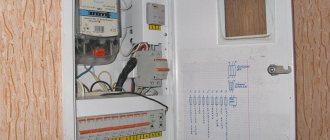
Old shield diagram, simplest (option 1)
Diagram of an old switchboard in a house:
Diagram of an old switchboard in a house
Everything is terribly sad and budgetary. But what’s most depressing is not the fact that the upper “bus” is assembled from exposed pieces of wire. And the fact that such shields in rural areas (like Taganrog, not to mention Varenovka) are considered quite normal. Well, after two traffic jams, switching to automatic machines is chic!
Unfortunately, there is no photo left of the entrance panel, but it was also assembled anyhow.
Assembly of modular panel elements
For those who have never come into contact with such a task, you can provide instructions for assembling an electrical panel. We prepare the workplace; nothing should interfere with the assembly of the modules. We make good lighting.
The following modules will be required:
- circuit breaker (load switch);
- voltage relay;
- residual current device (RCD);
- differential automatic machines;
- circuit breakers;
- cross module.
You can assemble a single-phase panel with your own hands, provided that you have some knowledge of an electrician.
- Wire connector: instructions on how to make the connection yourself. Instructions for use of clamp, clamp and lugs
- Wire lugs: instructions on how to select and install a lug. Overview of all types, photos, instructions, diagrams
Heat shrink for wires: all types and characteristics. Detailed description of how to choose and use heat shrink
All modules are mounted on a previously removed DIN rail. They are arranged in the same order strictly according to the list. The modules are secured using special clamps. Having checked the correct distribution, we proceed to the terminals. You need to loosen the screws on them.
You will need different types of combs. Input clamps (terminals) will help you more conveniently connect the combs to the power wires. They must be placed between the terminal of the module and the comb.
The input load switch has a phase output (lower contact) from which a phase is distributed to the RCD, circuit breakers and other switches. The RCD has zero terminals; they receive a working zero, which is taken from the lower output terminal of the input circuit breaker.
For further assembly of the electrical panel, one end of the neutral wire must be free. It is connected to the main bus of the working zero. Zero buses and zero outputs of all RCDs are switched with a blue wire.
All unused connections are tightened with a screwdriver. After this, the entire installation is checked. After applying voltage to the input circuit breaker, press the test button.
Circuit breaker terminals are checked for voltage. When they are turned on, the same measurements are taken at the output. To prevent household appliances from burning out due to voltage surges, a voltage control relay is installed. The method for assembling a three-phase panel is the same as for a single-phase one. They differ only in the number of conductive wires.
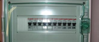
Scheme of a panel with an RCD for individual groups
Electrical panel diagram with RCD for individual groups
The RCD device is triggered at a load from 1 A to 80 mA, which prevents electric shock and death in cases of leakage. The device is suitable for residential premises where the electrical wiring has a total length of 400 m.
You can disable the apartment as follows:
- Installation of the device at the input. An RCD with a response limit of up to 30 mA is suitable for an apartment with a single-phase load of 11 kW.
- Protection against current leakage is also installed on the outlet lines and the split system group.
- One device is located on an integrated system, where each group has a circuit breaker.
- Installation of a standard circuit breaker with metal housings for lighting fixtures.
Each RCD must be placed on a separate bus.
Final installation
When all modular devices have been adjusted and tested, all that remains is to transfer them to the electrical panel housing. For safety, turn off the power. A niche in the wall is being prepared. The assembled devices are mounted on a DIN frame inside the housing.
The main and protective zero buses are mounted. When distributing wires among bundles, it is not recommended to allow them to intersect. The protective zero wires are attached to the PE bus. The connection sequence is observed as in the electrical panel diagram. The protective zero before commutation with the bus terminal is marked.
When all devices are connected, a check begins for compliance with the connection diagram. On the Internet you can see a photo of the assembled electrical panel.
To check the assembled electrical panel, you need to install all switches and sockets in the apartment. Connect the load to sockets on all lines of powerful consumers. After applying voltage, phases and zeros are checked for compliance.
When the adjustment is completed, do not rush to close the electrical panel. It should work for a couple of hours, and then it will become clear whether the assembly was carried out efficiently. Installing and connecting the shield is a labor-intensive process that requires certain knowledge and experience. You should start by studying the theoretical part and follow the step-by-step assembly instructions.
Switching zero. Option 5
In general, when switching the generator and the street, I recommend switching not only the phase wires, but also the neutral wires. But in this case, this is a double-edged sword - if during switching the zero does not make good contact, then there will be a classic zero break.
Recently, a person’s equipment burned down, including a TV worth 100 thousand. The reason was a bad transfer switch, which had a bad zero connection

Zero switching is necessary for safety purposes, to protect personnel working on a de-energized line. And to ensure reliable switching, you need to use reliable components. Namely -
- ABB OT40F3C Reversing switch, 3-pole up to 40A 1SCA104913R1001
- ABB OTPS40FPN1 Additional 40A power pole for switches OT16…OT40F3 (mounting on the left)
- ABB OTPS40FPN2 Additional 40A power pole for switches OT16…OT40F3 (right mounting)
Additional poles are just for zero switching.
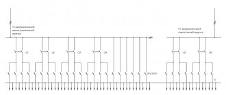
Then the final scheme will be like this:
Panel diagram with zero switching from power sources
Photo tips for assembling the shield
1+
Read here! Wire cross-section: determination by marking and cable diameter. 110 photos and calculation of the optimal option
Download files for the article
• Load distribution / All loads are fully described and divided into phases, xlsx, 15.89 kB, downloaded: 869 times. / • Schemes in Plan / Schemes in Plan - all three options, zip, 58.44 kB, downloaded: 961 times. / • Scheme , option 5 / With zero switching, zip, 82.12 kB, downloaded: 841 times. /
• Expanded Splan libraries / Including elements with thick lines, modular equipment of 2D and 3D photo quality, GOST designations, etc., zip, 32.59 MB, downloaded : 3208 times/ – thanks for sending the libraries to Anton, thanks to whose questions this article appeared!
If there is no Plan, you can have one.
Types of electrical circuit/scheme by method of composition
There are also fundamental standards regarding how to configure a wiring diagram (derived from a well-known school physics course):
- if the components of the wiring diagram are sequentially interconnected, each must be in good working order - the failure of any element entails the breakdown of subsequent ones;
— parallel connection of components to the underlying electrical network does not imply the connection of these elements to each other;
- only a special combined chain (mixed type) involves sections with the appropriate type of connection of segments.
Connecting heating elements star - triangle. Areas of application :: Elemag
Different types of tubular electric heaters (TEHs) can be connected to single-phase and three-phase networks. The electric heater can be connected to a three-phase network using one of two main schemes - “star” or “delta”. To distribute the load evenly in each phase, the number of heating elements must be a multiple of three.
For three-phase networks, heaters are used whose operating voltage is rated at 220 and 380 Volts.
Electrical appliances with an operating voltage of 220 Volts are connected according to the “star” circuit, and heaters with a voltage of 380 Volts are connected to the network according to the “star” and “delta” circuits.
Star connections.
For example, let’s imagine a “star” circuit, which is made up of three electric heaters.
The second output (2) of each of the heaters is supplied with the corresponding phase. The first terminals (1) of the heating elements are connected together with the simultaneous formation of a common point, which is called zero or neutral. This type of load connection is a three-wire one.
It is advisable to use a three-wire connection at an operating voltage of 380 Volts. Below we propose to consider the installation diagram of a three-wire connection of heating elements into a three-phase electrical network. In this case, the supply and shutdown of voltage occurs thanks to three-pole circuit breakers.
In the presented diagram it can be seen that the terminals located on the right side of the electric heaters are connected to phases A, B and C, and the terminals located on the left are connected at the zero point. Between the terminals on the right and the zero point, the operating voltage is 220 Volts.
In addition to the described circuit, you can also use a four-wire one. When connecting using a four-wire circuit, it is assumed that a three-phase load with a voltage of 220 Volts is connected to the network. In this case, the inclusion of the zero point of the load is connected to the zero point of the power source.
In the diagram presented above, the right terminals of the tubular electric heaters are connected to the corresponding phases, and the left ones are closed at one point, which is connected to the zero bus of the power source. Between the zero point and the terminals of the electric heaters, the voltage will be 220 Volts.
If it is necessary to completely disconnect the load from the mains, automatic switches “3+N” or “3P+N” are used. Such machines turn on and off all available power contacts.
Laws that apply when connecting star-type heaters:
Between each phase and zero, the voltage will always be 220 Volts.
To each branch of the “star” you can connect several heating devices, which will be connected to each other in series or parallel order.
The total power of the connection is calculated from the sum of the powers of the three branches
The power of each individual branch must be the same as that of the other branches.
Delta connection
With a delta connection, the leads of the electric heaters are connected to each other in series order. According to the connection diagram of three tubular electric heaters, the connection is carried out in the following order: the first terminal of the heater No. 1 is connected to the first terminal of the heating element No. 2; the second terminal of device No. 2 is connected to the second terminal of device No. 3; the second terminal of heater No. 1 is connected to the first terminal of device No. 3. As a result of this connection, you should get three arms - “a”, “b”, “c”.
Then the corresponding phase is supplied to each arm: to arm “a” phase A, to arm “b” phase B, and to arm “c” phase C.
Laws that apply when connecting heaters of the “triangle” type:
Between any two phases the voltage is always 380 Volts.
Several tubular heaters can be connected to each branch, which will be connected to each other in series or parallel order.
The power of each branch must have the same values.
The total total power is the sum of the power indicators of all three branches.
The voltage in all diagrams is indicated when connected to a three-phase network with a voltage of 380 Volts.
The Elemag company has extensive experience in the production of heating systems. For any questions regarding the purchase or connection of electric heaters, please contact us by phone or email. Our specialists can advise you on choosing the appropriate connection for heating elements. We use STAR and TRIANGLE connections in the production of dry heating elements and traditional electric metal block heating elements.
Security measures
Wiring the electrical panel must be done only by disconnecting it from the power supply. Installation is carried out according to the drawn up diagram; deviation from it, with a high degree of probability, will cause a short circuit.
It is imperative to observe the polarity of the wires; cable marking greatly simplifies this task:
- The black wire corresponds to the phase;
- blue – zero;
- yellow-green – grounding.
Without RCDs it is impossible to provide the required level of protection, so installing them is mandatory.
By adhering to the safety measures listed above and knowing how to connect the circuit breaker in the panel, you will be able to carry out any electrical wiring upgrade in your home.
Choice
Criteria for selecting circuit breakers:
- Rated current. Exceeding it will trigger the overload protection. You can select the correct current based on the cross-section of the wiring into which the machine is embedded. First, the permissible maximum current of the wires is found, and the nominal current for the machine is taken 10-15% lower, then leading to the standard series. The coil hums when the load is exceeded. This can be checked by reducing it. If the current is normal and the machine is humming, there is no danger.
- Operation current. The operating current rating is selected depending on the load. For electronics, a switching class of type A or Z is selected, for lighting - B, for a heating boiler - C, and a powerful electric motor of a machine with a high starting current - D. In this case, all electrical equipment is reliably protected, and the machines will not operate due to the engine starting or operation of the welding machine.
- Selectivity. The current ratings of the circuit breakers are selected depending on the load of each line. The main input should not exceed the maximum permissible total load on the input cable. Based on the rated current, devices are selected primarily as follows: main switch - 40 A, electric stove - 32 A, powerful electrical appliances - 25 A, lighting - 10 A, sockets - 16 A. The general approach is shown here, but the diagram may differ. If an electrical appliance requires 25 A, and the connection is made through a socket, then it must be selected for the same power.
Scheme for connecting machines to the wiring of a typical apartment
The figure above shows a common diagram for connecting automatic machines in a typical apartment. A main two-pole input is installed in front of the meter, then a fire protection RCD is connected (from left to right), and behind it wiring is made to consumers with single-pole circuit breakers. Red indicates phase, blue indicates zero, and brown indicates grounding. The neutral wire and ground buses are connected separately.
On single-pole circuit breakers, it is imperative to connect the phase wire, not the neutral.
- Number of poles. For the main three-phase input, a machine with four poles is selected, and for a single-phase network, with two. Single-pole switches are suitable for household appliances and lighting, and for a three-phase electric motor or electric boiler you will need a three-pole circuit breaker.
- Manufacturer. Since the use of a circuit breaker is related to safety, you should choose products from well-known companies. The stated parameters are not always the same in reality. You should buy devices in specialized stores where they have documentation. Leading manufacturers do not sell bad products. Even counterfeits of such devices can be of normal quality.
Automatic machines with different numbers of poles
The devices are designed for a certain number of operations. It is not recommended to use them as load switches. The mechanism quickly wears out and the contacts burn out. According to the rules, load switching is done using relays or contactors (magnetic starters).
It is important to choose the right number of machines. Usually an input machine is installed, and then to the wiring for sockets, lighting lines and separately for each powerful consumer (if it does not have its own built-in protection). From different manufacturers, machines differ from each other in the methods of fastening and connecting conductors
Therefore, it is recommended to replace the devices with ones similar to those in the panel
From different manufacturers, machines differ from each other in the methods of fastening and connecting conductors. Therefore, it is recommended to replace the devices with ones similar to those in the panel.
Consumer calculations
A complete list of consumers is compiled. To do this, you do not need to take into account devices like a fan or a table lamp, but write down and number each wire connected to the panel. Sockets must be recorded separately, lighting - separately. High-power appliances (boilers, washing machines, air conditioners, electric stoves) require wiring protection from overload, so they are connected not through distribution boxes, but directly to the panel.
The list of consumers for a three-room apartment usually looks like this:
sockets:
- bedroom;
- living room;
- children's;
- kitchen;
- bathroom;
- entrance hall and corridor.
- Washing machine;
- boiler;
- air conditioner;
- electric stove;
- lighting:
- bedroom;
- living room;
- children's;
- kitchen, bathroom;
- hallway, corridor.
All consumers are divided into groups (circuits) in accordance with power consumption: sockets for household appliances in one room such as an iron, sconce, TV and others can be combined into one group (sockets in one room - one group, in another - another), lighting - to the next one, also by room. Each group has its own circuit breaker (or just a circuit breaker) on the panel, and for high-power appliances - washing machine, boiler, electric stove, air conditioner - there is one separately for each. Machines may also be called fuses or bags.
Next, the list is converted into a table where the ratings of the machines and RCDs are entered.