What is a stand-alone inverter
In power supply technology, an inverter is a device that provides a transition from direct voltage to alternating voltage.
As one of the functional modules, it is included in the list of required solar battery units and allows you to obtain standard single-phase or three-phase network voltage from direct current.
Depending on the design features, the applied switching circuit and the list of tasks to be solved, the inverter can have different designs, which is reflected in schematic form in the classification of the figure.
Figure 1. Hierarchy of inverters
The device can be considered as an uninterruptible power supply with expanded functionality.
At the same time, it differs from conventional entry-level UPS primarily in the following main features:
- contains several equal inputs for connecting various sources of electrical energy to them;
- independently controls sources of electricity, providing voltage and frequency of the power network regulated by standards throughout the entire range of permitted loads;
- provides complete isolation of the external electrical input from the intra-house network, for which the functions of the source of electrical energy, regardless of the operating mode, are always taken over by the inverter.
The latter feature determined the generally accepted designation of this device as an autonomous inverter.
Modified and pure sine inverters
The shape of the output voltage graph after converting DC to AC depends on whether frequency filters were used after pulse-width modulation, performed by reconnecting thyristors. The simplest devices produce a so-called “modified sine” output. This is alternating current, the voltage fluctuations of which are displayed on the graph in the form of rectangles.
The only advantage of inverters with a modified sine wave is their low cost. There are loads for which the current they create is quite suitable (electric drills, cutters, even computers), but in many cases such a simple transformation is unacceptable. In some cases, appliances connected to a modified sine wave inverter do not even turn on. And devices such as refrigerators, microwaves, AC motors or pumps will not work efficiently.
Thus, “pure sine” inverters, in which the output current is pre-frequency filtered, are preferable. These devices, for example, make it possible to create uninterrupted power supply for a gas boiler and for many other types of equipment.
Where is it used and how is it turned on?
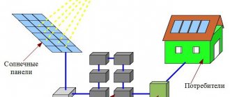
In relation to solar energy, an autonomous inverter, as a device that primarily performs the functions of selecting one of the possible sources of power supply, is installed between the output of the solar battery and the input panel.
The installation location is dictated by simple considerations: the electricity consumer should not know from which source he receives electricity at a given specific point in time, and the required quality of this energy, incl. at the moment of switching between sources, is determined by the choice of appropriate circuit solutions and the element base used.
For reasons of ensuring maximum operational flexibility of intra-house wiring, the external input connection can also be physically made to the house input panel, which is separately highlighted in Figure 2.
Figure 2. Scheme of interaction between the external network, autonomous inverter, input panel and consumers in normal operation
At the same time, this input is equipped with all the necessary accessories and circuit breakers for protection against short circuits, excessively high leakage currents and the like.
The strength of this approach is that it allows, if necessary, without problems, by simply reconnecting just a few terminals, to switch to a standard power supply circuit in which there are no alternative sources.
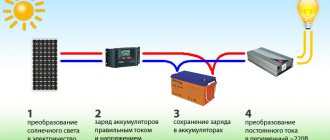
Use of inverters in solar energy
Conventional power plants initially generate alternating current; it then only needs to be synchronized for transmission over a distance. However, solar panels (also called batteries) operate in a completely different way. They create high voltage direct current (200 to 600 volts). It cannot be used in this form. Special controllers are used that reduce the voltage. These devices can be separate devices, or part of the inverter. In the second case, the installation diagram of the solar power plant is somewhat simplified. In addition, the cost of a controller built into the inverter is usually less than the price of a separate device. Nevertheless, such a system can hardly be called optimal. Firstly, the best examples of solar controllers are quite large in size and do not fit into the inverter housing. Secondly, there is an excessive conversion of current, from high voltage to low, and then in the opposite direction.
Another option is the use of network inverters. They also have a built-in solar controller, but do not have a connection to batteries. The high voltage direct current created by the photocells is immediately supplied to the thyristor bridge. Such devices often do not even require input and output transformers.
Unfortunately, grid-tied inverters are currently sold at fairly high prices. In addition, in Russia it is not yet possible to use one of the main advantages of such devices - pumping excess energy into the network. It should also be noted that the rejection of batteries significantly reduces the reliability of such systems.
The third and most “advanced” option is a hybrid inverter. This device can use both solar controller and battery connection. The inverter can be configured so that excess energy is not pumped into the network (otherwise the meter readings will increase). This device allows you to make the autonomous power supply network as flexible and reliable as possible - after all, there is always the opportunity to switch to backup power from batteries.
Device
From a functional point of view, an autonomous inverter is an uninterruptible power supply, supplemented by a multi-input power switch, an output voltage driver and equipped with a control unit.
The operating algorithm of the control unit in some cases can vary within fairly wide limits.
The block diagram of this device, which indicates the individual blocks and shows the features of their interaction, is presented in Figure 3.
Figure 3. Simplified block diagram of an autonomous inverter
It is believed that matching of the type of current (DC - AC) and voltage values of a specific input and general output is carried out in the switch circuit.
External input, solar and battery batteries, as well as a gas generator in this case are considered as mutually complementary energy sources and cannot operate in parallel.
The order of their connection to the output of the input panel for subsequent power supply of power consumers can be strictly specified, taking into account the priorities set by the equipment designer.
Older inverter models have the ability to independently determine this sequence by the user or project developer through appropriate programming.
This allows you to fully take into account the local characteristics of the electrical equipment implemented at a specific residential property.
With appropriate programming in the mode of receiving energy from an external input or a gas generator, it is also possible to charge the battery to a full or other selectable capacity.
Operating principle of the inverter
Conventional batteries create a movement of electrons in a closed circuit, the direction of which is constant - from the negative pole to the positive. If you very quickly swap wires, connecting them first to one terminal, then to another, you can create some semblance of alternating current. At the very least, the direction of movement of electrons in the circuit will actually change. But if you draw a graph of such a current, it will very little resemble a classical sinusoid. Instead, you will see a sharp rise from zero to maximum amplitude, then immediately a steep drop back to the x-axis, and after that the same “step” down to negative values.
In other words, there will be rough multidirectional impulses. Their duration, which looks like the width of a “step” on the graph, can be adjusted. This will turn chaotic-looking splashes into neat rectangles, sometimes rising above the x-axis, sometimes going below it. This graph is already more similar to alternating current, but this is not enough. To form a sine wave, the pulses pass through a frequency filter, which passes only those whose values can ultimately form a smoothly rising and falling curve.
Difference from grid and hybrid inverter
Potentially, all the described functions can also be performed by the so-called. a hybrid inverter, which from this angle can be considered as the most technically advanced representative of the type of technology under consideration.
Its main difference is the ability to return excess generated electricity back to the network.
The practical use of hybrid inverters is hampered primarily not by technical problems in the implementation of this technology, but by the lack of an appropriate legal framework.
Current regulatory documents do not provide for the very possibility of independent generation of electricity by a private individual and its sale to an energy sales company.
A direct consequence of this state of affairs is also the lack of serial certified bidirectional meters as equipment that is necessary to perform mutual settlements after the end of the reporting period (for example, a calendar month that is familiar to everyone).
Taking into account the hierarchy presented in Figure 1, a network inverter is considered against the background of a hybrid device of a lower class, which implements the following simple two-mode operating algorithm:
- during the day, if there is sufficient power supplied by the solar battery, the intra-house network is disconnected from the electrical input and is fully provided with electrical energy from an alternative source;
- in the morning, evening and at night, as well as in cloudy weather, when the solar battery is not able to ensure the normal functioning of household consumers, the inverter is turned off and, due to the bypass switch, the household is supplied entirely from the electricity supply company's network.
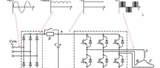
Types by method of current switching
The 220 or 380 V output voltage driver, separately highlighted in the diagram in Figure 3, which is necessarily present in any inverter, is implemented only using a pulse circuit.
The benefit of such a solution is determined by the fact that when the key semiconductor element is in a completely open and completely closed state, due to the minimum voltage or, accordingly, the minimum current, a significant reduction in the power of useless energy losses is achieved.
All this allows you to increase the overall efficiency of the device to values over 90%, Figure 4.
Figure 4. Instantaneous and average efficiency of a switching type inverter
In fact, the main losses occur at the moment of transition from one state to another, which determines the presence of additional high requirements for the key elements of the device and their performance.
The peculiarity of pulse circuits is that, unlike analogue ones, the output voltage is not pure, but so-called. approximated sinusoid.
Operating principle of a resonant type inverter generator
The resonant circuit for constructing an autonomous inverter generator is inferior in popularity to the push-pull one, incl. due to the difficulty of ensuring normal functioning at idle.
From a circuit design point of view, it differs favorably from its push-pull analogue by the possibility of implementation on only one active element (due to the rather low efficiency, it becomes ineffective at powers above 200 - 300 W).
The idea of a resonant circuit is that an alternating voltage is created by an oscillating circuit, i.e. with the correct selection of parameters and, first of all, the choice of denominations L and C, its shape will be close to sinusoidal.
A single key element or a combination of them is designed to input energy from a direct current source into this circuit, which allows you to compensate for internal losses and create the corresponding work in the load.
Depending on the type of connection of the oscillatory circuit and the load, such generators are divided into serial, parallel and partially parallel.
Additionally, a distinction is made between closed and open type circuits, the only difference between which is whether direct current flows through the inductance.
If it is present, they speak of closed circuits, and if it is absent, they speak of open resonant generators.
One of the possible circuits of the simplest resonant inverters is shown in Figure 6.
Figure 6. Simplified circuit diagram of an autonomous resonant inverter generator
Inverter design
Initially, the creation of alternating voltage in the circuit was ensured by literally switching wires from one terminal to another. This is how mechanical inverters worked, which are sometimes used today. These are rather bulky devices with low efficiency.
With the development of semiconductor technology, it became possible to change poles without the use of mechanical devices. For this purpose, thyristors are used, semiconductor devices that act as electronic keys. It is also possible to use another element base - transistors in combination with diodes. Thyristors are switched by control signals generated automatically. In the simplest case, their source can be an ordinary relay operating at strictly defined intervals. Modern inverters use software to create control pulses. This makes it possible to vary the frequency and amplitude of the alternating current.
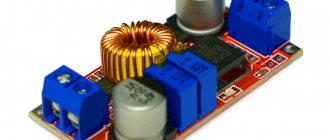
An important part of the inverter is the converter. It increases the voltage to the required value, most often from 12 volts at the battery output to 220 at the input to the thyristor bridge. Converters are often also sold as separate devices.
The use of capacitors and freewheeling diodes in circuits of autonomous resonant inverters
A certain increase in conversion efficiency is achieved by introducing various additional elements into the resonant inverter circuit. Most often, capacitors and so-called are used. freewheeling diodes.
Capacitor C1 in Figure 6 is connected in parallel with the load if it has significant inductance. The purpose of this element is to maximize the cosφ parameter.
The essence of the use of the so-called reverse diodes, which are switched in counter-parallel to each key element, is to create conditions for the recovery of energy accumulated in the reactive elements by returning it to a constant voltage source.
Any of the reverse diodes is locked in the open state of the key element and opens upon transition to the locked state, which allows you to “reset” the energy of the reactive elements L and C back to the “I” source.
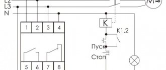
Connection diagram
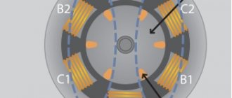
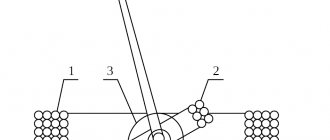
Connecting a three-phase inverter as an example can be considered in conjunction with an electric motor. The figure below shows the M engine operating under the control of keys V1 - V6. For a more visual display, all semiconductors are presented as ordinary mechanical contacts. For power supply, a constant voltage Ud is used, coming from a rectifier not marked in the diagram. Keys 1, 3, 5 belong to the upper ones, and three keys 2, 4, 6 belong to the lower ones.
The upper and lower keys are never opened at the same time to avoid short circuits. The circuit will work normally when the lower key opens, and by this time the upper one is already in the closed state. Controllers are used to form this pause.
The duration of the pause should ensure that the power transistors turn off in a timely manner. If this time period is insufficient, the upper and lower keys can open simultaneously for a very short time. This is highly undesirable and should not happen systematically, since the output transistors will become very hot and will quickly fail. This situation is known as through currents.
There is a galvanic connection between the lower and upper keys and with the control device. The control signal is supplied through resistors directly to the composite transistor, which performs the functions of the lower switch driver. The upper keys do not have a galvanic connection with the control element and with the common conductor. Therefore, for more efficient control, in addition to the driver, an optocoupler is additionally installed to the upper composite transistor. The upper switches are powered from separate rectifiers, each of which is connected to its own winding of the transformer.
Criteria for selecting autonomous inverters
When choosing a stand-alone inverter, pay attention to several main characteristics. Let us highlight the main parameters and their features.
Number of phases
When choosing the number of phases, consider the following points:
- If your home is supplied with three-phase voltage (380 V), the stand-alone inverter must also be three-phase.
- In a situation where only single-phase voltage (220 V) is connected to the machine, the equipment must be appropriate.
Nominal/peak output power
It is optimal that the rated power of an autonomous inverter is equal to the sum of the loads (consumers in the house). For reliability, it is better to buy equipment with a reserve and taking into account inrush currents.
Starting factor I is typical for refrigeration equipment, pumps and other equipment with an induction load. In it, currents at the moment of startup can be 7-10 times higher than the rated parameter.
To calculate, multiply the starting current by the voltage in the house and compare with the peak power parameter (the first indicator should be lower).
If the developer has not indicated the peak power parameter of the autonomous inverter, this means that the nominal parameter is in reality peak.
Form U out
This is a key parameter on which the quality of receivers depends.
There are three types here:
- Pure sine.
- Quasi sine wave.
- Rectangular sine wave.
To avoid operational problems and equipment damage, it is recommended to choose a stand-alone inverter with the correct sine wave.
This is because inductive loads are very sensitive to the voltage waveform. If the output of the device is a square sine wave, the main equipment will not work and may break down.
A quasi sine wave is a compromise between a pure and a rectangular sine wave. Most of the models of autonomous inverters on the market that have this characteristic are of high quality. But you need to be careful, because there are also unreliable options.
Equipment protection
A good model of an autonomous inverter should have a full range of various types of protective characteristics.
Let us highlight the main types of protection:
- from overheating;
- battery protection;
- from short circuit;
- from overload at the output.
If the model has a fan for forced temperature reduction, check with your consultant whether it functions in all situations or only turns on when the load increases above a certain value.
In the best models, the fan turns off at minimum load. As a result, the autonomous inverter produces less noise, which is important when installing it in a residential building.
Efficiency
Using the efficiency parameter, you can understand how much energy the device spends without benefit. The best representatives have an efficiency ranging from 90 to 95%. If this parameter is less than 90%, 1/10 of the energy will be wasted, which is unacceptable for solar stations.
Own consumption
The indicator displays how much power the equipment consumes without a load connected to it. It is optimal if this parameter is no more than 1% of the rated power.
For example, if the Snom of an autonomous inverter (rated power) is 3000 W, its own consumption should not exceed 30 W. If the device will be constantly connected to the network, it is better to choose a model with a low power setting.
Availability of sleep/standby mode
The essence of the option is to turn off the device if it is not used for a long time and there is no load.
In this case, the own power drops to three to six watts. At the same time, the autonomous inverter is in constant current monitoring mode in order to turn on at full power at any time.
But there is a peculiarity. To avoid difficulties with powering devices with light loads, you need the option to manually disable standby/sleep mode. In this case, the owner will be able to activate and deactivate the function himself if necessary.
If shutdown is not provided, it is possible that the autonomous inverter will remain in standby mode when a low-power load is connected, for example, charging.
In conclusion, we note that do not buy too cheap devices, because their quality may be far from ideal. It is better to choose models taking into account the manufacturer, characteristics and other parameters.
Popular models
To simplify the choice, we will consider several models of autonomous inverters, highlighting their nuances and parameters.
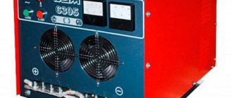
Inverter / UPS SILA EP20-300
Model SILA EP20-300 is a universal equipment that combines the options of an uninterruptible power supply, charger and converter.
It is possible to automatically switch the modes of input U from the battery or from the network. Ensures continuous operation of connected equipment.
The inverter is used as a UPS (if there is a battery) or in conjunction with a solar power plant (an external charge controller is required). Country of origin: Taiwan.
Main parameters:
- Protection against short circuit, high and low voltage.
- Fast switching - 6 ms.
- Autostart after protection operation.
- LCD display.
- Automatic charging (3-step): constant current/voltage, charge support.
- Pure sine output.
Characteristics:
- Large U range at the output - from 140 to 280 V.
- Current adjustment - from 5 to 10 A (set by program).
- Stabilization of U at the output.
- Nominal / maximum power - 300 / 900 W.
- Battery voltage is 12 V.
- Efficiency - 90%.
- Personal consumption - 24 W.
- Warranty - 2 years.
Model SILA EP20-300 is capable of operating at humidity levels from 0 to 90% and over a wide temperature range. The dimensions of the autonomous inverter are only 31.5x14.5x21 cm, and the weight is 7.5 kg. Similar models with power of 600 and 1000 W are available for sale.
Specialized 3L modules
When developing a 3L module, it is necessary to take into account that the “long” switching path also has the highest distributed inductance Ls
.
Turning off the current in a circuit with high parasitic inductance provokes a voltage surge, the amplitude of which is proportional to the rate of decay of the current and inductance: dV
=
di
/
dt
×
Ls
.
If the sum of dV
and
VDC
exceeds the blocking capacity of the power switch, it will fail.
To solve this problem, you should reduce the DC bus voltage or minimize the parasitic inductance of the switching circuit. Obviously, reducing the value of Ls
is the main goal of designers of specialized modules, since this allows the module to operate at a higher
VDC
and, therefore, have a higher power output.
Theoretically, a 3L inverter can be created using standard half-bridge modules. Possible options for constructing the circuit are shown in Fig. 12. To connect half-bridge or chopper modules, intermediate buses are required, the coplanarity of which is very difficult to ensure. In practice, these connections turn out to be quite long, which leads to high switching overvoltages. Thus, the only advantage of this solution is the ability to use standard components, but this cannot be considered a big advantage.
Since the use of 2L modules in a 3L inverter creates obvious problems, it is advisable to develop a power switch whose design satisfies the special requirements caused by the features of the 3-level topology. First of all, it is necessary to determine the optimal size of the module: to obtain maximum power, you need to use a large case and install crystals of the most accessible large size in it. However, the larger the module, the higher its parasitic inductances and, consequently, switching overvoltages. This largely limits the maximum value of the power switch current.
A high power inverter can be implemented using one large or several parallel modules of lower power. The latter solution requires an equally large number of gate control boards, the inputs of which must be parallelized. This creates known problems: increased cost, increased size, time scatter and jitter, and the need to equalize output currents. However, in a number of cases this option turns out to be optimal from both a technical and economic point of view.
From the point of view of minimizing parasitic inductances of the 3L topology, at high rated currents, the SEMIKRON SKiM4 design is the most preferable. The specialized modules of the MLI family (see table) use crystals with a blocking voltage of 650 V (rated current IC
= 600 A) and 1200 V (
IC
= 300 A).
This allows the converter to provide output power up to 260 kVA ( VDC
= 800/1500 V,
Vout
= 480/1000 V).
To further improve it, you can use the parallel inclusion of MLI modules. Table.
Range of produced 3-level IGBT modules
| Module type | [email protected] °C, A | VCE(sat)@25°C, V | [email protected] °C, mJ | Rth(js), °С/W | ML schema |
| SK 20MLI066 | 20 | 1,45 | 1,5 | 1,95 | |
| SK 30MLI066 | 30 | 1,45 | 2,7 | 1,65 | |
| SK 50MLI066 | 50 | 1,45 | 3,4 | 1,11 | |
| SK 75MLI066 | 75 | 1,45 | 4,5 | 0,75 | |
| SK 100MLI066 | 100 | 1,45 | 6,7 | 0,65 | |
| SK 150MLI066 | 150 | 1,45 | 8,8 | 0,55 | |
| SKM 150MLI066T | 200 | 1,45 | 5,4 | 0,29 | |
| SKM 200MLI066T | 280 | 1,45 | 11 | 0,21 | |
| SKM 300MLI066T | 400 | 1,45 | 13,6 | 0,15 | |
| SKiM 300MLI066HD | 280 | 1,45 | 0,26 | ||
| SKiM 400MLI066HD | 330 | 1,45 | 0,23 | ||
| SKiM 200MLI 12E4 | 256 | 1,8 | 0,2 | ||
| SKiM 300MLI 12E4 | 373 | 1,8 | 0,2 |
Notes:
Ic is the rated collector current; VCE(sat) — saturation voltage; EON + EOFF - total energy losses; Rth(js) — thermal resistance “crystal-heat sink”
The main advantage of the 3-level class 12 module is the ability to achieve a maximum AC output voltage of 1000 V. This ensures compliance with the low voltage directive and the ability to apply the corresponding low voltage standards, as well as reducing the converter current without changing the output power.