Single-phase voltage monitoring relay: connection diagram
A 1-phase voltage control relay is used to protect household appliances from voltage surges in the home electrical network. In an emergency, this device instantly disconnects an apartment or a separate load from the power circuits, and after normal power is restored, it automatically turns on again. There are two known designs of protective relays of this class, one of which is represented by devices with automatic time delay. The second models have a simpler design; the delay time is set manually.
Checking pH using a multimeter
Full tests can be carried out using special equipment in an electrical laboratory. However, the accuracy of the output voltage readings can be checked with a conventional multimeter. The device must be switched to the mode for measuring alternating voltage up to 700 V. This is indicated on the switch as “ACV 700”.
Then use a multimeter to determine the voltage at the output of the LV and compare this value with the readings on the display of the protective device. You need to understand that both devices have some measurement error. The readings should be approximately the same. A difference of 2-3 V is not a reason to panic. But if the differences are more significant, then there is a malfunction in the launch vehicle.
The use of LV will protect household electrical appliances from voltage surges. To do this, you will need to select the correct settings for its operation. Approximate values can be found in the device data sheet.
The voltage control relay is selected taking into account the number of supply phases and the maximum power of the consumer. It is advisable to purchase a protective device with a current reserve of 20-30%. If you need to control the current consumption, it is better to install a device with a built-in ammeter.
General structure and operating features
According to the method of installation into the serviced line, the single-phase voltage relay also has two versions. One of the varieties is made in the form of a remote device connected to a regular outlet, and the other is similar to a module mounted on the DIN rail of the input distribution panel.
Any single-phase voltage control relay, regardless of its type, includes the following mandatory components:
- An electronic module through which the lower and upper operating limits of the device are set and controlled.
- Control signal generation block.
- An actuator in the form of a relay that turns off the LV when the voltage exceeds the permissible limit (set point).
Types of launch vehicles
Various types of devices need protection from voltage surges. Some of them operate on household voltage 220 V and consume minimal power. Examples of such devices include smartphone chargers or LED light bulbs. Others also operate on 220 V, but already consume thousands of watts of power, for example, electric kettles and irons. Still other devices require three-phase power supply of 380 V. A conventional single-pole LV is not suitable for them. Among such consumers are industrial machines and powerful asynchronous motors. Therefore, all relays for voltage control are usually divided by type of housing and type of load.
By case type
This classification indicates which devices and in what quantities can be connected to the relay. According to the type of execution, the launch vehicle is divided into 3 types:
- rosette;
- in the form of an extension;
- with installation on DIN rail.
The first type is the easiest to use. This surge protection relay plugs directly into an outlet. On one side of the case there is a corresponding connector in the form of a plug. On the other part of the device there is a standard socket for connecting the load. This type of LV can be quickly removed and connected to another location.
The second type is made in the form of an extension cord. On its surface there are several sockets for loading. Unlike type 1, this relay is equipped with a cable and plug. The device is convenient for stationary connection of office equipment.
The third type is the most professional. The pH is installed in the shield. It has an extended list of functions, high throughput, and at the same time protects all electrical appliances in the apartment.
By number of phases
Electrical consumers operating on alternating current are divided into 2 groups. The voltage control relay has a similar division. Namely:
- single-phase LV;
- three-phase.
Single-phase modification is suitable for home use. These relays are installed in apartments, garages and cottages. They pass through one phase and zero. That's why they are called single-phase.
The operating voltage for such LVs is 220V. Their contacts are designed for a current of 30-40 A, which corresponds to the maximum values for residential wiring. The device has a minimal list of settings and, if you read the instructions, is suitable for use by an ordinary person without specialized education.
Three-phase voltage monitoring relay ZUBR 3F
The second type of relay is more complicated. It controls voltage on 3 phases simultaneously. This modification is suitable for units consuming 380 V from a network. The relay has an expanded list of adjustments and requires minimal experience in setting up automation systems.
Advantages of installing a single-phase current transformer
The need to use voltage relays in apartments and private houses arises for a number of reasons, the most important of which is the desire to protect household appliances connected to the network. In addition, it protects the circuit breakers located in the distribution panel from overloads.
Usually the protective device is installed after the electric meter, but in some cases, with special permission, it can be connected before it. With this connection option, the LV provides protection for an expensive energy meter, preventing unjustified expenses for purchasing a new one.
A single-phase overvoltage relay, in addition to automatic overload protection, allows you to manually set response thresholds and visually observe the set values on the display screen. The voltage values acting at the output and input of the protective device are also displayed here.
Learn more about each feature
- dE1 - Overvoltage, undervoltage and overcurrent protection, automatic shutdown/on. Application: basic protection mode.
- dE2 - Overvoltage, undervoltage and overcurrent protection, automatic shutdown / manual turn on (press up/down buttons simultaneously twice after the delay time has elapsed). Application: if there is a risk of equipment failure when automatically turned on in the absence of observers. dE3 - Disable overvoltage, undervoltage and overcurrent protection functions, the load is always disconnected. Application: for repair work.
- dE4 - Disable the overvoltage, undervoltage and overcurrent protection functions, the load is always on. Application: Any equipment must not be accidentally de-energized.
- dE5/6/7 - Disable the overvoltage, undervoltage and overcurrent protection functions, the load is turned on/off cyclically (Timer). Application: in greenhouses, greenhouses, poultry houses, incubators... for turning on/off lights, heaters.
- b9 - Backlight mode, 1 - always on, 2 - will be on for 30 seconds after the last button press.
- SS — Load turn-on delay after power-on, 2-255 sec.
- Uo - Overvoltage protection value, 85-300V, can be disabled (off).
- UoH - Overvoltage recovery value, 85-300V, this value must be less than the overvoltage protection value or it will default to −5V overvoltage protection value when saving. The load will turn on when the voltage drops below this value.
- UL - Undervoltage protection value, 85-300V, can be turned off.
- ULH - Under-voltage recovery value, 85-30V, this value must be greater than the under-voltage protection value or it will default to +5V under-voltage protection value when saving. The load will turn on when the voltage rises above this value.
- SU — Shutdown delay due to over/undervoltage, 0.1-60 sec. This means that if the fault is not resolved within this time, it will disconnect the load.
- Io - Overcurrent protection value, 1-80A, can be turned off.
- IC - Resistive load protection value, 0.5-5A, can be turned off.
- SI - Overcurrent shutdown delay, 0.1-60 sec, this means if the fault is not resolved within this time, it will turn off the load.
- SH — Load turn-on delay after disconnection by current protection, 1-512 sec. This means that after this time the LV will turn on the load again, but if the overload is not eliminated, it will turn off again (when the delay time has expired).
- OP - Off time (after switching on) cycle in modes 5/6/7, 1-999, time unit is different in modes 5/6/7 (5-sec/6-min/7-hour).
- CL — On time (after off) cycle in modes 5/6/7, 1-999, the time unit is different in modes 5/6/7 (5-sec/6-min/7-hour).
- Er1 - Last five security records showing the reason why the security was turned on. You can view it in the function menu, the last item, using the “up” and “down” keys.
Here is a list of possible reasons for protection:
- overvoltage protection
- undervoltage protection
- overcurrent protection
- resistive load protection
- (I didn’t see if there is a possible PH failure!) But in fact, only two cells work, the last 3 cells copy the 2nd one. Thus, not the last five records of the protection reason (Er1-Er5), but only two (Er1-Er2/Er3/Er4/Er5). Therefore, the third time the cycle begins again.
After 7 emergency situations it looks something like this:
Error transfer 0–5
There are only two cells working there instead of five. In the last three, the readings from the second are copied: some new cycle occurs, and logically it should constantly shift when a new error value appears in the first. Although this does not affect performance, it’s such a jamb! Perhaps there was something wrong with the software.
Technical characteristics of the device
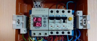
The single-phase voltage relay, mounted on a DIN rail, has the following performance characteristics:
- current voltage in the network (220 Volts);
- rated load current;
- lower and upper overload response limits;
- delay time before restarting the machine.
The characteristics of a voltage relay plugged into a socket are practically no different from the parameters of stationary protective devices. Their only difference is that the amount of switching power is limited to 3.6 kW - just over 10 Amperes in current. In this case, there is no question of using a magnetic starter with contactors - there is simply nowhere to put it.
Settings
Manufacturers Novatek-Electro, when developing this relay, met people halfway and programmed the basic functions into this device, leaving the user with a simple choice from several options, such as:
- automatic restart time (AR) from 5 to 900 seconds (15 minutes);
- lower cut-off threshold (Umin) from 160 - 210 volts;
- upper cut-off threshold (Umax) from 230 - 280 volts.
By rotating the potentiometer RN-104, the indicator displays a digital representation of the parameter, which is undoubtedly convenient and does not require guessing.
We recommend setting the voltage relay characteristics as follows:
- AR time 180 seconds;
- Umin 190;
- Umax 245.
In practice, there are times when the voltage practically coincides with the set threshold for quite a long time and in order to avoid continuous switching on and off of the relay, a hysteresis of 4-5 volts from the set one is introduced. In this case, the device automatically introduces an additional threshold and will not turn on until the voltage drops below the set hysteresis value. If this phenomenon is cyclical and repeats periodically, then review the parameter settings and change them.
It is worth mentioning separately about the distinctive features of the volt control RN-104 Novatek Electro. To avoid false shutdowns during operation, intelligent monitoring of the network status is installed. If the voltage gradually increases and goes beyond the set limits, but not higher than +30 volts from the set threshold, the relay waits 1 second before turning off. With a sharp jump above the set threshold of more than +60 or above 285 volts, the relay operates instantly in 0.02 seconds.
It is known that when a powerful consumer is turned on, a voltage drop occurs; they can be a refrigerator or an air conditioner. When the voltage drops smoothly below the set threshold by -60 volts, the device waits 7-12 seconds, which is enough to start the consumer’s engine. If the voltage drops below 145 volts, the device fires in 0.12 seconds.
You can clearly see the principle of operation of the voltage relay in the video below:
How does RN-104 work at 40 A
By the way, the manufacturer guarantees the relay operating time for 10 years, and warranty support for 5 years.
Overall, the device looks powerful and reliable, so when you decide to buy Volt Control, make a choice in favor of the device described in our article, we leave a positive review about it. This concludes our instructions for describing the device, purpose and operating principle of the RN-104 40 A voltage relay.
Useful on the topic:
- Low voltage in the network - where to complain
- How to connect a motion sensor for lighting
- How to connect the stabilizer to the network
Connection diagram
Before connecting a single-phase voltage relay to a DIN rail, it is advisable to carefully study the internal structure of the electrical cabinet. Typically, these devices are connected after the electric meter into the gap between the phase and neutral wires. With this choice of installation location, the LV will cut off exactly the “phase” along with the neutral supplied through the cable. This is the only way to achieve reliable operation in the event of severe voltage surges.
In practice, two well-known schemes for connecting single-phase relays to the consumption line are used:
- with direct connection to the load;
- with connection of power equipment through contactors included in the magnetic starter.
According to the PUE, parallel connection of several protection devices is allowed, each of which can be connected to a separate group of loads.
A good result in this situation can be achieved through the use of a special three-phase LV, designed to operate in 380 Volt power circuits.
A look at industrial protection devices from a technical (engineering) point of view
Let us note, first of all, that all simple heating devices are not afraid of large voltage deviations from the norm (the deviation can be up to +/- 40 Volts). Therefore, it is inappropriate to turn them on after the stabilizer, unnecessarily loading it. A stabilizer is needed mainly for a refrigerator if the voltage drops to 180-190 Volts for a long time.
In all cases of resolving issues of stabilization or other protection, it is necessary to take into account that:
- Stabilizers have a so-called “no-load current” (no load), which is continuously added to the load current. Therefore, in many cases, especially when powering low-power electronic equipment, the total electricity consumption will be much higher (the stabilizer, as a rule, does not turn off or turn on with the load). All manufacturers indicate efficiency for rated load.
- Most stabilizers do not have surge protection devices in cases of lightning or in the event of a break in the neutral wire in the electrical network (or they have the simplest ones, with a factory setting). The response time of the protection, as a rule, is more than half a voltage cycle, which is too dangerous when the voltage surge exceeds 300 V. It must be taken into account that the voltage controlled by the stabilizer and causing certain switchings continues to increase at the input of the power supply of the TV or other consumer for the entire time the protection is activated ( load disconnection), and these surges (impulses) often have a steep front.
- According to their operating principle, stabilizers pass short (up to several milliseconds) overvoltage pulses, so the quality of the output voltage is determined by additional filtering, which may be insufficient for some electronic equipment.
- Voltage stabilization during a drop in the network is not required for modern electronic consumers; they have their own stabilization in this zone.
- Voltage relays installed in a panel or on a socket (as an adapter) have relay settings for disconnecting the load when the voltage increases or decreases above the set values (manually adjustable). That is, there is a very unpleasant and even harmful functional feature for the consumer. For all, usually expensive, equipment, it is strictly necessary not to allow the voltage to exceed 250 V. At the same time, in many electrical networks, especially in dacha and village networks, this excess is very likely. Thus, there are frequent shutdowns of the TV and all other consumers, which quickly becomes boring and leads to an increase in the setting to 260 V and higher if the user is technically illiterate. The risk of equipment damage increases sharply (one must also take into account the response delay, which is also manually adjusted and can be dangerously long). To reduce the psychological impact of frequent shutdowns, the developers made automatic restoration of the protection device with a certain (configurable) delay. But, in many cases (especially for a computer), this will not allow users to maintain peace of mind and especially the fruits of long work at the computer.
- The vast majority of protective devices in the form of splitters or adapters that are widely available for sale do not have the protection indicated on the bright packaging at all. Most often, they have only a low-power varistor, which begins to somehow dampen the voltage (according to its characteristics, in microseconds) after about 350 V. But, the same voltage will be simultaneously applied to the input elements of the power supply of any electronic equipment, with a high probability of their breakdown and burning!
Thus, the situation regarding solving problems of surge protection does not seem to be as favorable as on store shelves and on the websites of leading Manufacturers.
Selection of protective device
Before choosing a protective device of one type or another, it is important to determine its operating parameters, which are optimally suited for specific conditions. If the user is concerned about the safety of expensive household models of a washing machine or an imported refrigerator, it is wiser to purchase a sample of the “socket-plug” type.
This choice is justified only on the condition that all other equipment is already reliably protected by the stabilizer. In this case, installing a collective relay in the electrical panel will be unnecessary and will lead to unnecessary costs. The “socket-plug” option is more suitable for city residents who decide to save money on installing a LV, since its installation will require inviting a local electrician. When calculating possible costs, it is necessary to understand that the purchase of several devices plugged into an outlet will, in any case, cost more than one stationary LV.
If the user does not have a stabilizer, and also if the apartment owner wants to reliably protect household equipment, it is wiser and cheaper to choose a device mounted on a DIN rail. By connecting several voltage relays in parallel, the possibility of breakdown of expensive equipment is virtually eliminated. In addition, these devices can be installed in private households, providing voltage control in a three-phase network (one for each phase).
The choice of connection diagram for the voltage relay is determined by the operating conditions at the intended installation location. When selecting it, one should take into account the values of currents in the load, which can reach maximum values. In this case, it is not allowed to connect the relay directly to the serviced circuit according to the PUE. An additional element will have to be introduced into the circuit - an electromagnetic starter, the contactors of which can withstand significant current loads.
All electrical networks periodically experience power surges that can damage electrical equipment. Network surges are especially dangerous for electronics. To protect themselves from them, people use stabilizers and voltage relays. Let's look at what it is and how to connect a voltage relay.
Overvoltage due to switching
This phenomenon can occur when devices that produce a high inductive load are connected to or turned off in the line. These include power supplies, electric motors, and powerful tools powered from the mains.
This effect is due to the laws of commutation. An instantaneous change in the current value in the solenoid, as well as the potential difference across the capacitor, cannot occur. When a circuit with such a load is connected or opened, the appearance of an electric potential caused by self-induction and switching processes is noted at the point of contact.
The transient process is always accompanied by a surge of voltage, which has the opposite polarity to the input. The small capacitance of the conductors in the network causes a resonance that lasts a short time and causes high-frequency oscillations. At the end of the transition process they fade out.
How long the overvoltage will last and what its magnitude will be depends on the following indicators:
- Load inductance.
- Instantaneous value of the potential difference during switching.
- Capacity of connecting electrical cables.
- Reactive power.
Voltage control relay 1-phase
The quality of the current and voltage entering the home through the electrical network has a huge impact on the household appliances and equipment installed here. Jumps and drops that occur in the network significantly reduce the performance and service life of equipment. In order to prevent and eliminate such negative effects, many owners use a single-phase voltage control relay, installing it in the panel along with other protective devices. This measure is especially relevant on old lines, as well as on substations and transformers where modernization or reconstruction has never been carried out.
Why is high voltage dangerous?
We figured out why increased voltage occurs in the electrical network, but what is its danger? This phenomenon on the network is dangerous primarily for household appliances. Although modern devices install switching power supplies with stabilized output circuits, their input stages experience increased loads and may fail prematurely.
Heating devices are also affected - boilers, electric stoves, heating elements of washing machines, etc. Due to the high voltage, increased current flows through their spirals. Accordingly, more power is released and service life is reduced. This is especially dangerous for air heating elements, for example, convector filaments and spirals.
Such a problem with the electrical network is also unfavorable for equipment with engines, such products include refrigerator compressors, air conditioners, fans and pumps. Their windings will heat up and may eventually fail. The same applies to network transformers.
Do not forget that since the high voltage increases the current consumption, the wiring is also loaded. At best, the consequences will lead to damage to contact connections (especially if there are twists), and at worst, to burning of wires, melting of insulation and fire.
General voltage relay device
The design of these devices consists of two main parts. This is an electronic part that controls voltage and a power part in the form of a load disconnector. Both parts are placed in a common housing.
The electronic part is made on the basis of a microprocessor or a conventional comparator - an operational amplifier that compares the signals of the direct and inverse inputs. The microprocessor version allows you to more smoothly adjust the upper and lower response thresholds.
The main indicator of the operation of a voltage relay is its performance. In some devices, this parameter can be only a few tens of nanoseconds. The response threshold is set using a potentiometer on a scale with a special graduation.
A single-phase voltage relay differs from a stabilizer in its main function. It does not equalize the mains voltage, but performs an instant shutdown of the protected area in the event of voltage surges upward or downward. After the network voltage has stabilized, the area is automatically reconnected to power. Restarting is carried out with a certain delay using a timer, thereby ensuring the correct operation of electronic household appliances. The delay time can be adjusted and set within the desired limits. Such capabilities of the device provide maximum effect in case of phase imbalances, overloads, neutral breaks and other emergency situations that occur with phases.
A single-phase control relay has a more compact size compared to any types of large stabilizers. This allows you to install the device directly into the panel on a DIN rail and quickly connect the necessary wires. The stabilizer requires a separate box, mounted near the panel or inserted into the existing network when installed inside the apartment. In terms of speed, only expensive triac-type stabilizers can compare with voltage relays. In addition, relays operate practically silently, while stabilizers make a lot of noise during operation.
Which is better: stabilizer vs relay
Often, instead of connecting a control relay in the panel, electricians recommend installing a voltage stabilizer in the house. In some cases this may be justified. However, there are a number of nuances that must be remembered when choosing one or another option for protecting electrical appliances.
In terms of functionality, the stabilizer not only equalizes the voltage, but also turns off when the voltage is too high. A voltage relay is an exclusively protective automatic device. It seems that the first includes the functions of the second.
But compared to the RKN stabilizer:
- more expensive and noisy;
- more inert during sudden changes;
- does not have the ability to adjust parameters;
- takes up much more space.
When the input voltage is reduced so that the output of the stabilizer has the required indicators, it begins to “draw” more current from the network. And this is a direct path to wiring burnout if it was not originally designed for this.
The second main disadvantage of the stabilizer in comparison with the control relay is its inability to intercept a sharp voltage surge when the zero is broken.
Literally half a second with 350-380 W in the outlet is enough for all the equipment in the house to burn out. But most stabilizers are not able to adapt to such changes and pass high voltage, turning off only 1-2 seconds after the start of the surge.
In addition to stabilizers and relays, overvoltage and undervoltage releases can also be used to protect the line from voltage surges in the network. But they have a longer response time compared to the RLV. Plus, they do not turn the power back on automatically; their operation is more like an RCD.
After a power outage, these releases will have to be reset manually.
Characteristics
The main job of the monitoring relay is to constantly measure the effective voltage value. If the nominal value is exceeded or, conversely, it decreases below the established norm, the power contact of the device opens and the phase is disconnected. Thus, the external supply network is disconnected from the internal wiring.
All devices of this type are divided into single- and three-phase. In the first case, only one phase is switched off, and in the second case, all three phases are switched off simultaneously. If a three-phase connection is used in domestic conditions, for protection it is recommended to install single-phase monitoring relays, individually for each phase. In this case, voltage surges occurring in one phase will not cause shutdowns of other phases. The three-phase protective devices themselves usually monitor the voltage on electric motors and other similar consumers.
One of the most important characteristics of single-phase devices is the current load. It is this parameter that makes it clear what electrical power is allowed to pass through a particular device. The current load is primarily taken into account when choosing a particular device.
Common Mistakes
Often, when choosing a single-phase relay, a mistake is made due to incorrect selection of current. Often the current rating is simply set without taking into account the required power reserve of at least 30%.
A common mistake is incorrectly setting the upper and lower limits of the relay operation, as well as the operation time. For powerful devices, it is recommended to set it to 300 seconds, which will delay their reconnection as much as possible and help avoid damage.
- How to install a distribution box for electrical wiring in a brick, concrete wall
- Reasons for triggering the automatic device
- Selectivity of electrical network protection - what is it?
- What is a power limiter (application)
- How to check your electricity meter readings
Connection diagram
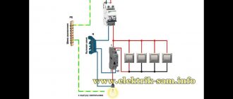
Connecting single-phase voltage control relays to a 220 volt network can be done in two ways:
- The first option involves direct control of the load by relay contacts, through which all consumed current flows.
- In the second case, the relay contacts are controlled through the contactor winding. Power contacts are used to connect the load to the network. Due to this, the contacts of the relay itself are unloaded and the reliability of its operation is increased.
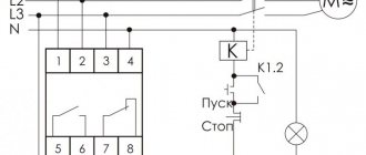
Most often, the first connection diagram is used, when the control relay is installed behind the meter. The phase wire coming from the meter is connected to terminal 2. Then, through the power contact, the phase is supplied from terminal 3 to the home network. The neutral wire is connected to terminal 1 and provides power to the microcircuit of the relay itself. Thus, there will be no zero break, and only the phase wire is used to control the contacts.
Power is supplied to the control relay after the input circuit breaker is turned on. If the voltage is within normal limits, then after a while the contacts of the device close and current begins to flow into the network. The turn-on delay time is adjusted using the buttons located on the front panel. When the voltage jumps, for example, upward, the upper threshold of 250 volts is exceeded. This change is recorded by a protective device, after which the power contact is opened and the phase wire is subsequently broken. Thus, household appliances and equipment are protected from overvoltage.
After the voltage returns to the operating range, the contacts close again after a set time delay and the circuit returns to its operating position. The device reacts in the same way to an unacceptable voltage drop.
This connection diagram requires the selection of a control device that exceeds the current parameters of the input circuit breaker. This reserve will protect the relay if it receives maximum load. You don’t have to make such a choice if you use a relay in conjunction with a contactor, when two devices are combined in one.
Possible rational solution to security problems
My own experience in developing the most cost-effective and, in my opinion, promising protection devices led to the following solution (which has been successfully tested in prototype models, is patentable, or is the subject of “know-how” - under an appropriate agreement with an interested Manufacturer).
To eliminate the shortcomings of stabilizers and voltage relays, it is advisable to implement a cutoff of the excessive voltage amplitude in the range of 250-290 Volts of the input voltage (the most likely excess) and an instantaneous cutoff at a higher voltage. This is possible by introducing an active ballast with a powerful Darlington transistor (or two simple ones) into the power circuit. To increase the permissible power of consumers, it is possible to install a miniature fan (12 V) with a simple power supply for chargers. In this case, the 12/5 Volt transition is achieved very simply - by switching an additional zener diode in the charger circuit. That is, the protection device acquires the additional function of a charger.
Implementation of ballast control according to the principle noted above (synchronous amplitude cutoff, including all pulses) does not require the use of any controllers. Moreover, in recent new work on the circuit, it was possible to get rid of the relay for turning on the amplitude stabilization mode and, accordingly, from the electrolytic capacitor (there are none at all), thanks to the development of an original constant current switch on a thyristor (with hysteresis), which turned out to be very successful in the circuit used protection devices (judging by the author’s experience and the search for analogues, it can be considered an invention).
In standby mode, the control board consumes less than 0.5 W (depending on voltage). For instantaneous cut-off (about 1 ms), the author also developed and successfully tested (for several years, in different devices) the design of a relay release based on a thermal breaker type VK-1-10, widely used in network filters-splitters. However, due to the synchronous amplitude cutoff at the level of 250 V, up to 280–290 V of the mains voltage, the likelihood of a larger overvoltage is significantly reduced, so it becomes rationally justified to use a simple fuse, which is simply burned out by a powerful thyristor (with some current limitation) for a sufficiently long time for this purpose, an overvoltage pulse (taking into account the duration of the half-wave decay of the mains voltage). It should also be taken into account that the current through the fuse (about 20–40 A) “raises” the network voltage (due to its resistance).
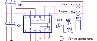
Relay and contactor operation diagram
An additional connection of a contactor becomes advisable in cases where excessive currents are regularly switched. Such a scheme will cost much less than purchasing a relay with the appropriate parameters. The rated current of the relay will no longer matter, since the entire current load will fall on the contactor, which has the necessary safety margin. The only drawback of this scheme is a slight decrease in performance. In this case, it takes time for the relay to operate and additional time for the contactor to operate.
In order to connect them together, we first use a diagram for connecting the power phase wire from the machine at the input to input 1 of the contactor, that is, to its power circuit. A separate wire with a smaller cross-section is used for the phase input of the control relay, since the loads on it will be insignificant.
This wire is connected not only to the output contact of the machine, but also to the input terminal of the contactor. Since it has a small cross-section, being connected to the same socket with a normal wire, it can easily jump out. To avoid this situation, a thin conductor is wound onto a thick wire and covered with a layer of solder. Sometimes crimping is done for such twisting using a special tip.
The relay output also uses a small cross-section wire connected to terminal 1 of the contactor coil. Terminal 2 together with the relay neutral wire are connected to the common neutral bus without any problems.
Manufacturer analysis
Voltage relays are manufactured by many manufacturers with factories located throughout the world. The table below shows the most popular models in our country, indicating the manufacturers and type of device mounting.
| Model | Manufacturer country | Response thresholds V | Rated current A | Degree of protection | Workmanship |
| ZUBR D16 | Ukraine | 120-210 ; 220-280 | 16 | IP 20 | Higher |
| Adecs ADC-0110-40 | Ukraine | 100-400 | 0-40 | IP 20 | Higher |
| Sven OVP-11F | Finland | 185-255 | 10 | IP 20 | Higher |
| Novatek RN-111 | Ukraine | 160-220; 230-280 | 16 | IP 40 | Higher |
| TESSLA D32 | Ukraine | 120-210; 220-280 | 32 | IP 20 | Higher |
Selection of protective device
By comparing all the costs, expenses and inconveniences associated with the use of stabilizers, it becomes much easier to choose a suitable 1-phase voltage control relay. In any case, you should carefully study the features and parameters of your home electrical network. You can use special testers that record the characteristics of incoming power over a certain period of time. If during the test no long-term power surges are detected, then it is recommended to use a conventional relay to protect the network, without unnecessary additional and expensive functions.
There are several types of such devices that are most suitable for home use:
- The most widely used devices are those mounted in a panel or distribution cabinet. They are able to protect not only individual consumers, but also the entire apartment or private house. They have a wide range of adjustments and can operate in different modes. The connection diagram for these relays assumes their use both independently and together with contactors.
- Relay in the form of a plug-socket. They are installed directly into an electrical outlet and protect one or several consumers at once. The microcontroller analyzes the state of the current voltage, and the received data is displayed on the display. If necessary, the load is switched off using an electromagnetic relay. Permissible limits and delays are set using button combinations.
- RKN extension cord. Works similar to a socket plug. The only difference is the presence of two or more outlets, which allows you to protect several electronic household devices at once.
{SOURCE}
Causes and danger of power surges
When there is a voltage drop in electrical networks, its amplitude changes for a short period of time. After this, it is quickly restored with parameters close to the initial level.
Such an electric current impulse lasts literally for several milliseconds, and its occurrence is due to the following reasons:
- Lightning discharges. They cause voltage surges of up to several kilovolts, which no device can withstand. Such fluctuations often cause network outages and fires.
- Overvoltage caused by switching processes when high power consumers are connected or disconnected.
- The phenomenon of electrostatic induction when connecting electric welding, commutator motors and other similar equipment.
The danger of consequences from overvoltages is clearly reflected in the figure, where lightning and switching impulses differ significantly from the rated mains voltage. The insulating layer in most wires is designed to withstand significant differences and breakdowns usually do not occur. Often the pulse does not last long and the voltage, passing through the power supply and stabilizer, simply does not have time to rise to a critical level.
Sometimes the insulation layer of a 220 V network may not withstand the increasing voltage. As a result, a breakdown occurs, accompanied by the appearance of an electric arc. For the flow of electrons, a free path is formed in the form of microcracks, and gases filling the microscopic voids serve as a conductor. This process is accompanied by the release of a large amount of heat, under the influence of which the conductive channel expands even more. Due to the gradual increase in current, the operation of the automatic protective equipment is slightly delayed, and these few moments are enough to damage all the electrical wiring in a private house.
Particularly dangerous are high and low voltages that remain in this state for a long time. This mainly happens due to emergency situations that need to be eliminated in order for the current to return to normal. There are no other methods of normalization or any special devices that protect against this phenomenon.
How protection works
The operating principle of a voltage relay is simple. The device has a built-in network load monitoring unit. Control parameters are usually set by the manufacturer. But the owner has the right to set his own limits.
The block is constantly busy measuring the voltage on the line. And if it deviates from the norm in any direction, then a signal is instantly sent to the executive module. The latter immediately switches off the load on the line, saving working devices.
But the measuring unit continues to operate in cyclic mode. After a certain period of time, the module takes readings from the line. If violations persist, then the automation is inactive. She waits for the next time period for measurements.
Voltage monitoring device Source prom.st
It can also be installed manually. Or leave the factory settings. When the measurements show the specified norm, the executive unit is also notified about this. And it closes the power contact, renewing the connection to external power sources.