How to turn a “minus” into a “plus” and vice versa? How to hook up to an electric drive? How to open the trunk with the alarm key fob? How to block the engine from starting? There is an answer to all these questions: using a relay.
Knowing how a relay works, you can implement various connection schemes to the car's electrical wiring.
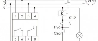
Usually the relay has 5 contacts (there are also 4-pin and 7-pin, etc.). If you look at the relay carefully, you will see that all contacts are signed. Each contact has its own designation. 30, 85, 86, 87 and 87A. The figure shows where and what contact is.
Pins 85 and 86 are the coil. Contact 30 is a common contact, contact 87A is a normally closed contact, contact 87 is a normally open contact.
At rest, i.e., when there is no power to the coil, contact 30 is closed with contact 87A. When power is simultaneously supplied to contacts 85 and 86 (one contact is “plus” and the other is “minus”, no matter where it is), the coil is “excited”, that is, it is triggered. Then contact 30 is disconnected from contact 87A and connected to contact 87. That’s the whole principle of operation. It seems to be nothing complicated.
A relay often comes to the rescue when installing additional equipment. Let's look at the simplest examples of using relays.
Engine lock
The blocked circuit can be anything, as long as the car does not start if the circuit is broken (starter, ignition, fuel pump, injector power, etc.).
We connect one coil power contact (let it be 85) to the alarm wire, on which a “minus” appears when arming. We apply +12 Volts to the other contact of the coil (let it be 86) when the ignition is turned on. Contacts 30 and 87A are connected to the break in the blocked circuit. Now, if you try to start the car with the security switched on, contact 30 will open with contact 87A and will not allow the engine to start.
This scheme is used if you have a “minus” from the alarm to blocking when arming. If you have a “minus” from the alarm to blocking when disarming, then instead of contact 87A we use contact 87, i.e. The open circuit will now be on pins 87 and 30. With this connection, the relay will always be in working condition (open) when the engine is running.
Selection of solid-state relays, protection and operating features
A conventional relay and contactor can withstand short-term overloads of up to 150 and even 200% of the nominal without any problems. Especially if you do not switch the load with such a current, but increase the current after closing, and lower it before opening.
Ordinary contacts can withstand short-term short-circuit current if the protection with the correct current setting is activated. You just might have to clean the contacts later.
Solid-state relays suffer more from overloads; within half a period they deteriorate irrevocably, and the contacts cannot be cleaned later due to the lack of them.
If when choosing a contactor it is enough to select a margin of 10-20% and protect it with a conventional automatic machine, then with solid-state devices everything is more complicated.
Therefore, for solid-state relays, it is recommended for active loads (lamps, heating elements) to have a rated current reserve of 2-4 times. When starting asynchronous motors, due to the large starting current, the current reserve must be increased to 6-10 times.
That is, the three-phase solid state Fotek TSR-40AA-H 40A, shown in the photo just above, is unlikely to work at its 40 amperes. The motor power that can be switched in this case is from 2.2 kW to 5 kW. Moreover, a 5 kW engine (this is about 10A) must be started at idle, with a minimum starting torque, and a load can be applied to it after start-up and acceleration.
By the way, solid-state relays can behave inappropriately with an inductive load; I had problems. In the case of highly inductive loads (transformers, coils with magnetic cores, electric bells, etc.), it is necessary to connect an RC circuit (snubber circuit of a series resistor and capacitor) in parallel with the load to reduce the influence of back-EMF. In addition, this circuit reduces the overall load inductance, i.e. makes her more active. And TTP is easier to work with.
Opening the trunk using the car alarm key fob
If your car has an electric trunk drive, you can connect to it with a car alarm to open it using the alarm key fob. If the alarm outputs a low-current signal to open the trunk (and most often this is the case), then we use this circuit.
First of all, we find the wire to the trunk drive, where +12 Volt appears when the trunk is opened. Let's cut this wire. We hook up the end of the cut wire that goes to the drive to pin 30. We hook up the other end of the wire to pin 87A. We connect the alarm output to contact 86. We connect contacts 87 and 85 to +12 Volts.
Legislation
Before practicing installing DRLs, I would like to dwell a little on the legal standards for installing DRLs, as well as the rules of their operation.
The very first and basic rule is that unauthorized installation of additional light signals on a car is prohibited. Yes, you are right, you do not have the right to install DRLs on your car if it was not equipped with them by the manufacturer. This will be considered as making changes to the design of the vehicle. For every change to a vehicle's design, a certificate must be obtained, which in itself is neither quick nor cheap. Otherwise, traffic police officers will issue you a fine, or even take your car to the impound lot.
How so? My neighbor installed DRLs on the Oka and drives calmly! - you ask. He is simply lucky to have loyal traffic police officers who do not pay attention to his DRL - I will answer you.
Once again, unauthorized installation of additional light signals on a car is prohibited if it was not equipped with them by the manufacturer. Therefore, you make any changes to the design of the vehicle at your own peril and risk. It’s a completely different matter if your car’s equipment does not include DRLs, but the more expensive trim levels of your model do have DRLs. In this case, you have the right to install DRL without any approval from the certifying authorities.
The first rule for installing DRLs concerns their location on the car body (see picture). If we briefly describe this figure, we get the following:
- DRLs should be installed at a height of 250 to 1500 mm;
- The distance between adjacent edges of the DRLs must be at least 600 mm;
- The distance from the outer side surface of the vehicle to the nearby edge of the DRL should be no more than 400 mm.
Now let’s briefly go through the rules of operation and use of DRLs:
- DRLs should only be used during daylight hours;
- It is prohibited to use DRLs in conjunction with side lights, low and high beam headlights, as well as fog lights.
Everything that is not prohibited is permitted. It's that simple. Separately, I would like to dwell on an important point, it concerns the use of DRLs in conjunction with high beam headlights. The rule goes something like this: When the high beam signal is briefly signaled, with the side lights and low beam headlights turned off, the DRLs should not turn off. Let me break it down: you are driving with your headlights and side lights turned off, your DRLs are on, when you signal with your high beams to an oncoming car that you are approaching a traffic police post, your DRLs should not turn off.
Just? I also think that there is nothing complicated here. Knowing the legislation and rules for using DRLs, we are ready to move on to the practice of connecting them. Let's start with the simple and incorrect and end with the complex and correct. Go!
Where are they used?
Solid state relays are unique devices that do not require special maintenance after installation. The “set it and forget it” principle works here. For example, in simple models, the contact group is cleaned at a certain frequency - usually after a certain number of cycles. If the product is used infrequently, this does not cause problems.
But what about equipment that requires frequent activation—once per second or even more often? An example of such a technique is a machine with solenoid-type valves.
The voltage is supplied through a relay, which has to break up to ten amperes of inductive I. If you install a contact device, it will have to be replaced every 1-2 months. If you install a solid-state analogue, you can forget about it for many years.
Despite the reliability of operation, TSRs require periodic inspection. Basic recommendations in this matter are provided by the product manufacturer. As a rule, we are talking about checking the fact of contact closure, the integrity of the housing and insulation.
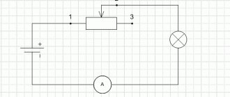
DRL connection diagram without relay
This is the simplest DRL connection diagram, but also the most incorrect. I'll describe it a little. With this connection scheme, you supply voltage to the DRLs from the main power circuit of the car. The main power circuit is activated when the key is turned in the ignition switch. Obviously, your DRLs will always work as long as the key is turned in the ignition, no matter what lighting you use. You have no way to turn off the DRLs until you remove the key from the ignition.
As you already know, the use of DRLs in conjunction with other lighting devices is prohibited. I do not recommend connecting DRLs using this scheme.
Additional relay block. BRP 8/13 – DRIVE2
Another custom block. But I decided to move away from boards in favor of wall mounting.
The order was for 4 active relays + 2 spare ones. I decided to pack it in a 150/100/70mm box with IP55 protection. I figured out the location and decided to not waste the space - add 2 more backup relays.
Description:
Power input - M6 (stainless steel). Power wires - 2.5mm^2. Power wires of the open contact of the relay - 1.5mm^2. Control wires - 1mm^2. 6 blocks for 4-pin relays. 2 blocks for 5-pin relays (with open contact). 1,3,4,5 relays have double output. You can connect to 1 or 2 fuses at once. Fuse block for 13 fuses (12 pcs for consumers and 1 pc protection for control relay windings). Housing 150/100/70mm IP55 Females, heat shrink and power tip (included). Relays and fuses (included).
Some photos:
Wall-mounted installation.
Installation on block walls.
Control block. 8 contacts.
Safety block (contacts modified to prevent biting).
Fuses are in place. Everything fits tightly and is easy to remove.
Power input M6 stainless steel and lug for 16mm^2 wire.
Connection diagram.
3 years Tags: brp, relay block, fuse block, relay and fuse block, additional relay block
Likes 129 Shares: Subscribe to author
www.drive2.ru
DRL connection diagram via 4-pin relay
To connect the DRL according to this scheme, you, as in the previous case, will need a 4-pin relay. Moreover, the connection diagram is absolutely identical to the previous case, only instead of the control signal from the oil pressure sensor, we will use a button in the car interior. Your DRLs will only turn on when you press a button in the cabin.
You can add a little automation to this scheme. In order for the DRLs to go off when the engine is stopped, you can send a signal to the button from the fuel pump, or from the same oil pressure sensor. This scheme already has the right to life, because you can control the DRL operation depending on your driving conditions.
The only downside is that you need to manually turn off the DRLs (press a button in the cabin) when you turn on the low beam headlights, and also manually turn on the DRLs when driving during daylight hours.
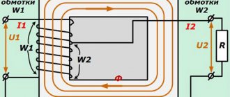
What's hidden inside the relay? — logbook Lada 2106 Adam 1988 on DRIVE2
Hello Dear Friends!
The article was written mainly for my Friend - Anton Yashurin (YaToshker-89), who asked me to explain what and where to connect to the classic and most common 4 or 5-pin automotive relay, as well as help learn to understand which relay is normally open and which is normally closed.
The fact is that it is possible to answer this question in an intelligent way only with the use of extensive graphic material, which is not possible within the framework of personal correspondence, therefore, forgive me, my friend, for taking “quarrels from the public”, and answering a personal question within the framework of a public post - It’s just more clear this way))) Also, I think that those of my Friends who are still a little confused about the architecture of this device (relay) will find a lot of useful things for themselves.
In fact, the relay does not contain anything complicated, and in order to learn how to connect it correctly in each new case, you just need to “get into” the principles of its operation once.
So, let's begin:
4 and 5 contact relays - top view.
4 and 5 contact relays - bottom view.
These are some of the most common domestically produced automotive relays - the cheapest and easiest to install. They are just classic electromechanical relays, consisting of an electromagnet and silver contacts controlled by it and nothing more! Already from the top, on the cover, we can see a lot of the most useful information characterizing these relays, namely: the name of the relay, its circuit diagram, the numbering of the terminals (legs, hereinafter referred to as legs), the maximum current through the contacts that they can switch (interrupt and again unite). In a 4-pin relay it is 30 A (relay 75.3777-10), and in a 5-pin relay (relay 75.3777), note, 30 and 20 A - the currents on different contacts are different, i.e. consumers cannot take more than 20 A from leg 88, and more than 30 A from leg 87. Note also that the circuit located on the top of the relay absolutely accurately reproduces the location and numbering of the legs from below (as if we were looking at them through the relay) . This allows you to connect the relay without disassembling it, but only looking at the diagram from above))) From the same diagram we can easily see what our relay is - normally closed or normally open - just look at the position of the key on the diagram. For example, on relay 75.3777, the key connects the contacts and supplies current to leg 88 from leg 30 constantly, which means that the contacts of leg 88 are normally (meaning without supplying current to the control windings) closed. The contacts of leg 87 are, on the contrary, normally open. When current is applied to the relay coil, the position will change to the opposite. Those. a five-pin relay is both normally closed and normally open at the same time - depending on which legs and contacts we use, looking at the diagram (this is where its greater versatility lies). Inside, a five-pin relay looks like this (the red curved line indicates how current flows from leg 30 through the relay mechanisms and flows down either to leg 88 or 87 (depending on the position of the contacts)) (note that the legs and contacts are connected crosswise ):
Inside of a five-pin relay.
The remaining relay legs are 86 and 85 (although this numbering is unchanged for all Russian and Soviet-made automotive relays), these are the legs connected to the control winding of the relay. It is through these legs that the control current must pass: arrive at one and flow to ground from the other (polarity is not important). On some relays these legs even come in a different color:
For example, this relay has legs connected to the winding that are gray, and the remaining legs connected to the contacts are golden.
The four-contact relay 75.3777-10 shown in the first photo has only one contact pair and, as you probably already guessed from the diagram, it is normally open. Shall we check?
The way it is. And instead of a second contact pair, there is only a plastic rudiment - a travel limiter.
This rudimentary limiter in some relay models can also be metal. Also, for example, this model has a real return spring, and not a weak petal, as in the previous example.
However, I advise you not to rely too much on the diagram located on top, since the relay could be incorrectly assembled by someone and, therefore, everything could go down the drain (((To be on the safe side, always look under the relay cover before installing it so that I would like to understand everything again, especially since opening the relay cover is very simple:
Just pick up a mustache)))
For all types of automotive four- and five-pin relays there is a universal plastic block with 5 female terminals:
I recommend using this one - it’s very convenient. The terminals in it are arranged depending on the selected connection type, example:
Some photos:
Now you know more about automotive relays. But this is a description of only one type of them. There is also a huge mass of other varieties of these devices - even more interesting in their design - discover them for yourself - it’s very interesting)))
With best wishes - Kolkhoznik)))
www.drive2.ru
Connection diagram for DRL via 5-pin relay
This scheme is the most correct and automated; I recommend connecting the DRLs according to this scheme. This circuit uses a 5-pin relay. Let's talk a little about the operating principle of a 5-pin relay. The 5-pin relay has 2 power outputs. In the normal state, the first of the power terminals is closed, the second is open. After applying a control signal to the relay, the first output will become open and the second will become closed. This seems complicated, but let's look at an example and everything will become clear.
- Contacts 85 and 86 are control contacts. Depending on whether there is voltage on them or not, contacts 87 or 87A close;
- Contact 30 – power supply contact of the relay. It is to this that voltage must be supplied to power consumers;
- Contacts 87 and 87A – contacts for connecting consumers.
Let me give you an example. There is no voltage on contacts 85 and 86; power through the relay goes to the consumer at contact 87A. There is voltage on pins 85 and 86, the relay switches power to the consumer on pin 87.
- We supply power to the DRLs and headlights through pin 30. For greater automation, take power from the main circuit of the car, which turns on when the ignition is turned on;
- We connect DRLs to contact 87A, which will always be on;
- We connect the headlights to pin 87, which will turn on only when the DRLs are turned off;
- To contacts 85 or 86 (it doesn’t matter), we apply a control signal from the headlights button in the cabin;
- We connect the remaining contact 85 or 86 to the car body.
With this connection, either the DRLs or the headlights may work. When the car is turned off, both the DRLs and headlights are turned off.
- Price: $1.66
- Go to the store
In today's review, I will share with you my impressions of a 5-pin automotive relay purchased on eBay, and also show one of the possible options for its use.
The relay was ordered almost simultaneously with the DRL kit that I talked about a few days ago. For what? Because when using a standard connection, when turning on the side lights or low/high beams, the DRLs still continued to light up. I didn’t find anything good in this, and therefore I began to think about automating their shutdown when turning on the headlights or low beam. The simplest and most logical option seemed to me to be using a relay.
By the way, this is one of the few purchases that I went to the local auto parts store before making. Imagine my surprise when I saw the price in the VAZ store: relay - 5 rubles (about $2.5), a block for it - 2.5 rubles ($1). Total, $3.5 per set offline with us without waiting, versus $1.66 with them. The choice is obvious