Differential protection is used
- power transformers (you can read about differential protection of transformers here);
- generators;
- busbars;
- cable lines;
- air lines.
Due to its reliability and speed, it is one of the main ones for the above devices.
For an interesting video about the operation of transformer differential protection, see the video below:
Operating principle of differential protection
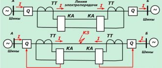
The basis of the operating principle of any differential protection is the control of currents at the beginning and end of the protected section of the electrical circuit. Current transformers are used for this. When located within the same switchgear, they are connected to the protection device directly using cables. If the boundaries of the protected area are located at a large distance from each other, which is typical for cable or overhead lines, two half-sets of protection are used, connected to each other by an auxiliary cable line.
If these currents at the beginning and end of the protected section are equal to each other and directed in one direction, no operation occurs. This happens when rated load currents flow or during a short circuit outside the protected area (external short circuit currents).
But if the damage occurs in an area controlled by the protection, the power of the electrical network flows to the short circuit point. With one-way power supply (for transformers or generators), more current flows from the source towards the protected electrical device than is given to the consumer. With two-way (on a cable or overhead line connecting networks with independent power sources), the currents at both ends of the line are oriented to the point of damage.
A reason is created for the protection to operate, which gives the command to turn off the object simultaneously from all sides.
Depending on the characteristics of the protected object, appropriate differential relays are selected for the implementation of devices. Let's consider their features.
Details about the operating principle of the differential. protection, watch the video:
Differential relay (residual current device). What it is?
________________________________________________________________________________________A residual current device, an RCD, a differential relay, a differential circuit breaker - all this is one and the same structural device.
A differential relay or RCD is designed to protect a person from electric shock when directly touching one of the live parts (bare wire, body of an electrical device that has come under voltage, etc.). and is capable of protecting against fires and fires that occur at facilities due to possible damage to insulation, faulty wiring and electrical equipment. The RCD (diffrel) detects the current imbalance that has arisen in the wiring due to the occurrence of leakage current and turns off the power supply within 10-20 ms (mechanical inertia of the device).
| ______________________________________________________________________________ According to the VNIIPO of the Ministry of Internal Affairs of the Russian Federation, more than a third of all fires occur due to the ignition of electrical wiring as a result of its malfunction, incorrect selection of the wire cross-section or defects in the insulation as a result of aging of the wire and as a result of heating of the conductors along the entire length, sparking, etc. In case of insulation defects, short circuits to ground, current leakage to ground, the RCD, reacting to the leakage current, disconnects the electrical installation from the power source, thereby preventing unacceptable heating of the conductors, sparking, arcing and possible subsequent fire. Differential relay (RCD) is an effective means of protecting human life and fire protection. A residual current device that responds to differential current, along with an overcurrent protection device, refers to an additional type of human protection from injury when a person is directly or indirectly exposed to voltage. A residual current device (RCD) monitors current leakage from the circuit (the human body acts as a conductor) and provides automatic shutdown of the power supply to the emergency power supply section within a time not exceeding 20 ms (+40...-60%) from the moment the leak occurs. |
Differential relays are available in two types: AC and A. Type AC reacts to leakage of alternating (sinusoidal) currents. But in electrical circuits that supply equipment that contains rectifiers or controlled thyristors, in the event of an insulation breakdown, leakage of not only alternating current, but also direct (pulsating) current is possible. RCD type AC does not respond to this. Type A differential relay is designed for such cases. In the operating instructions for some household appliances, for example, washing machines and refrigerators, you can find instructions about the need to install this particular type of relay.
Differential circuit breaker - the name that arose in everyday life (difavtomat) is assigned to a residual current device with built-in protection against overcurrents (short circuit currents and overload currents). It triggers in both cases - both in case of current leakage to the ground and in case of short circuits or overload.
The differential relay conducts a comparative vector analysis of the phase-zero current. If the vector sum is not zero, a signal is sent to the device shutdown mechanism.
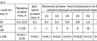
The selection of a differential relay is carried out primarily based on the leakage current: 10 mA - for wet domestic premises (bathroom), 30 mA - for premises where there is a possibility of a person getting under voltage, 100 or 300 mA - used as fire protection and installed at the input one for the whole house (building). A differential relay should always be used with a circuit breaker to protect against short circuits or overload currents. The differential current rating of the differential relay must be greater than the circuit breaker on that line. For example, if the circuit breaker is 40 amperes, then the RCD is selected at 63A. Thus, the rated current of the RCD does not mean that it will turn off at 40A, but it means that it will burn out at 60A.
How many diffusers do you need to install? To ensure safety from electric shock, one for the entire apartment is enough. Of course, it is better if, in the event of any problem with electrical wiring or electrical appliances, only the corresponding line is turned off, and the entire apartment is not de-energized, so it is better to install the RCD separately along the lines (for example, in the children's room, on the line of sockets, in the bathroom).
When installing difrel in apartments or houses with electrical wiring, the question will definitely arise about frequent, if not constant operation of the RCD. This means only one thing: the wiring has long not met the standards for core insulation. Well, now we need to change the wiring too. Assess what is more important to you - the threat of electric shock, fire from faulty electrical wiring, or carrying out another repair? By the way, if after replacing the wire and laying it in the walls, the RCD is triggered - all the questions are not for the diffril, but for the builders. What wire was laid and how? Many electricians do not even mention to the owner the existence of such a controller, so ask for the installation of an RCD - it will not only save you from fires and electric shocks, but will also detect damage to the insulation on the wires.
In connection with what has been stated above and according to the Rules, the value of the disconnecting differential current can be selected in accordance with the type of network:
— sockets — 30 mA;
- sockets in the nursery and bathroom - 10 mA;
— the lighting network may not be protected or a device with a rating of 30 mA may be installed;
- sockets for powering electrical equipment operating on the ground - only 10 mA.
- at the entrance to a house or apartment, to prevent fire - 100 or 300 mA.
Electrical engineering
Differential protection on the RNT relay
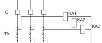
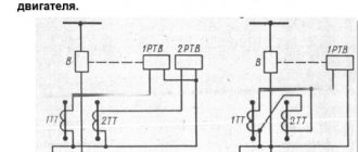
The relay consists of two elements combined into one housing. This is a fast-saturating transformer, which has three rods with windings, and an output current relay, which is an executive element.
The relay is connected to the terminals of the secondary winding located on the outermost rod of the transformer. Two, and sometimes three primary windings are located on the middle rod and are connected to current transformers. There are also additional short-circuited windings designed to dampen the aperiodic component.
The relay is configured by switching the number of turns of the primary windings in order to achieve equality of magnetic fluxes in the magnetic circuit. Also, by changing the resistance of resistors in the output and compensating circuits, the required braking during transient processes is set, as well as the operating current of the output relay.
RNT is used mainly for operation as part of relay protection and automation equipment for power transformers. At the first moment of connection to the network, powerful magnetizing currents arise in their core. They quickly attenuate, but at the same time a precedent is created for the operation of the protection: after all, the power for magnetization is consumed from the source and remains in the transformer.
The RNT device allows you to detune from magnetizing currents . When there is a sudden surge of current, the transformer core quickly becomes magnetized and the relay stops responding to such a disturbance.
But at the same time, with powerful through relays, they can operate falsely due to unbalance currents. The DZT relay does not have this drawback.
A useful tutorial on calculating differential protection for transformers can be viewed and downloaded here. (size - 5.5MB). Author M.A. Alexandrov - St. Petersburg, PEIPK.
Differential relays D-4V and RDZ-504
Purpose and technical data. Differential relays are used to protect against short-circuit currents in the power circuits of traction motors and auxiliary machines of an electric locomotive in traction mode.
The relay blocking contacts protecting the power circuit of the traction motors are included in the holding coil circuit of the high-speed switch BVP-5; The relay blocking contacts protecting the power circuit of auxiliary machines are included in the coil circuit of the high-speed switch BVE-< TsNII. On electric locomotives VLYU up to No. 1587 built by TEVZ, differential relays D-4V are installed, and starting from No. 1587, relays RDZ-504 are installed in the power circuit of traction motors instead. The technical data of the relay is as follows:
d-4v rdz-504
Rated voltage of the power circuit, A 3000 3000
Rated voltage of the switching coil and contacts, V…… 50 50
Magnetomotive force (setpoint), A, at rated voltage on a coil with an additional resistor of 300 Ohm resistance………. 100 100-ao
Own response time (at a current rise rate of over 105 A/s), s, no more……… 0.0065 0.0065
Coil resistance at a temperature of 20° C, Ohm………6.7-7.5 3.6
The longest duration of activation of the coil without an additional resistor at a voltage of 55 V, s……. 60 40
Rated current of contacts, A. . 5 5
Number of normally open contacts…. eleven
Contact failure, mm……2-3 1.5-2
Contact gap, mm...... - 4-5
Working gap at the center of the pole with the armature open, mm......10-12 5±0.5
Area of contact of the armature to the core of the magnetic circuit, %...... - 80
The coil must ensure restoration of the relay by forcing at a current, A, no more than 4.4
AC voltage frequency
50 Hz to test the insulation of the coil against the blocking or the nearest mounting bolt for 1 min, V. 1500 1500 Weight, kg………. 17 6
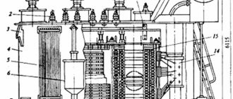
Design and principle of operation. Differential relay D-4V (Fig. 128) consists of a laminated magnetic circuit 8 (fastened by two side brackets), a coil 6, an additional resistor 7, an armature 5 and blocking contacts 4. In the upper part of the magnetic circuit, an insulating panel 1 is fixed to the protrusions of the side brackets. A coil is placed on one of the protruding magnetic core packages, and an armature with an adjusting spring 2 and a locking contact is installed on the other. A stand with a limiting strip 3 is attached to the middle of the insulating panel. A magnetic shunt package made of electrical steel is fixed between the brackets. An additional resistor, blocking contacts and output clamps are attached to the insulating panel. The cables of the beginning and end of the circuit protected by the differential relay are passed through the window of the magnetic circuit.
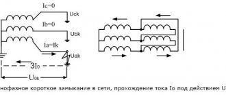
The relay turns on when a voltage of 50 V is applied to the coils, after which a resistor is introduced into its circuit. The direction of the magnetic flux generated by the coil is shown in Fig. 129 is a solid line, and the magnetic flux arising from the passage of the unbalance current of power cables stretched through the window of the magnetic system is dashed. In the working gap a, the indicated flows are directed counter.
In the absence of a short circuit (short circuit) in the area protected by the differential relay, the magnetic flux created by the currents flowing through the power cables is zero. Under the influence of the magnetic flux of the coil, the armature is attracted and the blocking contacts are closed.
When does short circuit occur? an unbalance current occurs in the circuit protected by the differential relay. When the unbalance current reaches a value equal to the relay setting current, the magnetic flux becomes such that the force from the resulting flux in the working gap area becomes less than the force of the adjusting spring, and the relay armature disappears. In this case, the blocking contacts open and break the power supply circuit of the holding coil of the BVP-5 or BVE-TsNII switch. The latter turn off and break the short-circuit current.
The magnetic shunt serves to ensure that during a short circuit. there was no reverse switching of the armature, since the short-circuit current does not stop immediately. When the armature falls off, the short-circuit current continues for some time. flows through the power cables, and the magnetic flux from this current tends to attract the armature again. In the presence of a magnetic shunt, the flux from the unbalance current will mainly flow through it, since the conductivity of this section of the magnetic circuit AB is much greater than the conductivity of the air gap a - 10 ~ -12 mm. The diagram for connecting the relay to the power circuit is shown in Fig. 130.
Relay D-4V of the power circuit of traction motors is adjusted to an unbalance current of 100 A with one wire inserted into the frame. Relay D-4V of the power circuit of auxiliary machines is regulated for an unbalance current of no more than 50 L with two turns of wire inserted into the frame.
At the stand, the relay is adjusted as follows. A wire is inserted into the magnetic circuit frame, and voltage is applied to the coil. The armature must be attracted at a voltage across the coil (without an additional resistor) of 50 V and reliably held at 40 V when an additional resistor installed on the relay is connected to the coil circuit. A current equal to the unbalance current is passed through the wire inserted into the frame. Since the relay is polarized, during testing and installation the specified connection polarity should be strictly adhered to. The armature should fall off when the unbalance current is adjusted by the relay, and the voltage on the coil is 50 V with the additional resistor turned on. The relay setting current is adjusted by changing the spring tension. If the relay armature does not fall off when current passes through the wire, you need to change the polarity of the relay coil.
Checking the relay adjustment on an electric locomotive is performed as follows. The differential relay of the main circuit is adjusted to an unbalance current of no more than 100 A. Before testing, it is necessary to make sure that opening the relay contacts manually causes the high-speed switch BVP-5 to turn off. For testing, it is necessary to artificially create a short circuit. in front of the traction motor, for which a jumper is placed between the engine switch blade and the ground.
To check the polarity of the relay when the BVP-5 switch is on and the electric locomotive is braked, install the main handle of the controller in the 1st, 2nd and 3rd positions. If the relay blocking does not open and the BVP-5 switch does not turn off, then change the polarity of the relay switch. The relay setting is checked with the BVP-5 switch on and the braked electric locomotive in the 1st position. If the relay contacts do not open and the BVP-5 does not turn off, then increase the tension of the relay adjusting spring.
Differential relays of auxiliary circuits regulate the unbalance current to no more than 50 A. Before testing, it is necessary to make sure that opening the relay contacts manually causes the high-speed switch BVE-TsNII to turn off. For testing, a short circuit is created. after the fan on the fan switch or in the starting resistor of the second fan at terminal P68 (see tab, Fig. 188). Then the pantograph is raised and the fans are turned on at low speed. The relay's latching contacts open and the switch turns off. If this does not happen, then check the polarity of the relay or increase the spring tension. The spring tension, measured along the axis of the core, must be at least 6.5 kgf. When putting an electric locomotive into operation, technical maintenance of TO-3 and routine repairs, check the correctness of switching on and adjusting the relay for unbalance current; restoring the relay by forcing it at a voltage of 35 V in the control circuit,
Differential relay RDZ-504 (Fig. 131, 132) consists of a laminated magnetic circuit 8, a coil 5, an armature 4, an adjusting spring 6, a blocking 2 and an additional resistor consisting of two parallel-connected resistors 7 of type PEV-15-390 Ohm. The magnetic core, blocking and additional resistor are installed on panel 1. The relay is covered with casing 3.
The operating principle, adjustment and adjustment check of the differential protection relay RDZ-504 are similar to the D-4V relay.
After checking the relay setting on an electric locomotive, the tension of the adjusting spring, measured along the axis of the magnetic core, should be less than 7 kgf, and the force reserve in the pulled position of the armature and a voltage of 40 V should be at least 0.5 kgf.
⇐ | Boxing sensor DB-018 | | Electric locomotive VL10 | | Speed relay RKO-28 | ⇒