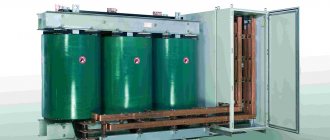
To measure quantities with large values, current transformers are used. For this purpose, the primary winding of the device is connected in series to a circuit with alternating current, the value of which must be measured. The secondary winding is connected to measuring instruments. There is a certain proportion between the currents in the primary and secondary windings. All transformers of this type are highly accurate. Their design includes two or more secondary windings, to which protective devices, measuring instruments and metering devices are connected.
What is a current transformer?
Current transformers are devices in which the secondary current used for measurements is in proportion to the primary current coming from the electrical network.
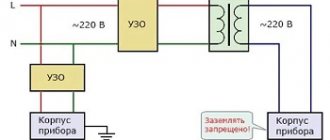
The primary winding is connected to the circuit in series with the current conductor. The secondary winding is connected to any load in the form of measuring instruments and various relays. A proportional relationship arises between the currents of both windings, corresponding to the number of turns. In high voltage transformer devices, insulation between the windings is carried out based on the full operating voltage. As a rule, one end of the secondary winding is grounded, so the winding and ground potentials will be approximately the same.
All current transformers are designed to perform two main functions: measurement and protection. Some devices may combine both functions.
- Instrument transformers transmit the received information to connected measuring instruments. They are installed in high voltage circuits in which it is impossible to directly connect measuring instruments. Therefore, ammeters, meters, current windings of wattmeters and other metering devices are connected only to the secondary winding of the transformer. As a result, the transformer converts alternating current, even a very high value, into alternating current with indicators that are most acceptable for the use of conventional measuring instruments. At the same time, the isolation of measuring instruments from high-voltage circuits is ensured, and the electrical safety of operating personnel is increased.
- Protective transformer devices primarily transmit the received measurement information to control and protection devices. With the help of protective transformers, alternating current of any value is converted into alternating current with the most suitable value, providing power to relay protection devices. At the same time, relays that are accessible to personnel are isolated from high voltage circuits.
Purpose of transformers
Current transformers belong to the category of special auxiliary devices used in conjunction with various measuring devices and relays in alternating current circuits. The main function of such transformers is to convert any current value to values that are most convenient for measurements, providing power to disconnecting devices and relay windings. Due to the insulation of the devices, service personnel are reliably protected from high voltage electric shock.
Measuring current transformers are designed for electrical circuits with high voltage, when there is no possibility of direct connection of measuring instruments. Their main purpose is to transmit received data on electric current to measuring devices connected to the secondary winding.
An important function of transformers is to control the state of the electric current in the circuit to which they are connected. During connection to the power relay, constant checks of the networks are performed, the presence and condition of grounding. When the current reaches an emergency value, protection is activated, turning off all equipment in use.
General requirements
The energy meter is designed specifically to determine the amount of power consumed by electrical devices and to simplify calculations of the load on the outlet. Learning how to use it happens quickly. After all, the instructions for use help.
Principle of operation
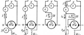
The operating principle of current transformers is based on the law of electromagnetic induction. Voltage from the external network is supplied to the power primary winding with a certain number of turns and overcomes its total resistance. This leads to the appearance of a magnetic flux around the coil, captured by the magnetic circuit. This magnetic flux is located perpendicular to the direction of the current. Due to this, losses of electric current during the conversion process will be minimal.
When the turns of the secondary winding, located perpendicularly, intersect, the electromotive force is activated by the magnetic flux. Under the influence of the EMF, a current appears that is forced to overcome the total resistance of the coil and the output load. At the same time, a voltage drop is observed at the output of the secondary winding.
Classification of current transformers
All current transformers can be classified depending on their features and technical characteristics:
- By appointment. Devices can be measuring, protective or intermediate. The latter option is used when connecting measuring instruments to current circuits of relay protection and other similar circuits. In addition, there are laboratory current transformers that are characterized by high accuracy and a variety of transformation ratios.
- By installation type. There are transformer devices for external and internal installation, overhead and portable. Some types of devices can be built into cars, electrical devices and other equipment.
- According to the design of the primary winding. Devices are divided into single-turn or rod, multi-turn or coil, and also bus, for example, TSh-0.66.
- Internal and external installation of transformers involves pass-through and support methods for installing these devices.
- Transformer insulation can be dry, using bakelite, porcelain, and other materials. In addition, conventional and capacitor paper-oil insulation is used. Some designs use compound filling.
- Depending on the number of transformation stages, devices can be one- or two-stage, that is, cascade.
- The rated operating voltage of transformers can be up to 1000 V or more than 1000 V.
Using a Transition Test Box
Installation of the device:
- mounting a reference metering device into the metering unit;
- orientation of current in an electrical circuit through current loops;
- switching off current circuits;
- connection of phase conductors to the metering device.
The test adapter box (TCB) is designed to “short-circuit” (bypass) current circuits.
Parameters and characteristics
Each current transformer has individual parameters and technical characteristics that determine the scope of application of these devices.
Rated current
Allows the device to operate for a long time without overheating. Such transformers have a significant heating reserve, and normal operation is possible with overloads of up to 20%.
Rated voltage
Its value should ensure normal operation of the transformer. It is this indicator that affects the quality of insulation between the windings, one of which is at high voltage and the other is grounded.
Transformation ratio
It is the ratio between the currents in the primary and secondary windings and is determined by a special formula. Its actual value will differ from the nominal value due to certain losses during the transformation process.
Current error
Occurs in a transformer under the influence of magnetizing current. The absolute value of the primary and secondary current differs by exactly this amount. The magnetizing current leads to the creation of a magnetic flux in the core. As it increases, the current error of the transformer also increases.
Rated load
Determines the normal operation of the device in its accuracy class. It is measured in Ohms and in some cases can be replaced by such a concept as rated power. The current value is strictly standardized, so the power value of the transformer completely depends only on the load.
Nominal limiting factor
It represents the multiple of the primary current to its rated value. The error of this multiplicity can reach up to 10%. During calculations, the load itself and its power factors must be rated.
Maximum secondary current ratio
Presented as the ratio of the maximum secondary current and its rated value when the effective secondary load is rated. The maximum multiplicity is related to the degree of saturation of the magnetic circuit, at which the primary current continues to increase, but the value of the secondary current does not change.
Connection diagrams for a three-phase electricity meter
Only a correctly connected meter correctly determines and controls the amount of current used. Therefore, the device must be connected correctly. The mounting scheme is determined by the type.
Semi-indirect
It is mounted into the network with a TT. Therefore, it is possible to connect to networks with high powers. Up to 60 kW is allowed. Using this accounting method, to establish expenses, it is worth multiplying the difference in indicators by a certain transformation value.
Ten-wire
She is very popular. This is what experts recommend installing now. After all, it has a number of advantages. They do not have a galvanic connection between the current circuits of the meter and voltage circuits. Therefore, connecting it is much safer. And thanks to it, it is more convenient to carry out manipulations.
There is no need to turn off the settings when changing the meter or when carrying out various manipulations. It is distinguished by its correctness. After all, information collection for all phases occurs independently. If there is a violation of the metering circuits in any of the phases, the functioning of the metering in other phases continues.
The 3-phase meter must be installed carefully for proper functioning. Particular attention should be paid to labeling. The 10-wire requires more wires than other circuits.
The 10-wire has a drawback: significant conductor consumption for assembling secondary metering circuits.
Seven-wire
It got its name because of the number of wires used during connection. It is considered outdated, although it can be found.
The transformer meter must have a contact panel. If it is not there, then there must be a block. They serve as a connection conductor. They are located in the middle of the electrical cord and the meter.
With combined chains
During this method, voltage circuits are connected to current circuits by installing connections on the CT.
Star
Nuances of the method:
- All types of short circuits conduct current individually. And the guarantee of safety and operation created in this way responds to any short circuit;
- the current in the relay belongs to the phase current;
- the zero-sequence current that does not pass through the relay will not go beyond the edges of the CT triangle.
Incomplete
It is worth installing an incomplete star only in networks where there are zero isolated points. They protect against phase-to-phase short circuits. It responds only to isolated occurrences of a single-phase short circuit.
Full
If there is a solidly grounded neutral, then you need to connect the CT to three phases.
Indirect
If devices in the network that use electrical energy waste it more than the rated value of the current passing through the meter, then it is worth installing separating CTs. They are connected to the break in the power current-carrying cords.
With two TTs
In 380 V networks, when creating metering systems for power consumption of more than 60 kW, a 100 A electric meter is installed using an indirect three-phase connection scheme via a CT. This helps to measure larger power used by metering devices for smaller power using the device's conversion factor.
Mercury 230
Assembly diagrams for a Mercury meter using CTs are complex. The connector should not forget about responsibility in the process. It is usually used on a 380 volt network.
To zero sequence current filter
If there is a single-phase and two-phase ground fault, then current volumes in the relay are detected.