– one of the most common devices used to automate processes in electrical engineering. In fact, it is an automatic switch that connects or disconnects electrical circuits when the set values are reached or under external influence. Relays are used in industry to automate technological processes, in household appliances that are found in every home, such as refrigerators and washing machines, to protect the network from too high or too low current parameters. Selecting the right device simplifies the classification of relays according to various criteria.
General description of the design
The concept of “relay” unites a whole family of devices of different designs. But in general, a relay consists of three main functional elements:
- Perceiver.
This is the primary element that perceives the controlled quantity and converts it into another physical quantity. - Intermediate.
Compares the received value with the specified parameter. If this value is higher or lower than the specified parameter, then the primary effect is transmitted to the actuator. - Executive.
This element transmits the action to circuits controlled by relays. As a result of such an impact, the following may occur: opening or connecting the controlled circuit, switching current parameters.
The design and operating principle of the primary element depend on what purpose the relay has and what physical quantity (current, voltage, light, heat, etc.) it is set to.
RU device
The relay design contains the following elements:
- drive manually raised to working position;
- a measuring element that continuously monitors the formation of factors leading to operation;
- an actuator, which, after receiving a signal from the measuring part, is instantly activated;
- electromagnet;
- anchor;
- flag or other signaling device;
- bridge;
- contact plates;
- return button and spring.
Main characteristics of the relay
Regardless of the type and principle of operation of the relay, there are several parameters that you pay attention to when choosing this device:
- Response time is the time interval between the arrival of the control signal and the effect on the controlled circuits.
- Switched power is the permissible power of the electrical circuit or electrical installation that the relay will control.
- The setpoint is usually an adjustable parameter that determines the value of the incoming parameter (current, voltage, frequency, pressure, temperature) at which the relay operates.
Types of relays: contact and non-contact
According to the design of the executive component, relays are divided into contact and non-contact.
Contact
They influence the controlled circuit using electrical contacts. Opening or closing them completely disconnects or closes the electrical circuit. The following materials are used to make contacts: copper, silver, tungsten. Number of contacts – up to 10 pieces. Four- and five-pin relays are used in automobile electrical circuits to switch and switch circuits.
Contactless
Such relays act on the controlled circuit by changing the electrical parameters of the output electrical circuits - capacitance, resistance, inductance, current or voltage.
Literature
- Petrakov V. AXICOM: a new generation of telecommunications and signal relays. Components and Technologies No. 8, 2002;
- Melashchenko A. History of the creation and development of relays. Electronic components No. 9, 2004;
- Presentation. AXICOM. Telecom-, Signal and RF Relays. IM Relays. Tyco Electronics, 2008;
- Automotive, General Purpose and Signal Relays. Definitions. Tyco Electronics, 2012;
- Presentation. Telecom – & Signal Relays. Tyco Electronics, 2012;
- Documentation www.te.com.
Obtaining technical information, ordering samples, ordering and delivery.
•••
Classification of relays by switching method
Primary
These devices are connected directly to the circuit of the element they are intended to protect. Their advantages are that instrument transformers, operating current sources, and control cables are not required.
Secondary
Connected to a circuit using secondary transformers. This is the most common type of relay. Their advantages are insulation from high voltage, the ability to locate the device in a place convenient for maintenance. Secondary relays are available as standard. They are designed for a current of 5 (1) A and a voltage of 100 V and can be installed in any electrical circuit, regardless of their current and voltage.
Possible connection errors
- A common mistake is to use a certain type of relay in the wrong circuit conditions. Most often, such an error leads to failure of the device at the first operation.
- Another common mistake is the operation of the relay in climatic conditions that do not correspond to the design of the device. The device will operate for a short time.
- Connecting an SPD to a single-phase or three-phase network, in the panel (diagram)
- Marking of wires, cables and cords by color (GOST)
- Move the outlet to another location with your own hands
Types of relays by purpose
According to their purpose, these devices are of three types - control, protection, alarm.
Control relay
These relays are primary. Mounted directly into the electrical circuit. Their role is to turn on and off individual elements of the circuit. They can be used independently or as components of low-voltage complete devices - boxes, panels, cabinets.
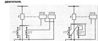
Protection relay
Perform the functions of turning on, turning off and protecting devices with thermal contacts - electric motors, fans. When the temperature is exceeded, the thermal contacts open. The equipment can resume operation only after the thermal contacts have cooled to the set temperature.
Alarms
Such relays are installed in security systems of vehicles, enterprises, and local areas. They are used to generate a signal when a set value of a parameter that is under control is reached (current, voltage, frequency, pressure, temperature, acoustic parameters and others).
Types of electromechanical relays
The most common type of electrical relay is electromechanical. These include: electromagnetic, induction, electrothermal devices.
Electromagnetic
One type of electrical relay is electromagnetic. The design of this device includes: a winding with a steel core, a group of movable contacts that make and break a controlled electrical circuit. Let's consider the principle of their operation:
- A control current is supplied to the core coil.
- A magnetic field is created in the core under the influence of electric current, attracting the contact group.
- Depending on the type of relay, the contacts close or open the electrical circuit.
A variety of electromagnetic relays are polarized, which differ from neutral ones in their ability to respond to the polarity of the control signal. The opening or closing of the contacts depends on the polarity of the electromagnet connection. They have higher sensitivity compared to neutral relays. Such devices can only be used in DC circuits.
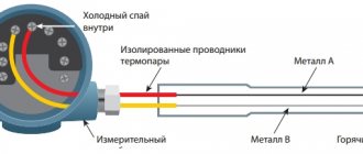
Electrothermal (thermal)
Thermal relays are a complex of bimetallic plates, for the manufacture of which metals with different expansion coefficients when heated are used. Such relays can be used as protective devices: when the temperature set by the regulator is exceeded, the contacts are disconnected and the flow of current to the consumer is stopped.
Typically, thermal relays are used in household single- and three-phase networks when connecting electric motors. When the load on the engine increases above a set value, the bimetallic relay heats up, which, when a certain temperature is reached, opens the electrical circuit. The engine stops running. After the bimetallic plates cool, the circuit closes and the engine resumes operation. Thermal devices can be equipped with a wheel that adjusts the engine shutdown temperature and a forced start button.
There is a type of thermal relay in which bimetallic plates are replaced with a low-melting alloy. They operate almost instantly - when a certain temperature is reached, the metal melts and the circuit opens. The principle of operation of such devices is similar to the principle of operation of fuses. After operation, such a relay, installed directly on the equipment as a last resort against burnout, must be replaced.
Induction
The operating principle of these devices is based on the interaction between alternating magnetic fluxes and currents that form alternating magnetic fluxes. Induction devices are designed for use in alternating current circuits only. There are three types of induction relays - with a frame, a disk, and a cylindrical rotor (“glass”). These devices are widely in demand in relay protection and automation systems.
Connection diagrams
Tip No. 1: For almost every model of indicating relay, the manufacturer has developed a connection diagram, following which you can achieve uninterrupted and reliable operation.
Considering the connection diagrams, we can highlight several features of connecting each relay model:
- the circuit provides for a pair of closing contacts without self-resetting;
- circuit with a pair of closing contacts without self-resetting and one self-returning contactor;
- two non-self-resetting contacts: one is normally closed, the other is normally closed;
- circuit with make and break contacts without self-return and one self-returning contactor;
- a pair of normally open contacts without self-resetting;
- circuit with a pair of breakers without self-resetting and one self-resetting contactor.
Other types of electrical relays
Solid State
These electronic devices are compact and durable due to the absence of rubbing mechanical parts. The mechanical work here is performed by semiconductor elements - bipolar and MOS transistors, thyristors, triacs. Compared to solid-state ones, they have the following advantages:
- Low noise level during operation.
- Very high mean time between failures, which is 100 times or more greater than the service life of electromagnetic devices.
- The response speed is a fraction of a millisecond; for electromagnetic ones it is 50 ms - 1 s.
- Power consumption is 95% lower.
However, solid-state relays have not only advantages, but also disadvantages. One of them is poor resistance to surge voltages, which are practically not dangerous for electromagnetic relays. When using solid-state relays, it is necessary to provide a circuit design that limits these pulses. There are also disadvantages - heating during operation, the presence of leakage currents, leading to the presence of voltage on the phase wire even when the relay is turned off.
Solid-state relays are used in temperature control systems, in which heating elements are used as heaters, in industrial automation, telemetry, equipment mechanisms used in the metallurgical and chemical industries, in medical equipment, and military electronics.
Reed switches
This type of relay is a reed coil. This is a cylinder filled with an inert gas, or inside of which a vacuum has been created. Inside the cylinder there are connecting elements made of permalloy - a precision alloy (an alloy with a precisely specified chemical composition), including iron and nickel. These connecting elements are in the form of wire with contacts. They are coated with silver or gold plating. The reed switch is placed in the middle of an electric magnet or within the range of its field. When current is applied to the winding of an electromagnet, a magnetic flux is formed, which locks the contacts. Reed relays can perform the following functions: making, switching, breaking. The advantages of these devices are compact dimensions, affordable price, and the absence of rubbing parts, which extends their service life. The fact that the contact group is located in an inert gas or vacuum and is reliably protected from moisture increases the reliability of the relay.
When using reed relays the following should be avoided:
- the close presence of an ultrasound source, which will negatively affect performance;
- exposure to foreign magnetic fields;
- mechanical damage.
The flask is usually made of glass, so it must be protected in every possible way from mechanical influences. If the bulb is broken, the contact group will not operate. Reed relays can only be used in systems in which the power supply parameters are within the limits established in the technical documentation. If too high a current is applied, the contacts will open. Malfunctions in the operation of reed relays are also observed in cases where current is supplied at too low a frequency.
Photoelectronic (photo relay)
The basis of a photoelectronic relay is a semiconductor element - a photoresistor, the resistance of which varies depending on changes in illumination. Photo relay is a device widely used by public utilities. It is reliable in operation and provides significant energy savings and safety on the streets. When the illumination increases, all lighting equipment turns off, and when darkness falls, it turns on. Most of these devices are equipped with a threshold regulator and a mechanical switch.
P2 Series Signal Relays
The P2 series relays are standard telecommunications relays and fully comply with the established industry standard. These relays are used in automotive CAN devices, Hi-Fi equipment, medical and measuring equipment, and meet the requirements of standards for 3G telecom equipment.
These relays are made with a 2 FORM C contact configuration and are available in three versions (Figure 4): monostable, bistable with one coil and bistable with two coils. In the dual coil version, each coil can be used independently.
Rice. 4. Versions of the magnetic system of the P2 series relays
The relays are capable of switching loads up to 2 A at voltages up to 220 V (DC) and 250 V (AC) (Table 1). The switching power is 60W, which is the standard value.
Table 1. Parameters of P2 series signal relays
| Parameter | Meaning | |
| Type of contact group | 2 FORM C (switching) | |
| Contact form | twin | |
| Contact material | AgNi (on request AgPd), Au coating | |
| Maximum direct current, A | 2 | |
| Maximum switching current, A | 2 | |
| Maximum switching voltage, V | 220 (VDC), 250 (VAC) | |
| Maximum switching power | 60 W/62.5 VA | |
| Contact resistance (10 mA/20 mV), mOhm | <50 | |
| On/off time, ms | 2 (typical), 4 (maximum) | |
| Bounce, (ms) | 1 (typical), 3 (maximum) | |
| Number of switching operations (electrical wear resistance of contacts) | 12 V/10 mA | typical 5×10⁷ |
| 6 V/100 mA | typical 1×10⁷ | |
| 60V/500mA | typical 5×10⁵ | |
| 30 V/1000 mA | typical 1×10⁶ | |
| 30V/2000mA | typical 2×10⁵ | |
| Mechanical wear resistance of contacts | typical 1×10⁸ | |
| Initial dielectric strength, Vrms | between open contacts | 1000…1500 |
| between contacts and coil | 1500 | |
| Operating temperature, °C | -40…85 | |
| Degree of dust and moisture protection | IP67 | |
| Overall dimensions, LxWxH, mm | 14.5x7.2x10.4 | |
There is a wide choice of control coils with a nominal voltage of 3...24 V and a control power of 140 mW. The bistable version with one coil has a control power of 70 mW.
The P2 series is available in three terminal designs (Figure 5) - both through-hole and surface-mount.
Rice. 5. Options for P2 series relay outputs
The most common versions of the P2 series relays are supported in the warehouse of the official distributor of TE Connectivity, COMPEL company (Table 2).
Table 2. P2 series relay stock items
| Name | Catalog number | Installation | Coil | Number of coils | Contact configuration | Magnetic system |
| V23079A2008B301 | 6-1419120-6 | THT | 3 VDC | 1 | 2 FORM C | Monostable |
| V23079D1008B301 | 6-1393788-1 | SMT | ||||
| V23079A1001B301 | 1393788-3 | THT | 5 VDC | |||
| V23079D1001B301 | 5-1393788-5 | SMT | ||||
| V23079A2003B301 | 3-1393789-7 | THT | 12 VDC | |||
| V23079A1003B301 | 1-1393788-1 | THT | ||||
| V23079D1003B301 | 5-1393788-7 | SMT | ||||
| V23079A1005B301 | 1-1393788-6 | THT | 24 VDC | |||
| V23079G1005B301 | 7-1393788-8 | SMT | ||||
| V23079C1108B301 | 5-1393788-3 | THT | 3 VDC | Bistable | ||
| V23079J1108B301 | 2-1393789-9 | SMT | ||||
| V23079B1201B301 | 3-1393788-3 | THT | 5 VDC | 2 | ||
| V23079J1101B301 | 2-1393789-5 | SMT | 1 | |||
| V23079C1103B301 | 4-1393788-8 | THT | 12 VDC | |||
| V23079B1203B301 | 3-1393788-6 | THT | 2 | |||
| V23079J1103B301 | 2-1393789-7 | SMT | 1 | |||
| V23079B1205B301 | 3-1393788-7 | THT | 24 VDC | 2 | ||
| V23079J1105B301 | 2-1393789-8 | SMT | 1 |
Selecting the right relay from the P2 series is quite simple thanks to the wide range of products. More modern are the IM series relays.
Types of relays by type of incoming parameter
According to this parameter, relays are divided into: current, power, frequency, voltage, pressure, acoustic values, amount of gas. Devices can be maximum and minimum. Relays that operate when a given value is exceeded are called “maximum”, and when it falls below a given level, they are called “minimum”.
Current relay
Current relays react to sudden changes in current and, if necessary, turn off an individual load or the entire power supply system. The maximum current value at which it is necessary to disconnect consumers is set by the regulator.
Voltage relay
Voltage relays react to voltage levels and are switched on via voltage transformers. Used to control voltage phases in electrical networks and protect electrical appliances. The basis of such a relay is a quick response controller that monitors voltage deviations outside the established limits. The generally accepted standard for operation of such relays is below 170 V and above 250 V.
Frequency relay
They are used to control the frequency of alternating current, which should be equal to 50 or 60 Hz in single- and three-phase networks. Usually have fixed response delays. The opening thresholds of the controlled circuit can be adjusted. The operating mode of this device may include the presence of a “memory” of an accident.
Power relay
The power limiting device operates similarly to a load current limiter. If the set power threshold is exceeded, the consumer is switched off. Power limiting relays are often equipped with an automatic reset function. That is, after the load is reduced, the operation of the equipment resumes automatically.
Pressure switch
A pressure switch is an important device used in pumping equipment to control pressure differences in water, oil, oil, and air. There are two main types of such devices – electromechanical and electronic.
Electromechanical relays have a special element in their design that responds to changes in pressure in the system - a flexible membrane that bends under the pressure of liquid (air) in the system. It is connected to two springs, one of which is adjusted to the minimum permissible pressure, and the second to the difference between the upper and lower limits of pressure in the system. When the pressure in the system drops below the minimum threshold, the relay turns on the pumping equipment, and when the upper threshold is exceeded, it turns off. These are simple and reliable devices, but not very easy to use. The operator has to regularly check the settings and adjust them if necessary.
Electronic devices have a more complex design. Limits can be set very precisely and are not required to be monitored during operation. Electronic devices are sensitive to water hammer, so they are equipped with small hydraulic tanks (volume - approximately 400 ml). An electronic pressure switch is installed between the pumping equipment and the first water collection point.
Acoustic relays
Acoustic relays respond to changes in acoustic quantities - the frequency of the sound wave, its pressure or the acoustic characteristics of materials - absorption and reflection coefficients. The operating principle can be mechanical or electrical. Mechanical acoustic devices have a membrane that bends under the pressure of sound waves, and when a certain pressure value is reached, the contact closes. Electrical acoustic devices include: a receiving organ (microphone, filter), an amplifier, and an output electrical relay.
Devices that respond to any noise are often used in conjunction with a lighting system. They react to any noise in the room and give a signal to turn on the light. They are usually installed in corridors and staircases. Acoustic relays are also widely used in security systems and “smart” toys.
Gas relays
These devices are used to provide gas protection. They are a metal body embedded in the oil line. The relay is normally filled with oil and its contacts are open. As the gas content increases, they fill the upper part of the relay, simultaneously displacing the oil. The float included in the design lowers as the oil level decreases, rotates around its axis and causes the contacts in the signal circuit to close. The generated signal warns of high gas contamination in the environment.
Alarm signal ST-01M1
Alarm signaling device ST-01M1 is designed to provide sound and light alarms and is used in automation circuits as a component. terms of Use
Operating temperature range – from -20 to +450С. Exposure to vibrations with acceleration up to 1g with a frequency of up to 100Hz, up to 2g with a frequency of up to 60Hz. Exposure to pulse noise through the power supply network, not exceeding twice the supply voltage and lasting no more than 10 μs. The degree of protection of the relay is IP40, the output terminals are IP20. The signaling device is designed for mounting on a plane and on a DIN rail.
Specifications
| Emergency alarm | light and sound |
| Supply voltage, V, AC and DC | 24…220 |
| Supply voltage tolerance | 24-15 …220+10 |
| Weight, kg, no more | 0,15 |
| Power consumption, W, no more | 1 |
| Number and type of contacts | 1 changeover |
| Rated current | 5A |
| Switching voltage | 220V 50Hz / 24V DC |
| Mechanical wear resistance | 10x106 VO cycles |
| Electrical durability | 1x10⁵ VO cycles |
| Operating temperature range | -20…+45°С |
| Storage temperature range | -40…+80°С |
| Working position | arbitrary |
| Mounting the device | flat, DIN rail |
| Protection | IP 40 from the front panel |
| Connected wire cross-section | 2.5mm2 /with sleeve 1.5mm2 |
| dimensions | 17.5x90x66mm |
Overall and installation dimensions
Intermediate relays
“Intermediate” is a relay that plays not a main, but an auxiliary role in the circuit.
Designed for installation in automatic circuits and control circuits. Its functions are to increase the number of contacts of the main relay, when it is necessary to close or open several circuits, close one and simultaneously open another circuit, and perform other tasks. They are used in circuits for amplifying and converting electrical signals, storing information and programming, distributing electrical energy with controlling the operation of individual elements, and interfacing elements of electronic equipment with different principles of operation. Often, intermediate functions are performed by electromagnetic relays, which, depending on the design and area of application, have the following types of contacts:
- Normally open (closing). In the absence of power supply they are in an open state. When voltage is applied, they close.
- Normally closed (opening). In the normal state, such contacts are in a closed state, and when power is supplied, the contacts open.
- Reversible. In such relays, in the absence of voltage, there is a middle contact closed with one of the fixed contacts. When current is applied, the middle contact breaks the connection with the first fixed contact and closes with the second fixed contact.
Relay designation on the diagram
Relay designation on a circuit diagram
On electrical diagrams, a relay is designated by a rectangle, from the largest sides of which the power terminals are shown. The functional purpose of the relay is indicated in the diagram by the letters:
- KA – current;
- KV – voltage;
- KB – blocking;
- KBS – blocking against repeated switching on;
- KH – index;
- KL – intermediate;
- KQ – fixing the switch position;
- KSV – voltage circuit control;
- KSP – pressure control;
- KSH – pressure control;
- KSL – liquid level control;
- KSR – speed;
- KSQ – substance composition;
- KW – power;
- KZ – resistance.