From the history of the electric car, we know that the first electric motor appeared before the internal combustion engine. How it was... The works of Andre-Marie Ampère, which united two previously separated phenomena - magnetism and electricity, inspired another brilliant scientist - Michael Faraday. The discoveries of Ampere, Oersted and Arago prompted the English physicist to take up the issue of converting magnetic and electrical energy into mechanical energy. In 1821, the problem was solved using a special device in which the phenomenon of continuous electromagnetic rotation was demonstrated. After a successful experiment, Faraday set himself a new task: converting magnetism into electricity. The phenomenon that forms the basis of modern electrical power engineering was discovered by English scientists only ten years later. It was called electromagnetic induction. Three years later, the Russian physicist Emilius Lenz, summarizing Faraday’s experiments, formulated a new fundamental law that made it possible to accurately determine the direction of the induced current.
The so-called reversibility principle was proven by Lenz not only theoretically, but also experimentally: a coil, when rotated between the poles of a magnet, generated an electric current, the reverse reaction was that the coil began to rotate if a current was sent into it. The research of the English physicist and the experiments of the Russian academician played a decisive role in the history of the electric motor and the development of electrical engineering as a whole.
Background.
Jacobi Boris Semenovich
Already in 1821, the famous British scientist Michael Faraday demonstrated the principle of converting electrical energy into mechanical energy by an electromagnetic field. The installation consisted of a suspended wire, which was dipped in mercury. The magnet was installed in the middle of the flask with mercury. When the circuit was closed, the wire began to rotate around the magnet, demonstrating that there was electricity around the wire. current, an electric field was formed.
This engine model was often demonstrated in schools and universities. This motor is considered the simplest type of the entire class of electric motors. Subsequently, it received a continuation in the form of the Barlov Wheel. However, the new device was only of a demonstration nature, since the power it generated was too small.
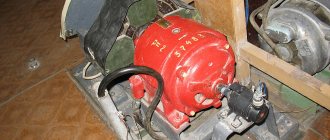
Scientists and inventors worked on the engine with the goal of using it for industrial needs. All of them sought to ensure that the engine core moved in a magnetic field in a rotational-translational manner, in the manner of a piston in the cylinder of a steam engine. Russian inventor B.S. Jacobi made everything much simpler. The principle of operation of its engine was the alternating attraction and repulsion of electromagnets. Some of the electromagnets were powered from a galvanic battery, and the direction of current flow in them did not change, while the other part was connected to the battery through a commutator, thanks to which the direction of current flow changed after each revolution. The polarity of the electromagnets changed, and each of the moving electromagnets was either attracted or repelled from the corresponding stationary electromagnet. The shaft began to move.
electric motor of Boris Jacobi Initially, the engine power was small and amounted to only 15 W, after modifications, Jacobi managed to increase the power to 550 W.. On September 13, 1838, a boat equipped with this engine sailed with 12 passengers along the Neva, against the current, while developing speed 3 km/h. The engine was powered by a large battery consisting of 320 galvanic cells. The power of modern electric motors exceeds 55 kW. For information on purchasing electric motors, see here.
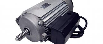
Operating principle and design of an asynchronous motor
An asynchronous (induction) motor is a mechanism that converts alternating current into mechanical power. By asynchronous we mean that the speed of movement of the stator magnetic force is higher than the same value of rotor revolutions.
In order to better understand what an asynchronous motor is and the operating principle of a three-phase asynchronous motor, where it is used and how it works, it is necessary to understand its components and details, and examine the technical characteristics. In addition, it will not be amiss to understand how force is converted during startup and where an asynchronous motor is used in practice.
In today's article we will try to answer the most interesting questions related to asynchronous motors, understand what the design of a single-phase asynchronous motor is, consider the principles of operation, as well as the pros and cons of this type of device.
A little history
The first such electric motor mechanism appeared back in 1888 and was introduced by the American engineer Nikola Tesla. However, his prototype device was not the most successful, since it was two-phase or multi-phase and the performance characteristics of the asynchronous motor did not satisfy consumers. Therefore, it was not widely used.
But thanks to the Russian scientist Mikhail Dolivo-Dobrovolsky, it was possible to breathe new life into the invention. It was he who took the lead in creating the world's first three-phase asynchronous motor.
This design improvement was revolutionary, since the operating principle of a three-phase asynchronous motor made it possible to use only three wires for operation, rather than four.
Advice
So there were no more obstacles left for the smooth launch of the device into mass production.
Today, due to their simplicity, these machines are widely used, and the mechanical characteristics of the asynchronous motor suit all drivers.
Every year, the share of asynchronous motors among all motors in the world is 90%.
Ease of use, the principle of operation of an asynchronous motor, easy starting, reliability and low cost, helped these motors spread throughout the world and literally make a technical revolution in industry.
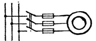
The operating principle of a three-phase motor is based on power from three phases of alternating current in a standard network. To operate, it requires exactly this kind of electricity and that is why it is called three-phase.
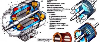
Three-phase motor device
Any asynchronous motor, regardless of its power and size, consists of the same parts; the mechanical characteristics of an asynchronous motor are also the same. The main components are:
- stator (fixed part of the machine)
- rotor (rotating part)
In addition, the following parts can be found in modern three-phase motors:
- shaft
- bearings
- winding
- grounding
- housing (in which all parts are mounted)
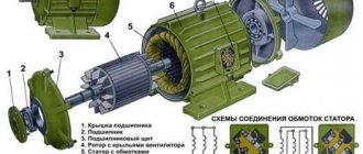
As mentioned above, the basic elements of the engine are the stator (fixed part) and the rotor (moving part).
The stator is made in the form of a cylinder; this element is composed of many metal, shaped sheets. The interior is designed to accommodate the winding. The centers of the windings are located at an angle of 120 degrees, and the connection is made based on the available voltage and two possible options: three or five contacts.
Operating principle.
The operation of an electric machine is based on the phenomenon of electromagnetic induction (EMI). The phenomenon of EMR lies in the fact that with any change in the magnetic flux penetrating a closed circuit, an induced current is formed in it (the circuit).
The motor itself consists of a rotor (the moving part - a magnet or coil) and a stator (the stationary part - the coil). Most often, the motor design consists of two coils. The stator is surrounded by a winding through which the current actually flows. The current generates a magnetic field that affects another coil. In it, due to EMR, a current is also formed, which generates a magnetic field acting on the first coil. And so everything repeats in a closed cycle. As a result, the interaction of the rotor and stator fields creates a torque that drives the motor rotor. Thus, electrical energy is transformed into mechanical energy, which can be used in various devices, mechanisms and even in cars.
Rotating magnetic field
Electric motor rotation
Classification of electric motors
All electric motors are classified among themselves primarily by the type of current flowing through them. In turn, each of these groups is also divided into several types, depending on technological features. DC motors
On low-power DC motors, the magnetic field is created by a permanent magnet installed in the device housing, and the armature winding is fixed to a rotating shaft. The schematic diagram of the DPT is as follows:
The winding located on the core is made of ferromagnetic materials and consists of two parts connected in series. Their ends are connected to the collector plates, to which the graphite brushes are pressed. One of them is supplied with a positive potential from a direct current source, and the other is supplied with a negative potential.
After power is applied to the motor, the following occurs:
- The current from the lower “positive” brush is supplied to the collector plate to the contact platform of which it is connected.
- The passage of current through the winding to the collector plate (indicated by a dotted red arrow) connected to the upper “negative” brush creates an electromagnetic field.
- According to the gimlet rule, a magnetic field of the south pole appears in the upper right part of the anchor, and a north magnetic field appears in the lower left part of the anchor.
- Magnetic fields with the same potential repel each other and cause the rotor to rotate, indicated in the diagram by a red arrow.
- The design of the collector plates leads to a change in the direction of current flow through the winding during inertial rotation, and the operating cycle is repeated again.
The simplest electric motor
Despite the obvious simplicity of the design, a significant drawback of such engines is their low efficiency due to large energy losses. Today, permanent magnet DCDCs are used in simple household appliances and children's toys.
The design of high-power DC motors used for industrial purposes does not involve the use of permanent magnets (they would take up too much space). These machines use the following design:
- the winding consists of a larger number of sections representing a metal rod;
- each winding is separately connected to the positive and negative poles;
- the number of contact pads on the collector device corresponds to the number of windings.
Thus, reducing energy losses is ensured by smoothly connecting each winding to the brushes and power source. The following picture shows the design of the armature of such an engine:
The design of DC electric motors makes it easy to reverse the direction of rotation of the rotor by simply reversing the polarity on the power source.
The functional features of electric motors are determined by the presence of some “tricks”, which include the shift of current-collecting brushes and several connection diagrams.
The shift of the current-collecting brush assembly relative to the rotation of the shaft occurs after the engine starts and the applied load changes. This allows you to compensate for “armature reaction” - an effect that reduces the efficiency of the machine by braking the shaft.
There are three ways to connect a DPT:
- The parallel-excitation circuit involves parallel connection of an independent winding, usually controlled by a rheostat. This ensures maximum stability of the rotation speed and its smooth adjustment. It is thanks to this that parallel-excited motors are widely used in lifting equipment, electric vehicles and machine tools.
- The series-excitation circuit also provides for the use of an additional winding, but it is connected in series with the main one. This allows, if necessary, to sharply increase the engine torque, for example, at the start of a train.
- A mixed circuit takes advantage of both connection methods described above.
Bipolar electric motor
AC motors
The main difference between these motors and the previously described models is the current flowing through their windings. It describes according to a sinusoidal law and constantly changes its direction. Accordingly, these engines are powered by alternating generators.
One of the main design differences is the design of the stator, which is a magnetic circuit with special grooves for the arrangement of winding turns.
AC motors are classified according to their operating principle into synchronous and asynchronous. In short, this means that in the first, the rotor rotation frequency coincides with the rotation frequency of the magnetic field in the stator, but in the second, it does not.
We strongly recommend reading our article on the design of AC electric motors.
Synchronous motors
The operation of synchronous AC motors is also based on the principle of interaction of fields arising inside the device, however, in their design, permanent magnets are fixed to the rotor, and a winding is passed through the stator. The principle of their operation is demonstrated by the following diagram:
The conductors of the winding through which the current passes, shown in the figure as a frame. The rotor rotates as follows:
- At a certain point in time, the rotor with a permanent magnet attached to it is in free rotation.
- On the winding, at the moment a positive half-wave passes through it, a magnetic field is formed with diametrically opposite poles Sst and Nst. It is shown on the left side of the diagram above.
- The like poles of the permanent magnet and the stator magnetic field repel each other and bring the motor to the position shown on the right side of the diagram.
In real conditions, to create constant smooth rotation of the motor, not one winding coil is used, but several. They alternately pass current through themselves, thereby creating a rotating magnetic field.
By design:
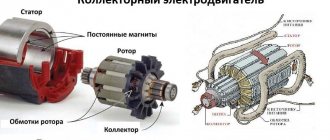
A commutator motor is an electric motor in which a brush-commutator assembly is used as a rotor position sensor and current switch.
A brushless electric motor is an electric motor consisting of a closed system that uses: control systems (coordinate converter), power semiconductor converter (inverter), rotor position sensor (RPS).
• Driven by permanent magnets; • With parallel connection of armature and field windings; • With a series connection of the armature and field windings; • With mixed connection of armature and field windings;
three-phase asynchronous motors
By synchronization:
• Synchronous motor
– AC electric motor with synchronous movement of the magnetic field of the supply voltage and the rotor.
• Asynchronous electric motor
– an alternating current electric motor with a different frequency of rotor movement and a magnetic field generated by the supply voltage.
See also:
- Volkswagen New Beetle
- Opel Ascona A
- Daewoo Lanos
- History of the road sign
- BMW E65-E66
- Airless tires
- BMW Z8