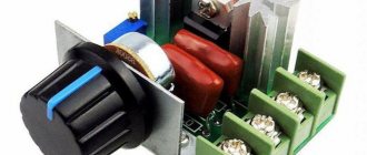
To control the voltage in the network, electronic rectifiers are used. These devices work by changing the frequency. Many modifications are allowed to be used on AC power.
The main parameters of rectifiers include conductivity. It is also worth considering the permissible overvoltage indicator. In order to understand the issue in more detail, we need to consider the rectifier circuit.
Device modifications
The rectifier circuit involves the use of a contact thyristor. The stabilizer is usually used as a transition type. In some cases, it is installed with a security system. There are also many modifications using triodes. These devices operate at a frequency of 30 Hz. They are good for collectors. The rectifier circuit also includes low conductivity comparators. Their sensitivity corresponds to at least 10 mV. A certain class of devices is equipped with a varicap. Due to this, modifications can be connected to a single-phase circuit.
Principle of operation
The radio engineering term thyristor is made up of two parts. The word used at the beginning is thyra, which means “door” or “entrance” in Greek. Then the ending of the English word resistor is used, which is translated as “resistance”.
A thyristor is a semiconductor device where more than two p-n junctions are assembled on the basis of a single crystal. The essence of the electron-hole connection of a pair of chemical elements - this is how the concept of “p - n junction” is deciphered - is that when direct current is connected, a potential difference appears at the terminals. With reverse current, charge carriers are blocked.
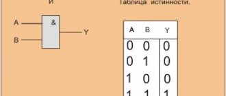
A signal contact is switched into the device , the purpose of which is to control the breakdown current of the boundary of differently charged zones. On electrical diagrams, the symbol for a thyristor almost coincides with the symbol for a diode. The difference is that the control electrode arrow is attached to the cathode terminal.
Device design
A semiconductor device is a structure formed by four layers of different polarities connected in series. A chain of p - n - p - n type is formed. The anode terminal is connected to the outer layer with a positive charge, and the cathode is connected to the negative semiconductor. Up to two control contacts can be connected to the internal layers.
The fundamental element of a thyristor is a silicon crystal with a given thickness. To form the p-layer, boron and aluminum impurities are used. To obtain the n-region, phosphorus is used. Additives are applied using diffusion technology. At temperatures from 1000° C to 1300° C, a transition layer with a depth of 60 microns is created.
The appearance of modern devices is different from parts made two decades ago. They used to look like “flying saucers.” The negative electrode and signal contact were located at the end, and the anode terminal was installed on the opposite side or side of the product. Now the thyristor is a small plastic box with three electrodes at the bottom. The location of the contacts is indicated in the device description.
You might be interested in this: Digital multimeter and multitester measurement
Operating modes
The operating principle of a thyristor is characterized by operation in two stable states. The “closed” position indicates low conductivity. The value "open" indicates high electrical conductivity.
How a thyristor works will be explained for dummies by a diagram of the dependence of current on voltage. In the initial position, the semiconductor element is locked.
Even a significant increase in the potential difference across the contacts will not bring the device into working condition. The graph line is almost horizontal.
But as soon as current is applied to the control terminal, the thyristor opens. At this moment, the linear segment on the graph abruptly changes its angle of inclination, close to the vertical position. The level of breakdown voltage depends on the magnitude of the signal current. The current-voltage characteristic explains why the use of a control electrode is required. Once the command signal is reset, the device will remain open until the voltage decreases to the hold level.
The operation of the transistor is also based on the interaction of p-n junctions. The thyristor element differs from a semiconductor triode, which, like a valve, smoothly regulates the voltage by an abrupt increase in the potential difference after the appearance of a control signal. A kind of electronic key, upon command, opens the way to power the electrical circuit.
Semiconductor models
Semiconductor rectifiers are great for step-down transformers. Many modifications are produced based on connector capacitors. Their input conductivity does not exceed 10 microns. It is also worth noting that semiconductor rectifiers differ in sensitivity. Devices up to 5 mV can be used at 12 V.
Their protection systems are of class P30. Adapters are used to connect modifications. At a voltage of 12 V, the reboot parameter is on average 10 A. Modifications with plates are distinguished by their high operating temperature. Many devices can be powered by transistors. Filters are used to reduce distortion.
Features of thyristor devices
The thyristor rectifier is designed to regulate voltage in a DC network. If we talk about low-conductivity modifications, they use only one triode. The maximum voltage when loading at 2 A is at least 10 V. The protection system for the presented rectifiers is usually used in class P44. It is also worth noting that the models are well suited for power conductors. How does a thyristor rectifier transformer work? First of all, the voltage goes to the relay.
DC conversion occurs thanks to a transistor. Capacitor blocks are used to control the output voltage. Many models have multiple filters. If we talk about the disadvantages of rectifiers, it is worth noting that they have high heat losses. When the output voltage is above 30 V, the overload indicator is significantly reduced. Additionally, it is worth considering the high price of a thyristor rectifier.
Mounting diagram
Another practical application of the SCR thyristor in DC circuits is as a "mount" device for overvoltage protection. The "mount" circuit consists of an SCR thyristor installed in parallel with the output of a constant voltage source to establish a short circuit across the output of that power supply to prevent too much voltage from being applied to the load. Damage to the SCR thyristor and power supply is prevented by installing a suitable fuse or significant series resistance in front of the SCR thyristor to limit the short circuit current (figure below).
"Mount" circuit used in a DC power supply
Some device or circuit that detects the output voltage will be connected to the control electrode of the SCR thyristor, so when an overvoltage condition occurs, a voltage will be applied between the control electrode and the cathode, turning on the SCR thyristor and causing the fuse to blow. The effect will be about the same as throwing a steel pry bar directly onto the output terminals of the power supply, hence the name of the circuit.
Most applications of SCR thyristors are for controlling AC power, even though SCR thyristors are direct current (unidirectional) devices. If a circuit requires bidirectional current flow, multiple SCR thyristors can be used, with one or more thyristors looking in each direction to handle both half-cycles of the AC wave. The main reason why SCR thyristors are used at all in AC power management applications is the thyristor's unique response to alternating current. As we have seen, a thyratron tube (a vacuum tube version of an SCR thyristor) and a symmetrical dynistor (DIAC), a hysteresis device driven during part of an AC half-cycle, will turn on and remain on for the remainder of the half-cycle as long as the AC will not decrease to zero, since the next half-cycle must begin. Just before the zero crossing point of the AC signal, the thyristor will turn off (turn off) due to insufficient current (this behavior is also called natural commutation) and must turn on again in the next period. The result is a circuit current equivalent to a “truncated” sine wave. As an example, below is a graph of the response of a symmetrical dynistor (DIAC) to an alternating voltage whose peak value exceeds the switching voltage of the DIAC.
Bidirectional response of symmetrical dynistor (DIAC)
When using DIAC, the switching voltage limit was a fixed value. With an SCR thyristor, we control exactly when the device is triggered by switching the control pin at any point in the signal period. By connecting a suitable control circuit to the control electrode of the SCR thyristor, we can “cut” the sine wave at any point to provide time-proportional control of power to the load.
Let's take the circuit in the figure below as an example. Here an SCR thyristor is placed in the circuit to control the load power drawn from the AC source.
AC Power Control Using SCR Thyristor
Being a unidirectional (one-way) device, the most we can supply to the load is only one half-wave during an AC half-cycle when the polarity of the supply voltage is positive at the top and negative at the bottom. However, for demonstrating the basic idea of time-proportional control, this simple circuit is better suited than a circuit that controls power throughout the entire wave (which would require two SCR thyristors).
If there is no switching at the control electrode and the AC source voltage is significantly below the rated switching voltage of the SCR thyristor, the SCR thyristor will never open. Connecting the SCR thyristor's control electrode to the anode via a standard rectifier diode (to prevent reverse current flow through the control terminal in case the SCR thyristor contains a built-in resistor between the control terminal and the cathode) will allow the SCR thyristor to fire almost immediately at the beginning of each positive half cycle (figure below).
The control electrode is connected directly to the anode via a diode; Almost a whole half-wave of current flows through the load.
Bridge modifications
Bridge rectifiers operate at a frequency of no more than 30 Hz. The control angle depends on the triodes. Comparators are mainly attached via diode conductors. The models are not best suited for power equipment. Stabilizers with a low-resistance adapter are used for the modules. If we talk about the disadvantages, then we should take into account the low conductivity at high voltage. Protection systems are usually used in class P33.
Many modifications are connected via a dipole triode. How does the transformer work on these rectifiers? Initially, voltage is applied to the primary winding. When the voltage exceeds 10 V, the converter is switched on. The frequency is changed using a conventional comparator. In order to reduce heat losses, a varicap is installed on the bridge controlled rectifier.
Power devices
Power rectifiers have recently become very popular. The overload indicator at low voltage does not exceed 15 A. The protection system is mainly used in the P37 series. The models are used for step-down transformers. If we talk about design features, it is important to note that the devices are produced with pentodes. They are distinguished by good sensitivity, but they have a low operating temperature.
Capacitor blocks can be used at 4 microns. Output voltage above 10 V activates the converter. Filters are usually used for two insulators. It is also worth noting that there are many rectifiers with controllers on the market. Their main difference lies in the ability to operate at frequencies above 33 Hz. In this case, the overload on average corresponds to 10 A.
Full-wave modifications
A full-wave single-phase rectifier is capable of operating at different frequencies. The main advantage of the modifications lies in the high operating temperature. If we talk about design features, it is important to note that power thyristors are used of the integral type, and their conductivity does not exceed 4 microns. At a voltage of 10 V, the system produces an average of 5 A.
Protection systems are quite often used in the P48 series. Modifications are connected via adapters. It is also worth noting the disadvantages of rectifiers of this class. First of all, this is low susceptibility to magnetic vibrations. The overload parameter can sometimes change quickly. At frequencies below 40 Hz, current drops are felt. Experts also note that the models are not able to work on one filter. Additionally, field-effect transistors are not suitable for the devices.
Specifications
The applications of semiconductors are varied. Depending on what the thyristor is needed for, a part with the required technical data is selected. will help you select the required type of semiconductor triode :
- Maximum current from anode to cathode.
- The maximum reverse current value is indicated only for types with this function.
- Maximum direct-flow voltage in the “open” position.
- Minimum voltage and opening current of the p-n junction.
- The limiting level of the signal current leading to breakdown of the thyristor.
- The holding current determines the level below which the “closed” state occurs.
- Power indicates the amount of permissible load.
- Response time.
Single-phase devices
A single-phase controlled rectifier is capable of performing many functions. Models are most often installed on power transformers. At a frequency of 20 Hz, the overload parameter on average does not exceed 50 A. The protection system for rectifiers is of class P48. Many experts say that the models are not afraid of wave interference and cope well with impulse surges. Are there any disadvantages to this type of model? First of all, they relate to low current at high load. To solve this problem, comparators are installed. However, it is worth considering that they cannot operate in an alternating current circuit.
Additionally, problems with current conduction periodically arise. On average, this parameter is 5 microns. Reducing sensitivity greatly affects the performance of the triode. If we consider single-phase uncontrolled rectifiers, then their plates are used with an adapter. Many models have multiple isolators. It is also worth noting that rectifiers of this type are not suitable for step-down transformers. Stabilizers are most often used for three outputs, and their maximum voltage should not exceed 50 V.
Controlled rectifiers
3. CONTROLLED RECTIFIERS.
3.1 Thyristors in controlled rectifiers.
In industrial and transport electric drives, in powerful electrothermal and electrotechnological installations, controlled rectifiers (RC) are used, in which, unlike uncontrolled rectifiers, it is possible to change and regulate the parameters of the output energy (voltage, current). Regulation of their output voltage can be carried out in various ways: using adjustable transformers, using resistive or capacitive dividers and using controlled valves - thyristors. The latter method is currently the most widely used.
Thyristors are controlled diode-type semiconductor devices (Fig. 3.1.1) having three pn junctions. The outermost P-region is called the anode, the other outermost N-region is called the cathode, and the output from one of the central regions is called the control electrode (CE). Depending on the location of the UE, thyristors are divided into devices with cathode control (Fig. 3.1.1, a) and devices with anode control (Fig. 3.1.1, c). The current-voltage characteristic of a thyristor (Fig. 3.1.2) differs from the current-voltage characteristic of a diode only in the region of forward voltages in that the thyristor is switched into a conducting state by applying current Iу to the control electrode. Turning on thyristors in the HC “at the anode” by applying voltage U>Uon is undesirable due to possible damage to the device. After switching on, the UE loses its control properties and, therefore, is unable to turn off the device. To turn off the thyristor, you must either reduce the current to the value I or change the polarity of the voltages at the anode (Fig. 3.1.3).
In HC, the polarity of this voltage changes periodically with the frequency of the supply network, which ensures the so-called natural blocking of thyristors. It should be noted that thyristors are susceptible to spontaneous activation when the voltage at the anode changes rapidly. This phenomenon, called the “dU/dt effect,” limits the permissible rate of rise of the forward voltage to 20 ... 100 V / μs. Other parameters of thyristors are:
— permissible direct Uon and reverse Urev. add. voltage (Fig. 3.1.2), components for different types of thyristors from 100 to 6000 V;
— permissible average forward current Ipr. additional (for powerful thyristors up to 2000A);
— amplitude Iу, duration tуу and rate of increase dIу/dt of the control current pulse;
— turn-on times ton and turn-off times toff.
For modern thyristors, ton is a few microseconds, and toff ranges from 20 to 500 microseconds.
Note that only after toff can direct voltage Upr be reapplied to the thyristor, otherwise the device turns on spontaneously. The equivalent circuit of a thyristor in the region of forward voltages does not differ from the diode circuit (see section 2.4), and the static power loss is determined by formula (2.5.8) taking into account (2.5.5) and (2.5.6). To calculate the power of switching losses, the following relation is valid:
, (3.1.1)
where UK, IK – switched voltages and currents; TK – switching period.
In addition to the main type of thyristors, domestic and foreign manufacturers produce a number of varieties.
A triac is a symmetrical thyristor (Fig. 3.1.4, a, b, c), designed for switching in alternating current circuits and replaces a circuit of two back-to-back thyristors connected in parallel with a common control electrode. Thus, the KU208G triac can switch alternating current up to 10A at voltages up to 400V.
Lockable (two-operation) thyristors (Fig. 3.1.4d) allow you to turn off the anode current by applying a negative pulse to the control electrode. The required power of the locking control pulse is significantly higher than the power of the unlocking pulse. The use of turn-off thyristors in power electronics is becoming increasingly widespread in the range of currents up to 200A and voltages up to 1000V.
Photothyristors and phototriacs (Fig. 3.1.5, a) are thyristors and triacs with photoelectronic control, in which the UE is replaced by an infrared LED and a photodetector with a control circuit. The main advantage of such devices is the galvanic isolation of the control circuit from the power circuit. They can also be used to control higher power thyristors or triacs. The low consumption of the control circuit allows such devices to be connected to the output of microprocessors and microcomputers (Fig. 3.1.5, b) for digital control of the current in the RN load, with a power of up to 60 W, connected to the AC network.
3.2 Block diagram and principle of operation
controlled rectifier.
The block diagram of the CF (Fig. 3.2.1,a) differs from the block diagram of the uncontrolled rectifier (Fig. 2.1.1) in that the block of uncontrolled valves VB is replaced by an adjustable valve block (VB) and a voltage-synchronized control system (CS) is introduced networks.
Regulation of the rectified voltage U0,a using thyristors is based on a shift in the moment of switching on the controlled valve compared to the start of operation of the uncontrolled valve (Fig. 3.2.1, c). The angle corresponding to this shift is called the inclusion angle a. Obviously, a can be adjusted within the positive half-wave of voltage u1, i.e. 0≤α≤p. Moreover, if the thyristor turns on at a=180°, then the voltage U0,a=0. This control method is called phase-pulse.
The ability of a shock wave to change the rectified voltage is assessed by its control characteristic, which is the dependence of the average value of the rectified voltage U0,α on the switching angle.
For generality of results, the control characteristic U0,α=f(α) is often presented in normalized form
, (3.2.1)
where is the voltage at the switching angle equal to zero (m2 ³ 2).
The type of control characteristic depends on a number of factors: the rectifier circuit, the type of filter and the nature of the load, etc. CFs are built according to the same principles as uncontrolled rectifiers (see Fig. 2.2.1). In push-pull HCs, all valves can be controlled (symmetrical circuit, Fig. 3.2.2, c, d). In order to simplify the control system and reduce the cost of the shock wave, it is possible to use asymmetrical circuits (Fig. 3.2.2d), in which one group of valves (anode or cathode) is replaced with diodes. In a shock wave with an inductive load, to improve the energy characteristics, a zero (branch) diode VD0 is introduced (Fig. 3.2.2, b, d).
3.3 Controlled rectifiers when operating on an active load.
The equivalent circuits of thyristor rectifiers are identical to the equivalent circuits of uncontrolled rectifiers (see the diagram in Fig. 3.3.1, a and Fig. 2.4.1, b). The only difference is that uncontrolled valves are replaced with controlled ones - thyristors. The methodology for analyzing rectifier circuits is also preserved (Section 2.5).
Multiphase SW operate in continuous current mode at small switching angles (Fig. 3.3.1, b), and at large angles (Fig. 3.3.1, d) - in intermittent current mode. The switching angle a, corresponding to the boundary of the modes (Fig. 3.3.1, c) of continuous and intermittent currents, is called the critical angle
(3.3.1)
For single-phase rectifiers (Fig. 3.3.2, a, b) acr = 0 and at a>0 they operate in intermittent current mode. Taking into account (2.5.2) and (3.2.1), the normalized equation and graph of the control characteristic of the shock wave under active load look like (Fig. 3.3.3)
(3.3.2)
It should be noted that with increasing switching angle a of the thyristor, there is a rapid increase in the ripple coefficient.
| b) |
| a) |
| Rice. 3.3.1. Equivalent circuit (a), and diagrams (b, c, d), of the rectified voltage U0,a for a three-phase single-cycle circuit with an active load at different values of the thyristor switching angle a. |
| Rice. 3.3.3. Regulatory characteristics of rectifiers when operating on an active load (a), the influence of the switching angle on the pulsation coefficient (b). |
3.4 Controlled single-ended rectifiers
with active-inductive load
.
When drawing up the equivalent circuit (Fig. 3.4.1, a), we used the premises stated earlier for uncontrolled rectifiers with an active-inductive load (section 2.6). Under the influence of EMF, current flows through the valve even when the phase EMF of the valve winding of the transformer e2 has changed direction. Therefore, at thyristor switching angles a>acr, the rectified voltage u'0,a at the filter input has negative voltage sections (Fig. 3.4.1c). In these areas, the load is a source of energy, i.e. it returns the energy previously accumulated in the inductance back to
| Rice. 2.4.1. Equivalent circuit (a), wave diagrams of voltage U0,a and current i0,a (b, c) regulation characteristic (d) and ripple coefficient Kp(1) (e) of a controlled three-phase single-act rectifier with an active-inductive load. Continuous current mode (pm2wl0 >>R0) |
power supply network. Part of this energy is lost in active resistance R0. With a sufficiently large inductance L0 (when pm2wL0>>R0) the load current i0,a
| Rice. 3.4.1. Equivalent circuit (a), wave diagrams of voltage u0,a and current i0,a (b, c), control characteristic (d) and ripple coefficient (e), of a controlled three-phase single-ended rectifier with an active-inductive load. Continuous current mode. |
is continuous and the current through the controlled valve always flows 1/m2 part of the period. In continuous current mode, taking into account (2.5.2) and (3.2.1), the equation and graphs of the control characteristic for m2³2 and p=1 look like (Fig. 3.4.1,d)
U*0,a = Сosa (3.4.1)
If the energy reserve in the magnetic field of inductance L0 is insufficient, then the voltage U0,a manages to drop to zero before the next thyristor is unlocked (Fig. 3.4.2a). Therefore, the control characteristic of the shock wave becomes flatter and is described by the equation:
(3.4.2)
where l is the valve current duration angle, depending on the ratio .
The switching effect due to the leakage inductance LS of the windings of the converter transformer, as in an uncontrolled rectifier (see Section 2.8), reduces (Fig. 3.4.2, b) in the interval of the commutation angle g the voltage U0,a to a value. At the same time, the average value of the rectified voltage also decreases.
(3.4.3)
The ripple coefficient at the filter input is determined by the formula
(3.4.4)
Due to the switching angle g, the ripple factor increases further.
In controlled rectifiers, when operating on both active and active-inductive loads, the switching angle a affects the ratio between active and reactive powers. As can be seen from Fig. 3.4.1, b and c, the current pulse of the operating valve is shifted in phase relative to the phase EMF by angle a (or by angle a+0.5g, taking into account the commutation effect). Therefore, the main harmonic of this current, and therefore the phase current i1,1 of the rectifier (Fig. 3.4.3, a), lags behind the mains voltage U1 by the same angle (a + 0.5g). As a result, the controlled rectifier loads the network with reactive power as a consumer with a phase shift coefficient.
(3.4.5)
where PC and QC are respectively the active and reactive power consumed by the rectifier from the network.
In the case of the rectifier operating on an inductive load, to improve the phase shift coefficient, a zero or branch diode VD0 is included in the circuit (Fig. 3.2.2, b, e and Fig. 3.4.4, a). When the EMF e2 becomes less than zero, the operating thyristor closes and the blocking diode VD0 opens. In this case, the current in the inductor L0 (coinciding with the load current i0,α) is not interrupted and flows along the L0-R0-VD0 circuit. When the next thyristor opens, the zero diode VD0 closes. The shaded sections of the current curve i0,α (Fig. 3.4.4, c) correspond to the current iV0 of the zero diode.
| A) |
| b) |
| V) |
Due to the zero diode in the u0,a curve (Fig. 3.4.4 b), the negative pads disappear and therefore the adjustment characteristic and the dependence of the ripple coefficient on the angle a become the same as with an active load (see section 3.8).
The neutral diode also improves the phase shift coefficient to a value of .
Control questions.
1. Design, current-voltage characteristics and principle of operation of a thyristor.
2. Types of thyristors and their characteristics.
3. Explain the oscillograms u'0,a and i0,a for different types of load and a=0; a=60 electrical degrees in a three-phase controlled rectifier (m3=3; p=1).
4. What factors determine the value of the power factor of a controlled rectifier.
5. Why is the power factor of a controlled rectifier lower than that of an uncontrolled one.
6. How does the branch diode affect the components of the total power of the SW and why.
3.5 Controlled push-pull rectifiers.
A three-phase push-pull (bridge) rectification circuit (uncontrolled or controlled) can be represented by a series connection of two single-cycle circuits powered from one group of valve windings of a transformer (see section 2.5, Fig. 3.5.1a). As in a single-cycle shock wave, continuous and intermittent current modes are possible (Fig. 3.5.1, b, c), and the critical switching angle is equal to
(3.5.1)
Equation of the control characteristic in normalized form for the circuit (Fig. 3.5.1, a)
at 0£a£acr. and for a>acr. (3.5.2)
The ripple frequency fп(1) is the basis of the harmonics of the rectified voltage, as in uncontrolled
| b) |
| Rice. 3.5.1. Equivalent circuit of a three-phase push-pull symmetrical shock wave (a) graphs (b) voltages and and graph of rectified voltage (c) for control angles , , , graph (d) dependences. |
| G)) |
| V) |
| G) |
| V) |
| Rice. 3.5.2. Equivalent circuit of a three-phase push-pull asymmetrical shock wave (a), graphs (b) of voltages and , graph of rectified voltage (c) for control angles ,, , graph (d) of dependence. |
rectifier, equal to m2pf1=6f1 (Fig. 3.5.1, c). The dependence (Fig. 3.5.1, d) of the pulsation coefficient Kp(1) on the control angle α indicates a rapid increase in Kp(1) with increasing a. For a single-phase push-pull SW circuit, the equation of the adjustment characteristic
, with αcr=0 (3.5.3)
With an inductive load response (pm2wL0>>R0), the equation of the control characteristic in normalized form for symmetrical push-pull rectifiers is described by equation (3.4.1).
An asymmetrical bridge rectifier (Fig. 3.5.2, a) is characterized by the fact that the ripple of the rectified voltage at a>0 has a fundamental harmonic frequency equal to 3f, as can be seen from the oscillograms (Fig. 3.5.2, c.) A decrease in the ripple frequency leads to the need to use more powerful filters. The dependences of the pulsation coefficient (Fig. 3.5.2,d) on the control angle for the main (3f) and second (6f) harmonics indicate a slower growth of Kp(2) in comparison with the growth of Kp(1). The equation of the control characteristic in normalized form for the circuits in Fig. 3.5.2,a and fig. 3.2.2g with an active or inductive load is described by expression (3.5.3). Compared to a symmetrical push-pull three-phase shock wave, an asymmetrical push-pull shock wave consumes a current from the supply network that contains both odd and even harmonics. This results in degraded distortion power.
The advantage of an asymmetrical push-pull shock wave is the lower value of reactive QS power consumed from the network.
Control questions:
1. Explain the oscillograms u'0,a and i0,a for different types of load and a=0, a=60 electrical degrees in a three-phase symmetrical and asymmetrical push-pull rectifier.
2. What are the advantages and disadvantages of asymmetrical circuits of controlled thyristor rectifiers.
3. Equations of the control characteristics of three-phase symmetrical and asymmetrical shock waves for different load types.
For medium and high power HCs, a mode is characteristic when the current i1 consumed by them (Fig. 3.4.3,b) is non-sinusoidal, and its first (fundamental) harmonic i1.1 is shifted relative to the phase voltage of the network u1 by an angle j
j=(a+0.5g) (3.6.1)
This leads to the presence in the hydrocarbons, in addition to the active (useful) power
PC=U1·I1,1·cosφ, (3.6.2)
also reactive power
QС=U1·I1,1·sinj, (3.6.3)
as well as the so-called distortion power
, (3.6.4)
which is created by the higher harmonic components of the current i1. Their specific gravity is characterized by the current distortion coefficient
(3.6.5)
where I1,1 is the effective value of the first (fundamental) harmonic of current i1, and I1 is the effective value of the current itself.
Total (volt-ampere) power of the hydrocarbons
(3.6.6)
Of the three components of this power, only active power is useful. Therefore, the PC/SC ratio characterizes the HC as a network load and is called the CM power factor. Using equations (3.6.2), (3.6.5), (3.6.6), we obtain the equation
KM=KI·cosj (3.6.7)
in the form of the product of the distortion coefficient of the current i1 by the phase shift coefficient of the latter relative to the voltage U1. Low CM values due to a highly distorted current shape i1, or due to a large value of the control angle a, require an increase in the installed power of the network, including transformer equipment, an increase in the cross-section of wires and an increase in insulation strength. Therefore, the IEC (International Electrotechnical Commission) standard IEC-555 limits the value of CM for electrical equipment that consumes more than 300 W of power from the network and has a rectifier (electrical appliances, computers, electronic equipment, power supplies, electric drives). The new IEC IEC standard that is coming into force tightens the requirements for power factor standards for power consumption of energy consumers and products entering the global market. In this regard, the task of improving the quality of power consumed by hydrocarbons from the network becomes important for developers of power supply devices for industrial equipment.
To reduce reactive power QS, circuits with a branching (zero) diode are used (see section 3.4); the main disadvantage of these circuits is the increase in TC due to increased distortion of the current waveform i2.
Other ways to reduce QC and TC is to install power capacitors at the input of the shock wave (Fig. 3.6.2, a), or
the use of filter compensating devices (Fig. 3.6.1) in the form of a system of multiphase oscillatory circuits tuned in voltage resonance to the frequencies of the most intense current harmonics i1 (5th, 7th, 11th, etc.) These
measures only partially improve KM, therefore, voltage regulation of the HC by the phase-pulse method is in practice carried out within relatively narrow limits and is combined with other methods, including voltage regulation by switching the stages of the converter transformer and using voltage booster circuits.
In step-controlled rectifiers (Fig. 3.6.2,b), contact (relays) or contactless (triacs) devices are used that connect controlled valves to a different number of turns of the valve windings of the converter transformer (with deep regulation, amax decreases and, therefore, QС and TS).
In circuits with voltage boost (Fig. 3.6.2, c), the minimum output voltage is provided by an uncontrolled rectifier using diodes VD1, VD2, and the increased voltage is achieved by turning on the thyristors.
Recently, the pulse-width method (PWM) of voltage regulation, based on the use of fully controllable (lockable) thyristors, has been used in hydrocarbons. With PWM control, thyristors are repeatedly turned on and off during a half-cycle of the supply voltage with a constant frequency f, significantly (and an integer times) higher than the frequency f1 of the mains voltage.
The output voltage u0,f in this case consists of high-frequency pulses (Fig. 3.6.2, d) of adjustable duration Ti, and the normalized control characteristic of the pulse is determined by their duty cycle
(3.6.8)
where is the return period, and g takes values from 0 to 1.
Control questions.
1. Why in controlled rectifiers the total power Sc exceeds the load power Pn.
2. What is the power factor of the hydrocarbons. What are the costs of operating at a low power factor?
3. Explain the operation of a single-phase rectifier with a zero diode. Why does the introduction of a neutral diode increase the power factor?
4. Explain the principle of operation of network filter compensating devices.
5. How will the distortion power Tc change if the inductance of the filter choke in the shock wave becomes equal to zero.
3.7 Rectifier control systems.
In addition to the power part (Fig. 3.7.1), the HC also includes a control system (CS), the main functions of which are: 1) determination of the thyristor unlocking moments depending on the control signal Ucontrol; 2) distribution of unlocking signals across phases to create current symmetry in the load ZH; 3) formation of control pulses of the required duration, amplitude and shape for reliable switching of thyristors along the control electrodes of the latter;
4) implementation of start-up, shutdown of hydrocarbons and protection from unauthorized operating modes. The shock wave can also have a feedback loop (FLC), the input of which receives the output parameter of the shock wave (voltage, current, power) for its stabilization or precise regulation using the control system.
Control systems in which the phase of control pulses can be adjusted are called PULSE PHASE. If the angle of supply of the control pulse is counted from a certain phase of the supply network voltage, then such control systems are called SYNCHRONOUS. With ASYNCHRONOUS phase-pulse control, the angle of supply of the control pulse is counted from the moment the previous control pulse is supplied.
The most common block diagram of the control system is the angle at which the thyristor is switched on (Fig. 3.7.2, a), using the vertical control method. The CC synchronization circuit, which generates signals Uc (Fig. 3.7.2, b), is connected to the supply network m1, f1, U1 and ensures synchronization of the control pulse repetition rate Uue with the frequency of the supply network (or the repetition frequency of the moments of natural switching of rectified voltage curves).
The FSU phase-shifting device, under the influence of the control voltage Ucontrol passing through the amplifier US, changes the thyristor switching angle a within the required limits (Fig. 3.7.2, b). With the vertical control method, the FSU contains a GR sweep generator (most often a sawtooth voltage generator) and a comparator K. The GR can be made according to a circuit with a diode switch, a transistor, an integrated operational amplifier with a capacitor in the feedback circuit, etc. The comparator can will be performed on a unijunction transistor, Schmidt trigger, operational amplifier, logic element, etc.
The control pulse shaper FUI is used to generate thyristor control signals with the required parameters. FUIs are divided into transistor, thyristor and optocoupler. Some schemes for controlling the thyristor switching angle are discussed in /5/.
The digital control system for the thyristor turn-on angle a generates a code for the phase of control pulses in digital form and converts it into the phase of control pulses. In the digital phase-shifting device in Fig. 3.7.3a, the four-bit control code Ku takes 16 values from 0000 to 1111 and is fed in parallel to the digital comparison circuit of the DSS.
The reference signal is also represented in the form of a K0p code and is generated by a subtractive counter ST, to the “-1” input of which a multivibrator MV is connected, producing rectangular pulses with a frequency fмв = 32f mains. The beginning of the formation of the reference code (Fig. 3.7.3, b) corresponds to the moment of natural switching of the HC valves. The moment of bitwise equality of Ku and K0n is fixed by the CSS and
| Rice. 3.7.2 Block diagram of the control system according to the vertical control method (a), timing diagrams (b) |
corresponds to control angle a. In this case, a logical signal 0 is generated at the output of the DSS. It is supplied to the output driver of the control system and, after amplification, is supplied to the control electrode of the thyristor. Transition to a digital form of control
improves accuracy, noise immunity and
| cop |
performance of control systems.
The most effective way to improve the control system is to use microprocessors in it (software-controlled devices for processing digital information and controlling the process of this processing, made using large-scale integrated circuit technology and placed on a miniature silicon crystal with an area of about 30 mm2). Due to its small size, the microprocessor is easily integrated into the control system (Fig. 3.7.4), the capabilities of which are significantly expanded as a result. ADC1 and ADC2 convert analog (time-continuous) master signals Uset and feedback Uoc into digital codes Ni(Uset) and Ni(Uoc), respectively.
The latter are sent from the ADC outputs to the MPC at discrete times 0, T, 2T, 3T,..., specified by the timer. Using digital codes representing the current values of Uoc and Uset, the MKT calculates (in accordance with the control algorithm and the program that implements it) the control action signals and issues them in digital form Ni(Ucontrol) through the output port in the VFI, activating its operation at the right times to control the midrange in order to obtain the output voltage Uo, a with the necessary parameters. The main advantages of microprocessor control are flexibility and versatility, the ability to rebuild the control algorithm by changing the processing program, expanding the functions of the control system, manufacturability, high reliability, repair
suitability. The signal power from the output of the FSU (analog, digital or microprocessor) is usually low.
VFIs provide amplification and formation of control pulses in shape, amplitude and duration before they are supplied to the thyristor UE (Fig. 3.7.5, a). The control diagram of the latter (Fig. 3.7.5,e) has a guaranteed unlocking area located between the boundary curves “A” and “B”. The diagram shows the lines of the maximum permissible values of voltage Uue, additional and current Iue, additional, as well as a curve of the permissible average power losses at the control electrode. With pulse control, the permissible pulse power is determined by the formula: (3.7.1)
If the duration of the control pulses is t and <50 μs, then the maximum value of the UE current must be increased (Fig. 3.7.5, c). The optimal shape of the control pulse (Fig. 3.7.5, a) is steep (slope of current rise
0.2…2.0 A/µs), a short (£0.1ms) peak with a maximum value (the maximum value of the pulse generated by the VFI) and is intended to clearly turn on the thyristor VS. The pedestal following the peak (its width is determined by the values of the commutation angle g and the thyristor holding current) ensures guaranteed opening of the thyristor in high- and medium-power shock waves. To improve the resistance of the thyristor to self-unlocking, a negative bias of (0.5...2.5) V is applied to the UE. The phase asymmetry of control pulses should not exceed (1.5...2.5) el. degrees.
The required duration of control pulses largely depends on the rectification circuit and the nature of the load. So, in a three-phase push-pull SW in the intermittent current mode, wide control pulses with a duration of more than 60 electrical degrees, or double narrow pulses with a shift of 60 electrical degrees are required. In shock waves intended to operate on the armature of a DC motor, double narrow pulses with a duration of 7...10 electrical degrees (400...550 μs) are used, and in shock waves intended to operate on the field windings of electrical machines (direct current or synchronous) - wide pulses with a duration 70...120 electrical degrees (3.9...6.6ms).
Get text
Parameters of two-phase devices
Two-phase rectifiers are produced for DC and AC circuits. Many modifications are operated on contact-type triodes. If we talk about the modification parameters, it is worth noting the low voltage at high overloads. Therefore, the devices are not well suited for power transformers. However, the advantage of the devices is considered to be good conductivity.
The sensitivity of the models starts from 55 mV. At the same time, heat losses are insignificant. Comparators are used on two plates. Quite often, modifications are connected through one adapter. In this case, the insulators are preliminarily checked for output resistance.
Performance monitoring
Before installing the thyristor in the circuit, you must ensure that it is in good working order. The integrity of the part is checked with a multimeter or a light bulb connected to a power source.
A dialing function is installed on the measuring device. First, the probes are connected to the anode and cathode alternately in the forward and reverse directions. The number “1” on the display will indicate that no current is flowing and the part is in good condition. Then the line from the anode to the signal contact is called.
One of the circuits should be open and the other will show little resistance. If in both cases the multimeter detects the same result, then the thyristor is faulty.
The functionality of the part can be checked by assembling a simple electrical circuit. The anode contact is connected to the positive terminal of the battery. The cathode is connected to the negative of the power source through the light bulb. A piece of wire briefly connects the anode and control terminals. The lamp should light up and not go out after breaking the anode-control electrode chain.
You might be interested in this: Connection diagram for a single-phase electricity meter Mercury 201
A working lighting device indicates the serviceability of the thyristor. When checking, it is necessary to take into account the amount of voltage supplied, which must be sufficient to turn on the lamp.
Three-phase modifications
Three-phase rectifiers are actively used on power transformers. They have a very high overload parameter and are able to operate under high frequency conditions. If we talk about design features, it is important to note that the models are assembled with capacitor units. Due to this, the modification can be connected to a DC circuit and not be afraid of wave interference. Pulse surges are blocked by filters. Connection via an adapter is carried out using a converter. Many models have three insulators. The output voltage at 3 A should not exceed 5 V.
Additionally, it is worth noting that rectifiers of this type are used under heavy network overloads. Many modifications are equipped with blockers. Frequency reduction occurs using comparators that are installed above the capacitor box. If we consider relay transformers, then an additional adapter will be required to connect modifications.
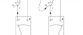
Checking the functionality of the SCR thyristor using a multimeter
A basic test of the performance of an SCR thyristor, or at least identification of the leads, can be performed with a resistance meter. Since the internal connection between the control electrode and the cathode is a PN junction, the multimeter should indicate continuity between these terminals with the red test lead on the control electrode and the black test lead on the cathode as follows (picture below).
Basic check of SCR thyristor
All other continuity measurements made on the SCR will show an "open" ("OL" on some digital multimeter displays). It should be understood that this test is very rough and is not a complete assessment of the SCR thyristor. An SCR thyristor can give good ohmmeter readings and still be faulty. Ultimately, the only way to test an SCR thyristor is to subject it to a load current.
If you use a multimeter with the "diode test" function, the gate-cathode junction voltage reading you get may or may not match what is expected from the silicon PN junction (approximately 0.7 volts). In some cases you will get readings of a much lower junction voltage: hundredths of a volt. This is due to an internal resistor connected between the control electrode and the cathode and included in some SCR thyristors. This resistor is added to make the SCR less susceptible to false triggering due to spurious voltage pulses, due to circuit "noise", or due to static electrical discharge. In other words, having a resistor connected across the control electrode and gate junction requires a larger switching signal (significant current) to turn on the SCR thyristor. This feature is often found in high power SCR thyristors rather than small ones. Don't forget that an SCR with an internal resistor connected between the gate and cathode will show continuity in both directions between those two terminals (picture below).
Large SCR thyristors have a built-in resistor between the control electrode and the cathode
Models with contact comparator
Controlled rectifiers with a contact comparator have recently been in great demand. Among the features of the modifications, it is worth noting the high degree of overload. Protection systems are mainly used in class P55. Devices with one capacitor box work. At a voltage of 12 V, the output current is at least 3 A. Many models can boast of high conductivity at a frequency of 5 Hz.
Stabilizers are quite often used of the low-resistance type. They perform well in AC circuits. In production, rectifiers are used to operate power transformers. Their permissible conductivity level is no more than 50 microns. The operating temperature in this case depends on the type of dinistor. As a rule, they are installed with several covers.
SCR thyristor startup delay
However, we can delay the firing of the SCR thyristor by inserting some resistance into the gate circuit, thereby increasing the amount of voltage drop required before sufficient SCR gate current is reached. In other words, if we impede the flow of electrons through the control electrode by adding resistance, the AC voltage will have to reach a higher point in its cycle before sufficient control terminal current is reached to turn on the SCR thyristor. The result is shown in the figure below.
A resistance is inserted into the control electrode circuit; Less than half a wave of current flows through the load.
When the half sine waveform is largely clipped by the SCR trigger delay, the load will receive less average power (power is supplied for less time over the entire period). By making the series resistor in the control electrode circuit variable, we can adjust the power in proportion to time (figure below).
Increasing the resistance increases the threshold level, resulting in less power reaching the load. Reducing the resistance lowers the threshold level, resulting in more power reaching the load.
Unfortunately, this control scheme has significant limitations. By using the AC source signal as the switching signal for our SCR thyristor, we are limiting control to the first half of the signal's half cycle. In other words, we cannot wait to switch the SCR thyristor after the signal peaks. This means that we can only reduce the power until the SCR thyristor turns on at the very peak of the signal.
Diagram for setting minimum power
Increasing the switching threshold will result in the circuit not starting at all, since even the peak AC voltage of the power supply will be insufficient to trigger the SCR thyristor. As a result, no power will be supplied to the load.
An ingenious solution to this control dilemma is found by adding a phase-shifting capacitor to the circuit (figure below).
Adding a phase-shifting capacitor to the circuit
The smaller signal shown on the graph represents the voltage across the capacitor. To illustrate the phase shift, I assume a maximum control resistance condition where the SCR does not start at all and does not supply any current to the load except for what little current passes through the control resistor and capacitor. This capacitor voltage will be 0° to 90° out of phase, lagging behind the AC signal. When this phase-shifted voltage reaches a high enough level, the SCR thyristor turns on.
When the voltage across the capacitor is sufficient to periodically trigger the SCR thyristor, the resulting load current signal will look something like the figure below.
The phase-shifted signal switches the SCR thyristor into conduction mode
Since the signal across the capacitor is still rising after the main signal from the power supply has reached its peak, it becomes possible to trigger the SCR at a threshold level beyond that peak value, thereby cutting the load current signal further than would be possible with a simpler circuit. In reality, the capacitor voltage signal is a little more complex than shown here, with its sine wave being distorted every time the SCR thyristor is turned on. However, what I am trying to illustrate here is the delayed actuation associated with a phase-shifting RC circuit; thus, a simplified, undistorted waveform serves this purpose well.
Devices with two comparators
Electronic rectifiers with two comparators are valued for their high output voltage. With an overload of 5 A, modifications are able to operate without thermal loss. The smoothing coefficient of rectifiers does not exceed 60%. Many modifications have a high-quality protection system of the P58 series. First of all, it is designed to cope with wave interference. At a frequency of 40 Hz, devices produce an average of 50 microns. Tetrodes for modifications are of variable type, and their sensitivity is no more than 10 mV.
Are there any disadvantages to this type of rectifier? First of all, it should be noted that they are prohibited from being connected to step-down transformers. In a DC network, the models have a low conductivity parameter. The operating frequency is on average 55 Hz. Modifications are not suitable for single-pole stabilizers. To use the devices on power transformers, two adapters are used.
SCR thyristors with sensitive control electrode
"Conventional" SCR thyristors, lacking an internal resistor, are sometimes called sensitive gate SCR thyristors due to their ability to be triggered by the slightest positive signal at the gate electrode.
The SCR Thyristor test circuit is useful as a diagnostic tool for testing suspicious SCR Thyristors, and is also an excellent aid for understanding the basic operation of SCR Thyristors. A DC power supply is used to power the circuit, and two push-button switches are used to enable and disable the SCR thyristor (picture below).
Circuit for checking SCR thyristors
Pressing the normally open "on" button connects the control electrode to the anode, allowing current to flow from the negative terminal of the battery through the cathode-control electrode PN junction, through the button, through the load resistor, and back to the battery. This gate current should cause the SCR to turn on, allowing current to flow directly from the cathode to the anode without further firing through the gate. When the "on" button is released, the load should remain energized.
Pressing the normally closed "off" button breaks the circuit, causing the current through the SCR to stop, thereby forcing it to latching (the amount of current is below the holding current).
The difference between modifications with an electrode triode
Controlled rectifiers with electrode triodes are valued for their high output voltage. At low frequencies they operate without thermal loss. However, it is worth considering that the overload parameter is on average 4 A. All this suggests that the rectifiers are not capable of operating in a DC network. Filters are only allowed to be used on two covers. The output voltage is usually 50 V, and the protection system is class P58. In order to connect the device, an adapter is used. The smoothing coefficient for rectifiers of this type is at least 60%.
Triggering SCR thyristors with complex circuits
SCR thyristors can also be triggered, or "unlocked", by more complex circuits. Although the previously shown circuit is sufficient for a simple application such as driving a lamp, control of large industrial motors often relies on more complex triggering circuits. Sometimes pulse transformers are used to connect the trigger circuit to the control electrode and cathode of the SCR thyristor to provide electrical isolation between the trigger circuits and the power circuits (picture below).
Transformer coupling of the switching signal provides isolation
When multiple SCRs are used to control power, their cathodes are often not electrically common, making it difficult to connect a single trigger circuit to all SCRs equally. An example of this is the controlled bridge rectifier shown in the figure below.
Controlled bridge rectifier
In any bridge rectifier circuit, the rectifier diodes (in this example rectifier SCR thyristors) must conduct current in opposite pairs. SCR1 and SCR3 must be started simultaneously, and SCR2 and SCR4 must be started as a pair. However, as you will notice, these pairs of SCR thyristors do not use the same cathode connections, meaning that the circuit will not work if you simply parallel their control electrodes and connect them to a single voltage source to drive both thyristors (picture below). ).
This strategy will not work for running SCR2 and SCR4 as a pair
Although the trigger voltage source shown will trigger SCR4, it will not properly trigger SCR2 because the two thyristors do not have a common cathode connection to use as a reference point for the trigger voltage. However, pulse transformers connecting the two thyristor control electrodes to the trigger voltage source will work (picture below).
Transformer coupling of control electrodes allows SCR2 and SCR4 to be triggered
Please note that this diagram shows the control electrode connections for only two of the four SCR thyristors. The pulse transformers and trigger sources for SCR1 and SCR3, as well as details of the pulse sources themselves, have been omitted for simplicity.
Controlled bridge rectifiers are not limited to single-phase circuits. In most industrial systems, AC power is available in three-phase form for maximum efficiency, and due to its advantages, they use solid-state control circuits. A three-phase controlled rectifier circuit based on SCR thyristors, not showing pulse transformers and trigger circuits, will look like the figure below.
Three-phase bridge load control using SCR thyristors
Models with capacitive triode
Controlled rectifiers with a capacitive triode are capable of operating in a DC network. If we consider the parameters of the modifications, we can note the high input voltage. In this case, the overload during operation will not exceed 5 A. The protection system is of class A45. Some modifications are suitable for power transformers.
In this case, much depends on the capacitor unit, which is installed in the rectifier. According to experts, the rated voltage of many modifications is 55 V. The output current in the system is 4 A. Filters for modifications are suitable for alternating current. The smoothing coefficient for rectifiers is 70%.
Holding current
If the SCR thyristor does not fire, the problem may be with the load rather than the thyristor. To keep the SCR thyristor on, a certain amount of load current is required. This minimum current level is called holding current. A load with too much resistance may not draw enough current to keep the SCR turned on when current through the gate electrode stops, giving the false impression of a bad SCR in the test circuit. Holding current values for different SCR thyristors are available from manufacturers. Typical holding current values range from 1 milliamp to 50 milliamps or more for large thyristors.
For testing to be comprehensive, more than switching behavior must be tested. The forward switching voltage of the SCR thyristor can be tested by increasing the DC source voltage (without pressing the buttons) until the SCR thyristor turns on on its own. Beware that the switching test may require very high voltages: many high-power SCR thyristors have switching voltage ratings of 600 volts or more! In addition, if a pulse voltage generator is available, the critical rate of increase in the SCR voltage of the thyristor can be checked in a similar way: it is necessary to subject the thyristor to pulse voltage at different voltage/time rates without affecting the push-button switches and observe when the thyristor turns on.
In this simple form, a circuit for testing SCR thyristors may be sufficient as a start/stop control circuit for a DC motor, lamp, or other practical load (figure below).
DC Motor Start/Stop Control Circuit
Devices based on channel triode
Controlled rectifiers with channel triodes have a high degree of conductivity. Models of this type are excellent for step-down transformers. If we talk about the design, it is worth noting that models are always produced with two connectors, and their filters are used on insulators. According to experts, conductivity does not change much at a frequency of 40 Hz.
Are there any disadvantages to these rectifiers? Heat losses are the weak point of the modifications. Many experts note the low conductivity of connectors that are installed on rectifiers. To solve the problem, kenotrons are used. However, they are not allowed to be used on DC power.
Difference between modifications
12V rectifiers are used for step-down transformers only. Comparators in devices are installed with filters. The maximum overload of modifications is no more than 5 A. Protection systems are quite often used in class P48. They are great for overcoming wave interference. Converter stabilizers with a high smoothing coefficient are also often used. If we talk about the disadvantages of modifications, it is worth noting that the output current in the devices is no more than 15 A.