Motor protection circuit breakers, or otherwise motor-automatic devices, are designed primarily to protect electric motors from overheating and the consequences of short circuits, and can also be used as a main or emergency switch. That is, in essence, they combine two devices in one housing - a circuit breaker and a thermal relay.
Previously, before automatic motors became widely used, thermal relays paired with a contactor were used to protect motors.
According to this scheme, the thermal relay, when the motor exceeds the load current consumed, opens the circuit of the contactor coil, disconnecting its power contacts and thus protecting the motor. The scheme is working, tested, but not without its shortcomings. First of all, they include the inability of thermal relays to protect against short circuits, so it is necessary to additionally use circuit breakers. And the dimensions of such a design consisting of a contactor and a thermal relay are quite large.
Therefore, with the advent of motor protection circuit breakers, thermal relays began to fade into the background and at the moment, their use is quite limited.
It’s worth saying right away that, in terms of their characteristics, motor circuit breakers are somewhat different from conventional circuit breakers. First of all, because:
- Time-current characteristics are taken into account. When starting the engine, the starting current can significantly exceed the rated current of the engine. More precisely, the starting current can be calculated knowing the rated current of the motor and the magnitude of the starting current multiple Kp (the starting current multiple to the rated value is Istart/Inom). This characteristic is indicated in the technical specifications; it is not on the engine nameplate. I start = In x Kp. For example, with a rated motor current of 20 A and a starting current multiple of 6, the starting current will be 120 A. At this current, a conventional circuit breaker with a time-current characteristic B (electromagnetic protection shutdown current from 3 In to 5 In, where In is rated current) or C (from 5·In to 10·In) can be switched off due to electromagnetic protection. Motor protection circuit breakers have a setting for the operation of the electromagnetic release, depending on the rating, ranging from 7.5 to 17.5 In.
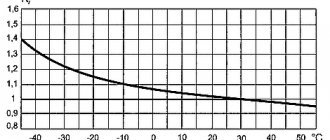
- All automatic motors have temperature compensation (from approximately -25 to +60 °C) in order to eliminate the influence of external temperature on the operation of the machine, since when the ambient temperature changes, the setting of the thermal release may change, which can in turn lead to false triggers.
- The maximum breaking capacity (maximum short-circuit current at which the device is able to disconnect the load) of motor protection circuit breakers is much higher (25-100 kA) than that of standard circuit breakers - 4.5 - 6 kA.
- Adjustable setting of the thermal release, depending on the motor rating.
Calculation of an automatic machine for an electric motor
Until recently, the following scheme was used to protect electric motors: a thermal regulator was installed inside the starter, connected in series with the contactor. This mechanism worked like this. When a large current passed through the relay for a long time, the bimetallic plate installed in it was heated, which, bending, interrupted the contactor circuit. If the excess of the set load was short-term (as happens when starting the engine), the plate did not have time to heat up and trigger the machine.
Internal structure of the motor protection circuit breaker in the video:
The main disadvantage of this scheme was that it did not save the unit from voltage surges, as well as phase imbalance. Nowadays, the protection of electric power plants is provided by more accurate and modern devices, which we will talk about a little later. Now let’s move on to the question of how to calculate the machine that needs to be installed in the electric motor circuit.
To select a protective circuit breaker for an electrical installation, you need to know its time-current characteristics, as well as its category. The time-current characteristic does not depend on the rated current for which the AV is designed.
To prevent the circuit breaker from tripping every time the motor is started, the value of the starting current should not be greater than that which causes the device to immediately operate (cut-off). The ratio of the starting current and the nominal value is specified in the equipment passport, the maximum allowable is 7/1.
When calculating the machine practically, you should use the reliability coefficient, denoted by the symbol Kn. If the rated current of the device does not exceed 100A, then the value of Kn is 1.4; for larger values it is 1.25. Based on this, the value of the cut-off current is determined by the formula Iots ≥ Kn x Istart. We select the circuit breaker in accordance with the calculated parameters.
Another value that must be taken into account when selecting when the machine is mounted in an electrical panel or a special cabinet is the temperature coefficient (CT). This value is 0.85, and the rated current of the protective device should be multiplied by it when selecting (In/Kt).
Selecting a circuit breaker
In the case of direct starting, when the engine is put into operation using an automatic motor and a contactor, you must first know its power. This information can be found either in the technical specifications for the engine, or in the passport data that is indicated on the nameplate.
The next step is to select an automatic machine based on the rated engine power. From various manufacturers you can find performance tables that indicate the rated operating current and the adjustment range of the circuit breakers depending on the engine power. In particular, the figure below shows the correspondence table for Allen Bradley motor protection circuit breakers.
And the last step is to set the required shutdown current using the range regulator. It is usually specified that it must be greater than or equal to the rated current of the motor. But it is desirable that the protection operation current exceeds the rated motor current by 10-20%.
That is, if the rated current of the motor is, for example, 10 A, we multiply this value by 1.1. We get 11 A. This current value is set by the regulator.
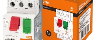
And I also wanted to say a few words about the design of the automatic motor. First of all, it should be noted that according to the control method, there are two types of machines - push-button and with a rotary switch. Also, the terminals can be either screw or with spring contact (used for motors with power up to 2 kW). You can also note the presence of a Test button on the front side of the case, which allows you to simulate the operation of the machine’s protection to check its functionality.
And in conclusion, I would like to note that operating motors without protective devices often leads to their failure due to overload, phase loss, voltage surges, etc. And this, in turn, leads to financial costs and equipment downtime. Therefore, motor protection circuit breakers are a necessary element and you should not skimp on them, especially since their prices are currently quite reasonable.
Connection diagrams
After the intermediate relay has been installed in the electrical cabinet, it should be connected to the electrical circuit. For this purpose, the contacts of the coil itself and direct contact elements are used. The relay usually has several pairs of NO normally open and NC normally closed contacts. The normal position is considered to be the absence of a signal to the coil. Since the coil does not have polarity, the contacts are connected arbitrarily.
Such a device is installed in control and automation circuits. Located between the actuator (for example, a contactor) and the reference source. The figure shows the electrical diagram of the device:
The picture shows an intermediate relay without voltage supply. If you apply it, the contacts will switch. The voltage in the coil can be different: 220, 24 and 12 volts.
How to connect the device is shown in the figure below:
In some cases, an intermediate type relay is used as a contactor, then the installation diagram will look like this:
As you can see, the intermediate relay has three groups of contacts that control the load and one group to hold the current in the coil. You can install an additional contactor, then the device is connected first to the contactor.
This device can also be connected to a motion sensor. Thanks to it, it is possible to connect several powerful lamps to the motion sensor system. Installation occurs as follows: the winding of the device is connected to the sensor, and the power contact switches the load in the lighting system. How to install such a sensor is shown below:
Another option for installing an electronic starter is to a thermostat. The diagram is shown in the picture (click to enlarge):
In this case, the thermostat and starter are connected in sequential order to the first phase and neutral wire (in the diagram they are designated as T1 and K1, respectively). The installation of the remaining contacts of the starter is carried out evenly between other phases.
Finally, we recommend watching a useful video on the topic:
https://youtube.com/watch?v=d6BA3PFlwCU
That's all I wanted to tell you about how to properly connect this device. We hope that the video instructions and intermediate relay connection diagrams provided were useful to you!
Electric motor 15 kW current
There are many varieties of 15 kW motors, but they all have different characteristics. Let's look at examples of such engines.
The most common examples of engines are:
- Asynchronous electric motor 4AM160S4 15/1460 380-660V;
- Electric motor 15 kW 1500 rpm;
- Electric motor 15 kW at 3000 rpm AIR160S2 and 15 kW at 1500 rpm AIR160S4;
- Electric motor AIR160S2 15.0 kW 3000 rpm AIR 160 S2;
- Electric motor 15 kW 1000 rpm AIR160M6.
All are united by two characteristics, this is a power of 15 kW and three-phase, and the type of motor - asynchronous and, of course, the presence of a contactor. Other characteristics, such as rotation speed, rotor type and brand, are all different. Electric motors of this type are designed to perform work from a network with alternating current frequency of 50 Hz and are manufactured for the following rated voltages:
- 220 V;
- 380V/220V;
- 380 V;
- 660 V;
- 380V/660V.
For more selection options and information about machines for electric motors, see the video on the next tab.
Motor protection by automatic switch. Practical calculations
A special feature of protecting the electric motor from overloads and short circuits is the increased starting current, which can be seven times the rated value. The strongest overloads at the start are characteristic of asynchronous motors with a squirrel-cage rotor, which are most used in everyday life and in production, therefore their proper protection, as well as the protection of the electrical wiring of the power supply circuits of electric motors, are especially relevant.
In household electrical engineering, the problem with large starting currents of electric motors is solved with the help of automatic switches, in which the shutdown (cutoff) does not occur immediately after exceeding the rated current, but after some time.
This period of time, which depends on the time-current characteristics of the circuit breaker, should be enough for the motor shaft to spin up to operating speed and the current consumption to drop to the nominal level. But circuit breakers do not have the flexibility of precise adjustment, so special protective devices are used to protect electric motors.
Conventional three-phase circuit breaker is often used to protect electric motors
Tasks of devices for protecting electric motors
Household electrical equipment is usually protected from large inrush currents in networks using three-phase circuit breakers that operate some time after the current exceeds the rated value. Thus, the motor shaft has time to spin up to the desired rotation speed, after which the force of the electron flow decreases. But the protective devices used in everyday life do not have precise settings. Therefore, the choice of a circuit breaker that allows you to protect an asynchronous motor from overloads and short-circuit overcurrents is more complicated.
Modern motor protection circuit breakers are often installed in a common housing with starters (the so-called motor starting switching devices). They are designed to perform the following tasks:
- Protecting the device from overcurrent occurring inside the motor or in the power supply circuit.
- Protection of the power unit from phase conductor breakage, as well as phase imbalance.
- Providing a time delay that is necessary so that the motor, which is forced to stop as a result of overheating, has time to cool down.
Control and protective automation for the engine on video:
- Shutting down the installation if the load is no longer supplied to the shaft.
- Protection of the power unit from long overloads.
- Protection of the electric motor from overheating (to perform this function, additional temperature sensors are mounted inside the unit or on its body).
- Indication of operating modes, as well as notification of emergency conditions.
It is also necessary to take into account that the circuit breaker for protecting the electric motor must be compatible with control and control mechanisms.
Functions of motor protective devices
Modern protective devices, or in other words, electric motor protection circuit breakers (automatic motor circuit breakers), are often combined in the same housing with starting switching devices (starters) and perform the following functions:
- Protection against short circuit current in the power supply circuit or inside the electric motor;
- Protection against long-term overloads associated with excessive mechanical load on the motor shaft;
- Protection against phase asymmetry (imbalance), or phase wire breakage;
- Thermal protection against engine overheating, carried out using additional temperature sensors installed on the casing or inside the electric motor;
- Protection against low-quality voltage;
- Providing a time delay for cooling the engine after its emergency stop after overheating;
- Indication of operating modes and emergency conditions;
- Optional – shutdown when the load on the shaft disappears (for example, for water pumps);
- Compatible with automatic monitoring and control systems.
Automatic motor with manual adjustment and automatic control
Previously, and until recently, the most used motor protection scheme was the connection of a thermal relay in the starter housing, in series with the contactor. During a prolonged overload, the bimetallic plate of the thermal relay heats up and interrupts the self-retaining circuit of the contactor. A short-term excess of the rated load when starting the motor is insufficient to heat and activate the bimetallic plate. You can read more about the thermal relay and its connection in the corresponding section of this resource.
Electric motor contactor with thermal relay
Selection of circuit breaker
Since the first two functions can be performed by conventional circuit breakers, many users use them to protect their electric motors. The main disadvantage of this method is the lack of protection against imbalance, phase failure and voltage surges. The selection of a circuit breaker is carried out according to its time, current characteristics and the maximum starting current of the electric motor.
Three phase circuit breaker
To choose the right circuit breaker by category and rated current, you need to study its time and current characteristics, which are described in detail on one of the pages of this site. The categories of circuit breakers (A, B, C, D) are determined by the ratio of the cut-off current of the electromagnetic release to the rated value. It must be borne in mind that the time-current characteristic of the category does not depend on the rating of the circuit breaker.
Time-current characteristics of circuit breakers of category “C”
To prevent false operation of the circuit breaker when starting the electric motor, it is necessary that the short-term starting current (Istart) does not exceed the cut-off value (instantaneous operation, Iinst.sr) of the machine. The ratio of the starting (Istart) and rated current (In) can be found out from the tag or passport of the electric motor, the maximum value of Istart/In=7.
Engine power tag
Practical calculations
In practice, a reliability correction factor Kn is used, which for machines with In<100A is equal to 1.4, and for In>100A they take Kn=1.25. Therefore, the condition Imgn.sr ≥ Kn * Istart must be met. First, the machine is selected based on the closest value of the rated current of the circuit breaker IAB (indicated on the body) to the operating current of the motor (In). Necessary condition: IAB > In/Kt, where Kt = 0.85 is the temperature coefficient if the machine is installed in a cabinet or panel, otherwise Kt = 1.
For example, there is a 5.5 kW motor, η = 85% = 0.85; cosφ = 0.8; Istart/In = 7. First you need to calculate In = Рn/(Un*√3*η*cosφ) = 5500/(380*√3*0.85*0.8) = 12.28 (A). Let's say the machine is installed in a cabinet, Kt = 0.85, which means In/Kt = 12.28/0.85 = 14.44 (A). The closest is a 16A circuit breaker, category C (instantaneous current is ten times the rated value).
You will need a calculator for calculations.
Now you need to check the condition Imgn.sr ≥ Kn * Istart. Instantaneous operation of the circuit breaker occurs at Iinst.sr = 16*10 = 160 (A), starting current Istart = In*7 = 12.28*7 = 85.96 (A). Multiply by Kn (1.4) - 85.96 * 1.4 = 120.3 (A). We check the condition 160 ≥ 120.3 - this means that the machine was selected correctly. For simplified calculations, you can take the rated current of the motor equal to twice its power, expressed in kilowatts.
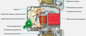
Operating principle of motor protection circuit breaker
The electromagnetic release is made in the form of a solenoid coil, inside of which there is a steel core with a return spring. Under the influence of an electric short circuit, the core is drawn into the coil, overcoming the resistance of the spring and acts on the release mechanism, as a result of which the contacts open.
The operating principle of thermal releases of the machine is the same as that of thermal relays. There is a bimetallic strip consisting of two plates, which are made of materials with different coefficients of thermal expansion. Under the influence of high temperature, resulting from the passage of a current exceeding the rated one, the plate begins to bend, put pressure on the release mechanism and, under the action of the spring, the contacts open, thereby de-energizing the circuit.
Immediately after the protection is triggered, it will not be possible to turn on the machine again, thus ensuring a time delay for cooling the engine after its emergency stop.
The response setpoint is set using the rotary regulator on the front part.
The required setting current is set by rotating the regulator until the desired current value on the scale aligns with the mark on the housing.
Connection to electric motor
To ensure safe operation, it is advisable to install a circuit breaker in front of the frequency converter. Moreover, a three-phase network requires a three-phase machine, and not three separate single-phase ones. This will allow you to quickly turn off all phases at once, both in case of wiring overload and in case of imbalance in one of the phases. The rating of the machines is selected based on the load current.
Connecting the neutral and grounding conductors is mandatory. They are pulled directly from the corresponding tires using a wire of the required cross-section. To protect people and monitor the state of insulation, it is advisable to add another RCD (residual current device) to the circuit. It is turned on in front of the machine. If a leakage current occurs, the RCD will simultaneously break the phases and zero, completely de-energizing the circuit.
The circuit is developed depending on the purpose of the device with which the electric motor operates.
When purchasing cheap converter models, for starting and stopping, you may need to install a special relay that fixes the contacts in the desired position. In this case, from the output of the machine, the wires are fed to the relay, and from its output they go to the frequency converter. The motors themselves are connected to the inverter directly.
Connection diagram of a frequency converter for two electric motors
As you know, asynchronous motors can operate with both single-phase and three-phase voltage. Before connecting the motor to the frequency converter, you need to check how the windings are connected. They should be:
- “star” - if the voltage at the inverter output is three-phase;
- “triangle” - if the converter supplies single-phase power.
Frequency converter for electric motor: direct connection is not possible for all motors
The frequency converter for the electric motor is connected using cables (not wires), the cross-section and parameters of which correspond to the parameters of the device. This data, as well as recommendations for connection, should be in the device passport. So read the manual carefully. This can save you from a lot of trouble. Still, there may be peculiarities.
Advantages of modular devices
We are talking about features that allow rational, full use of equipment. Including:
- Save working time by reducing the established time frame for installation and dismantling work.
- Comprehensive coverage of the manufacturing and household electrical market sectors.
- Different operating currents.
- Competitive price of products.
- Double body protection.
- Indication of the status of the main contacts.
Note! Manufacturers have established clamp designs that provide tight contact for conductors and busbars.
Access for sealing elements is also provided.
Firstly
For reasons of safe operation of the device, when connecting a frequency generator (or any other device) to the power supply, it is imperative to install a circuit breaker. The machine is installed in front of the frequency switch.
Moreover, if the frequency converter is connected to a network with three-phase voltage, then it is necessary to install a machine that is also three-phase, but with a common shutdown lever. This will allow you to turn off power from all phases simultaneously if there is a short circuit or severe overload on at least one phase.
If the frequency converter is connected to a network with single-phase voltage, then a single-phase machine is used. But at the same time, the current of one phase is taken into account, multiplied by three.
When connecting a three-phase machine, its operating current is determined by the current of one phase.
It is definitely forbidden to install a circuit breaker into the gap of the neutral cable, both with a single-phase connection and with a three-phase one.
Such a connection only looks identical in appearance (it is a mistake to understand that there is only one circuit and it does not matter where it is broken). In fact, in the event of a break in the phase cables, when the machine is triggered, the power is completely turned off and there will be no phases on the device circuits at all
It is safe. And when the machine with a broken zero is triggered, the operation of the device will stop. But at the same time, the motor windings and frequency circuits will remain energized, which is a violation of safety regulations and is dangerous for humans.
Also, under no circumstances does the grounding cable break. Like the zero, they must be connected to the corresponding buses directly.
Selection method
To correctly select the rating of a thermal relay, we need to know its In (operating, rated current) and, based on this data, we can select the correct setting range of the device.
The technical operation rules of the Electrical Installation Code stipulate this point and it is allowed to set up to 125% of the rated current in explosion-proof rooms, and 100%, i.e. not higher than the motor rating in explosive areas.
How to find out In? This value can be found in the electric motor’s passport or in the plate on the housing.
As you can see on the plate (click on the picture to enlarge) two ratings are indicated: 4.9A/2.8A for 220V and 380V. According to our connection diagram, you need to select the amperage, focusing on the voltage, and according to the table, select a relay to protect the electric motor with the desired range.
For example, let's look at how to choose thermal protection for an AIR 80 asynchronous motor with a power of 1.1 kW, connected to a three-phase 380 volt network. In this case, our In will be 2.8A, and the permissible maximum current of the “heater” will be 3.5A (125% of In). According to the catalog, RTL 1008-2 with an adjustable range of 2.5 to 4 A is suitable for us.
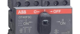
APD25, APD80 | Contactors and starters | Low voltage equipment
Purpose.
The automatic starter APD25, APD80 of an alternating current electric motor is designed to protect against overload, phase loss, short circuit of a three-phase asynchronous motor, and also as a starter for infrequent switching in a circuit with a current of 0.1 to 80 A and a voltage of up to 690 V. It is also Can be used as distribution line protector, load transfer device and disconnector.
Specifications.
- maximum rated current Inom.max (A): 25, 80. - rated operating voltage Unom (V): 230 (240), 400 (415), 440, 500, 690. - rated insulation voltage Ui (V): 690.- rated frequency (Hz): 50/60.- degree of protection of the shell: IP20.- rated impulse withstand voltage Uimp (V): 8000.- ambient temperature: from -5°C to +40°C.- relative air humidity: no more than 90% (at 25°C ± 5°C). - installation altitude: no more than 2000 m above sea level - angle between the installation surface and the vertical plane: no more than 30°. - permissible shock load (sinusoidal impulse): 30 g (6 ms). - permissible vibration intensity: 5~150 Hz, 5 g. - design operating mode: continuous operation - warranty period 2 years
Operating principle and design features.
The automatic starter of the APD25, APD80 series of AC electric motor combines the functions of a disconnector, circuit breaker and thermal relay in one electronic device with the functions of insulation, overload protection, temperature compensation, phase loss protection, short circuit protection.
IEC60947-2 and IEC60947-4-1 of the International Electrotechnical Commission.
Specifications.
Table 1. Technical characteristics and operating modes of automatic engine starters of the APD25, APD80 series.
| Automatic engine starter type | APD25 | APD80 |
| Type of current | Variable, 50, 60 Hz | |
| Maximum rated current, A | 25 | 80 |
| Rated operating voltage, V | 230, 400, 440, 500, 690 | |
| Rated insulation voltage, V | 690 | |
| Switching wear resistance, VO cycles | 2000 | |
| Mechanical wear resistance, VO cycles | 10000 | |
| Main application category | AS-3 | |
| Type of climate control and placement category | U3 | |
| Degree of protection | IP20 | |
Symbol structure
Schematic electrical diagram.
Table 2. Rated current of the automatic motor starter and power of the electric motor controlled by the ADF.
| No. | Rated currentIn, A | Rated operating current (*), A | Standard rated power of a three-phase electric motor, kW | |||||
| AS-3, 50/60 Hz | ||||||||
| 230/240 V | 400 V | 415 V | 440 V | 500 V | 690 V | |||
| 1 | 0,16 | 0,1–0,16 | — | — | — | — | — | — |
| 2 | 0,25 | 0,16–0,25 | — | — | — | — | — | — |
| 3 | 0,4 | 0,25–0,4 | — | — | — | — | — | — |
| 4 | 0,63 | 0,4–0,63 | — | — | — | — | — | 0,37 |
| 5 | 1 | 0,63–1 | — | — | — | 0,37 | 0,37 | 0,55 |
| 6 | 1,6 | 1–1,6 | — | 0,37 | — | 0,55 | 0,75 | 1,1 |
| 7 | 2,5 | 1,6–2,5 | 0,37 | 0,75 | 0,75 | 1,1 | 1,1 | 1,5 |
| 8 | 4 | 2,5–4 | 0,75 | 1,5 | 1,5 | 1,5 | 2,2 | 3 |
| 9 | 6,3 | 4–6,3 | 1,1 | 2,2 | 2,2 | 3 | 3,7 | 4 |
| 10 | 10 | 6–10 | 2,2 | 4 | 4 | 4 | 5,5 | 7,5 |
| 11 | 14 | 9–14 | 3 | 5,5 | 5,5 | 7,5 | 7,5 | 9 |
| 12 | 18 | 13–18 | 4 | 7,5 | 9 | 9 | 9 | 11 |
| 13 | 23 | 17–23 | 5,5 | 11 | 11 | 11 | 11 | 15 |
| 14 | 25 | 20–25 | 5,5 | 11 | 11 | 11 | 15 | 18,5 |
| (*) – range of regulation of thermoelement current setting. | ||||||||
Table 3. Technical characteristics of the automatic engine starter and its short circuit breaking capacity.
| No. | Rated currentIn, A | Rated operating current (*), A | Ultimate short-circuit breaking capacity, rated short-circuit breaking capacity | Discharge distance(mm) | |||||||||
| 230 / 240 V | 400 / 415 V | 440 V | 500 V | 690 V | |||||||||
| Icu kA | Ics%Icu | Icuka | Ics%Icu | Icuka | Ics%Icu | Icuka | Ics%Icu | Icuka | Ics%Icu | ||||
| 1 | 0,16 | 0,1–0,16 | 100 | 100 | 100 | 100 | 100 | 100 | 100 | 100 | 100 | 100 | 40 |
| 2 | 0,25 | 0,16–0,25 | 100 | 100 | 100 | 100 | 100 | 100 | 100 | 100 | 100 | 100 | |
| 3 | 0,4 | 0,25–0,4 | 100 | 100 | 100 | 100 | 100 | 100 | 100 | 100 | 100 | 100 | |
| 4 | 0,63 | 0,4–0,63 | 100 | 100 | 100 | 100 | 100 | 100 | 100 | 100 | 100 | 100 | |
| 5 | 1 | 0,63–1 | 100 | 100 | 100 | 100 | 100 | 100 | 100 | 100 | 100 | 100 | |
| 6 | 1,6 | 1–1,6 | 100 | 100 | 100 | 100 | 100 | 100 | 100 | 100 | 100 | 100 | |
| 7 | 2,5 | 1,6–2,5 | 100 | 100 | 100 | 100 | 100 | 100 | 100 | 100 | 3 | 75 | |
| 8 | 4 | 2,5–4 | 100 | 100 | 100 | 100 | 100 | 100 | 100 | 100 | 3 | 75 | |
| 9 | 6,3 | 4–6,3 | 100 | 100 | 100 | 100 | 50 | 100 | 50 | 100 | 3 | 75 | |
| 10 | 10 | 6–10 | 100 | 100 | 100 | 100 | 15 | 100 | 10 | 100 | 3 | 75 | |
| 11 | 14 | 9–14 | 100 | 100 | 15 | 50 | 8 | 50 | 6 | 75 | 3 | 75 | |
| 12 | 18 | 13–18 | 100 | 100 | 15 | 50 | 8 | 50 | 6 | 75 | 3 | 75 | |
| 13 | 23 | 17–23 | 50 | 100 | 15 | 40 | 6 | 50 | 4 | 75 | 3 | 75 | |
| 14 | 25 | 20–25 | 50 | 100 | 15 | 40 | 6 | 50 | 4 | 75 | 3 | 75 | |
Overall and installation dimensions.
Additional components for APD25.
| Undervoltage releases | ||
| APD25-RMN 110V-127V 50Hz | APD25-RMN 220V-240V 50Hz | APD25-RMN 380V-415V 50Hz |
| Remote releases (shunt) | ||
| APD25-RD 110V-127V 50Hz | APD25-RD 220V-240V 50Hz | APD25-RD 380V-415V 50Hz |
| Additional contacts | ||
| APD25-DK-11 (1р+1з) | APD25-DK-20 (2р) | |
| Additional contacts with fault indication | ||
| APD25-DKI-0101 (1z+1z) | APD25-DKI-0110 (1z+1r) | APD25-DKI-1001 (1р+1з) |
| APD25-DKI-1010 (1r+1r) | ||
| Additional contact attachment | ||
| APD25-PDK-11 (1р+1з) | APD25-PDK-20 (2р) | |
| Boxing protective | ||
| APD25-Boxing protective IP55 | ||
undervoltage releases
www.etk-oniks.ru
Features of protection of electric motors in industrial conditions
Often, when turning on devices whose power exceeds 100 kW, the voltage in the general network drops below the minimum. In this case, the working power units are not switched off, but their speed is reduced. When the voltage is restored to normal levels, the motor begins to gain speed again. In this case, its operation occurs in overload mode. This is called self-starting.
Self-starting sometimes causes false alarms. This can happen when, before the temporary voltage drop, the installation had been operating in normal mode for a long time, and the bimetallic plate had time to warm up. In this case, the thermal release sometimes trips before the voltage returns to normal. An example of a voltage drop in a car's electrical network in the following video:
To prevent the shutdown of powerful factory electric motors during self-starting, relay protection is used, in which current transformers are connected to the general network. Protective relays are connected to their secondary windings. These systems are selected using complex calculations. We will not present them here, since in production this task is performed by full-time power engineers.
Select and calculate an automatic machine for an electric motor
There are two common ways to select a switch for an engine.
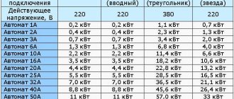
So, the first way is to calculate the total power of the devices that will be powered by this switch. We calculate what kind of devices (TV, refrigerator, computer, washing machine, etc.) will be connected to this electric current circuit, add up the power of all these devices and, based on this, calculate the current of the outlet group. When making such calculations, you should take into account how many phases there are in your grown electric motor. For example, in three-phase, with a power of 4 kW, 4 ∙ 3 = 12A, which means 12A is the operating current. This means that a 16A automatic machine will fit such an electric motor.
The second way to calculate the maximum power of devices connected to the machine is to calculate the total power through the passports of each device. The power ratings of the devices indicate the power, so we add it up and determine the total power. As an example, 2kW + 600W + 2100W = 4700W. Now we simply substitute the value into the generally accepted formula: I=W/U, where I is power, W is voltage and U is current in the network; I = 4700 divided by 220, so we get 21.36A. But do not forget that washing machines and some other appliances have their own motors, and they have a so-called starting current, which, when started, is much greater than the indicated power of the appliance. But manufacturers of automatic machines know this very well and therefore there is a current setting on the switches.
Selecting a machine is not so difficult, guided by the following rules:
Modern electrical protection devices for power units
Modular automatic motors, which are universal devices that successfully cope with all the functions described above, are very popular.
In addition, they can be used to adjust shutdown parameters with high accuracy.
Modern automatic motors come in many varieties, differing from each other in appearance, characteristics and control method. As when selecting a conventional device, you need to know the value of the starting current, as well as the rated current. In addition, it is necessary to decide what functions the protective device should perform. Having made the necessary calculations, you can buy an automatic motor. The price of these devices directly depends on their capabilities and the power of the electric motor.
Connection
To clarify the characteristics and availability of the product, or to receive a free consultation, contact the operator at the specified multi-channel phone number. If you can’t contact yourself, leave your contact details: they will call you back.
Specialists will talk about the capabilities of each Eaton (Moeller) motor switch product and inform you about new product arrivals. If necessary, they will connect you with the sales department or manager. Correspondence with clients is carried out by email.
Modern electrical protection of engines
In the electrical equipment market, electric motor protection with the help of universal protective devices, the so-called automatic motors, which perform all the above protective functions, is gaining increasing popularity. These devices have a modular design and are mounted on a DIN rail and control the operation of power contactors. In addition to the above functions, some automatic motors allow you to precisely adjust various safety shutdown parameters.
Automatic motor with sensors - current coils
There are many varieties of modern automatic motors, which differ in switching power, set of functions, control method, connection diagram and appearance. To select the appropriate protective device for a particular motor, you need to know its rated and starting current parameters, and you also need to determine the required set of protective functions and options.
The cost of automatic motors is directly proportional to the power of the electric motor and functional protective capabilities. The world leaders in the production of motor protective circuit breakers are the following well-known brands: Schneider Electric, ABB, IEK, Novatek electro, and others.
Variety of motor protection devices available on the market
The motor protection circuit breaker (universal unit) shown in the figure below allows you to configure the rated and starting current of the electric motor, permissible voltage thresholds, and can monitor the mechanical load on the electric motor shaft. The quality of insulation of the electric motor windings is also monitored with the ability to set a ban on switching on.
Continuous monitoring of multiple operating parameters helps extend the life of the engine and driven equipment. A special additional information exchange unit allows you to connect the device to automatic control systems.
Universal protection block
Automatic activation of the backup engine using a soft starter
Soft starting and braking devices are devices that allow you to limit starting currents, perform a smooth stop of the engine, and also include motor protection functions. At low powers there is no point in installing these devices; you can get by with a starter.
Today we will talk about automatically starting a backup engine when the working engine stops. Of course, high-power motors that need to be turned on using soft starters.
Let's assume we have two fans. One of them is working, the second is a reserve one, which turns on automatically if the main fan fails.
First you need to choose a manufacturer of soft starters. I settled on Schneider Electric. Why Schneider Electric? Because I managed to get all the necessary documentation for it, including the user manual. Having the necessary information in hand, you can begin to build a diagram. To make a circuit correctly, you need to know how this device works.
We will use the Altistart 22 series.
First I want to give you a diagram from the user manual.
Altistart 22 in the motor supply circuit
This circuit allows you to start, stop and protect one three-phase asynchronous electric motor. I took this diagram as a basis. It is also called a two-wire control circuit. I simplified it a little, threw out the “unnecessary” elements and got a control circuit for two engines, in which the backup engine is turned on if a worker fails.
Scheme for automatically switching on a backup engine
So, let's look at the resulting diagram in detail.
Cam switch SA1 indicates which engine will be working and which will be standby. Before starting work, we set the SA1 switch to the position we need. The diagram in better quality can be downloaded here. The switch program for switch SA1 is also presented there.
Cam switch SA2 is used to enable (disable) automatic mode, i.e. when switched off, in the event of an accident, the second engine will not start. You will have to turn on the backup engine manually.
The SB push-button station is used to start, stop and signal engine operation. It consists of a button with two normally open contacts and two signal lamps. The button must be locked! If the working engine is running, HL1 lights up, but if the backup engine is running, HL2 lights up.
To implement the automatic switching on of the backup motor, I used the internal relay R2 of the soft starter, which turns off due to a malfunction.
Contactors KM1 and KM2 are used to disconnect the power load in the event of an accident. In the event of an accident, contact R2A-R2C opens and the contactor is switched off, R2B-R2C turns on the backup motor.
For a better understanding of the operation of Altistart 22, I will also provide a diagram of operation with two-wire control.
Timing diagram of engine operation
As we can see from the diagram, the engine will be in working condition if the contactor KM1 (KM2) turns on, i.e. power will be supplied to the soft starter and the S1 button is pressed. Button S1 supplies +24V voltage to input LI2.
It is also worth noting that signal lamps must be designed for a voltage of 24V and consume a current of no more than 30mA, and preferably 15-20mA (according to the catalog, this is approximately how much it consumes). The fact is that the internal 24V power supply is limited to a current of 42mA. 8mA is required for digital input LI2. If it is impossible to connect the signal lamp in this way, the circuit will become a little more complicated.
And now the most interesting part
There is a small error in this diagram that is very easy to fix. Find...write, and I will also be interested in your opinion on this scheme, possible alternative solutions to this problem.