From the point of view of regulating the rotation speed of electric motors, the equation for electromechanical characteristics corresponding to Kirchhoff’s Second Law is interesting:
ω = U/C×Φ – ΥЯ /( C×Φ)3×M
When describing the technical characteristics of an electric motor, the speed expressed in revolutions per minute is often called the rotational speed ν according to the well-known relationship:
ω = 2p/T = 2pn
Therefore, these two different quantities are often used in the same sense. The speed w (frequency ν ) is directly dependent on the supply voltage U and inversely dependent on the magnetic flux Ф. Based on the above formula, the conclusion arises that the speed can be controlled by adjusting the armature resistance, magnetic flux and supply voltage.
Operating principle.
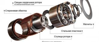
The operation of this motor directly depends on the interaction of the magnetic fields of the stator and collector. As you and I already know, there are windings in the stator and on the collector. If voltage is applied to these windings, magnetic fields will be created due to this. And these magnetic fields will force the collector to rotate. See how it is shown in the picture.
Regulating the speed of electric motors
About 70% of the power consumed by industry comes from electric drives. A huge variety of technological processes dictates its own rules, as a result of which there is a need to change the rotation speed of the electric motor directly during the technological process. In this article we will reveal various ways to control the rotation speed of electric motors.
Parameters by changing which we will change the speed of the alternating current motor (ACM):
- voltage frequency;
- number of pole pairs;
- voltage value;
- additional resistance in the rotor circuit;
- valve cascade.
Changeable parameters for DPT:
- supply voltage;
- armature winding circuit resistance;
- magnetic flux.
Methods for regulating the speed of an electric motor
Next we will look in detail at these methods and their applicability to various types of electric motors.
Frequency regulation
The most effective, constantly improving method. Application: AC motors (synchronous and asynchronous with short-circuit rotor). By adjusting the frequency of the supply voltage, we will change the angular velocity of the stator magnetic field, therefore, the speed of the motor in a significant range, having fairly rigid mechanical characteristics. To maintain normal power factor and allow short-term overloads, by changing the frequency, the value of the supply voltage itself should be changed.
Advantages of the method:
- wide range of adjustment;
- “rigidity” of mechanical characteristics;
- minimum “slip” and power losses.
The disadvantage is the high cost (in recent years it has become less relevant).
Regulation by changing the number of pole pairs
Application: because The industry does not mass-produce synchronous motors with a variable number of pole pairs; we will assume that the method is relevant only for asynchronous motors (hereinafter referred to as IM) with a short-circuit rotor. The method is implemented by changing the number of pole pairs of the windings. This can be achieved by making a motor with two independent windings. But this method leads to an increase in the cost of the design and an increase in the size of the machine. Therefore, it is most advantageous to increase the number of pole pairs without using a second independent winding. The industry produces two-speed, three-speed and four-speed electric motors.
Advantages:
- efficiency;
- “hard” mechanical characteristics.
Flaws:
- limited number of possible speeds;
- stepwise speed switching.
Changing the supply voltage
Application: asynchronous motors.
You can change the voltage on the stator by including resistors in its circuit (an old and uneconomical method), autotransformers or thyristor regulators. When regulating the speed by changing the voltage, the critical moment is proportional to the square of the supplied voltage. Resistance to short-term overloads and efficiency are reduced, so the method is preferable for “fan” loads. Another drawback is the small range of regulation.
Additional resistance in the rotor circuit
Application: IM with wound rotor. When the rotor resistance changes, the slip changes in direct proportion. But the magnitude of the critical moment remains constant. This allows you to select the resistance so as to equalize the critical torque with the starting torque, which has a beneficial effect on starting the engine under load.
Advantages of the method:
- ease of implementation;
- critical moment = const;
Flaws:
- large losses (when the speed changes, half the power is spent on heat generation);
- small range;
- “soft” mechanical characteristics.
Asynchronous valve cascade
Application: IM with wound rotor.
The meaning of regulation by cascade circuits is to supply additional EMF to the rotor circuit. By changing the additional EMF of the rotor, we change the rotor current, and therefore its torque and speed. In addition to the device of a valve cascade, a DFC (machine-valve cascade) can also create an additional EMF.
Advantages:
- Minimum associated power and contact equipment;
- smooth adjustments;
- low control power.
Flaws:
- price;
- low power factor;
- poor resistance to overloads.
Changing armature supply voltage
Application: any DPT. The method can be used if the source of electrical energy is a generator. It is impossible to implement from the general network.
Advantages:
- smooth adjustments;
- ease of starting and braking;
- efficiency.
Flaws:
- the need for threefold energy conversion→low efficiency;
- three electric machines in the system;
- expensive to operate.
Introduction of an additional resistor into the armature circuit
Application: any DPT.
It consists of sequential connection of an adjusting rheostat into the armature circuit. But the method has not become widespread due to its inefficiency and bad effect on engine efficiency, because A very large amount of energy is lost in the rheostat circuit.
Regulation by changing the magnetic flux
A rheostat is connected to the excitation circuit of parallel and mixed excitation motors. In series excitation machines, a change in the magnetic flux in the excitation winding is made by shunting this winding with an adjustable resistance. The maximum engine rotation speed is limited only by the mechanical strength of the armature. The engine speed is adjustable in the ranges of 2:1-5:1, in particular cases 8-10:1.
Advantages:
- minimal losses→profitability;
- wide range of regulation
Flaws:
- It is impossible to endlessly reduce the current in the field winding, the motor will go into overdrive.
To place an order, call the managers of the Kabel.RF® company by phone or send a request by email indicating the required electric motor model, purposes and operating conditions. The manager will help you choose the right brand, taking into account your wishes and needs.
Advantages and disadvantages.
Main advantages of DBT:
1. Simple engine design.
2. The shaft rotation speed can be changed very easily.
3. Due to the strong torque, very good starting characteristics.
4. Can be used both as a motor and as a generator.
5. Compared to some other engines, it is not large in size.
Flaws:
1. Very high price.
2. If you connect the motor to an alternating network, then rectifier devices are also needed.
3. Very often it is necessary to service the commutator-brush assembly.
4. The manifold has a limited service life due to wear.
Single channel motor controller
The device controls one motor, powered by voltage in the range from 2 to 12 volts.
Device design
The main design elements of the regulator are shown in the photo. 3. The device consists of five components: two variable resistance resistors with a resistance of 10 kOhm (No. 1) and 1 kOhm (No. 2), a transistor model KT815A (No. 3), a pair of two-section screw terminal blocks for the output for connecting a motor (No. 4) and input for connecting a battery (No. 5).
Note 1: Installation of screw terminal blocks is optional. Using a thin stranded mounting wire, you can connect the motor and power source directly.
Principle of operation
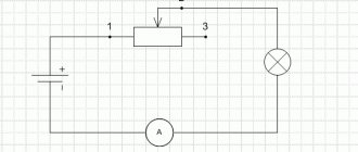
The operating procedure of the motor controller is described in the electrical diagram (Fig. 1). Taking into account the polarity, a constant voltage is supplied to the XT1 connector. The light bulb or motor is connected to the XT2 connector. A variable resistor R1 is turned on at the input; rotating its knob changes the potential at the middle output as opposed to the minus of the battery. Through current limiter R2, the middle output is connected to the base terminal of transistor VT1. In this case, the transistor is switched on according to a regular current circuit. The positive potential at the base output increases as the middle output moves upward from the smooth rotation of the variable resistor knob. There is an increase in current, which is due to a decrease in the resistance of the collector-emitter junction in transistor VT1. The potential will decrease if the situation is reversed.
Electrical circuit diagram
Materials and details
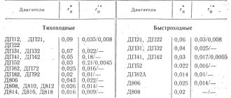
A printed circuit board measuring 20x30 mm is required, made of a fiberglass sheet foiled on one side (permissible thickness 1-1.5 mm). Table 1 provides a list of radio components.
Note 2. The variable resistor required for the device can be of any manufacture; it is important to comply with the current resistance values for it indicated in Table 1.
Note 3 . To regulate currents above 1.5A, the KT815G transistor is replaced with a more powerful KT972A (with a maximum current of 4A). In this case, the printed circuit board design does not need to be changed, since the distribution of pins for both transistors is identical.
Build process
For further work, you need to download the archive file located at the end of the article, unzip it and print it. The regulator drawing (termo1 file) is printed on glossy paper, and the installation drawing (montag1 file) is printed on a white office sheet (A4 format).
Next, the drawing of the circuit board (No. 1 in photo. 4) is glued to the current-carrying tracks on the opposite side of the printed circuit board (No. 2 in photo. 4). It is necessary to make holes (No. 3 in photo. 14) on the installation drawing in the mounting locations. The installation drawing is attached to the printed circuit board with dry glue, and the holes must match. Photo 5 shows the pinout of the KT815 transistor.
The input and output of terminal blocks-connectors are marked white. A voltage source is connected to the terminal block via a clip. A fully assembled single-channel regulator is shown in the photo. The power source (9 volt battery) is connected at the final stage of assembly. Now you can adjust the shaft rotation speed using the motor; to do this, you need to smoothly rotate the variable resistor adjustment knob.
To test the device, you need to print a disk drawing from the archive. Next, you need to paste this drawing (No. 1) onto thick and thin cardboard paper (No. 2). Then, using scissors, a disc is cut out (No. 3).
The resulting workpiece is turned over (No. 1) and a square of black electrical tape (No. 2) is attached to the center for better adhesion of the surface of the motor shaft to the disk. You need to make a hole (No. 3) as shown in the image. Then the disk is installed on the motor shaft and testing can begin. The single-channel motor controller is ready!
Application.
DC motors are widely used in various equipment. Such as: cranes, excavators, trams, electric trains, diesel locomotives, motor ships and so on. Also, such engines are used in power tools. In production, they can be found on machines where it is necessary to regulate the rotation speed over a very wide range.
That's all I have. The article was not very voluminous, but for the general concept it was quite informative. If you have questions, ask them in the comments, click on the social media buttons and subscribe to updates. Bye.
Sincerely, Alexander!
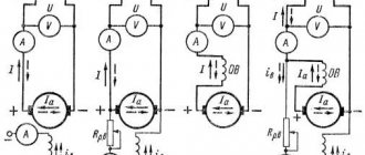
METHODS OF EXCITING DC MOTORS
Excitation of direct current (DC) electric motors refers to the effect of creating an EMF in them, which ensures rotation of the rotor. Their performance characteristics depend on how the field winding (OW) is connected in relation to the armature circuit.
The most common connection schemes are:
- with independent excitation (two windings are not connected to each other, and the OB is powered from a separate source);
- with parallel excitation or shunted type (in them the OB is connected parallel to the armature circuit);
- with sequential excitation (the OB is connected in series with the armature winding).
In a number of cases related to the operating characteristics of DC motors, a combined switching circuit is used.
Sometimes it is called “mixed” or “compound” (in it, a serial connection is combined with a parallel one). Let's consider each of the listed options in more detail.
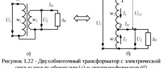
Independent arousal.
With this connection diagram, the field winding is not electrically connected to the armature coil (Fig. 1). To reduce heat losses and create the required EMF value, the number of turns in it is made large enough, which makes it possible to reduce the excitation current.
You can regulate the current in the armature using a resistor Rext connected in series. The rotation speed can be changed using resistor Rreg. The ability to independently control engine parameters is one of the advantages of this scheme.
Its disadvantage is the need to use an additional power source, which leads to increased material costs. The use of a circuit with independent excitation is determined by the design features of the controlled electric drive.
Parallel excitation.
The electrical connection circuit with parallel excitation generally resembles that discussed above. Its peculiarity is the presence of an electrical connection between the OB and the armature circuit (Fig. 2).
The operating efficiency of the two considered schemes is almost the same. The advantage of this connection method is that in this situation there is no need for an additional power source. Its disadvantage is the impossibility of separately adjusting the parameters of the electric motor.
Operating principle of an electric motor with sequential excitation.
A feature of this scheme is the sequential connection of the OB and the anchor chain (Fig. 3). With this connection option, the armature current is also the excitation current (Iа = Iв). This forces equipment manufacturers to wind the OB with wire of the same cross-section as that of the armature.
The disadvantage of this scheme is that the motor speed depends on the load on the shaft. As it increases, the voltage drop across the windings and the magnetic flux increase. And this leads to a strong drop in rotation speed. When the load decreases, the engine speed increases sharply and can reach dangerous values (it can start to peddle).
This option is used in cases where it is necessary to withstand a large starting force (torque). Or when the engine has to operate in short-term overload mode. Sequential starting circuits are used in traction motors (in subways, trams, electric locomotives and trolleybuses).
The principle of operation of a mixed-excitation motor.
Two windings are connected to each pole of the mixed-excitation system: serial and parallel (Fig. 4). They can be turned on in such a way that the magnetic fluxes are summed (consistent connection) or subtracted from one another (counter connection).
Depending on how the parts of each magnetic flux are related, a DC motor with mixed excitation approaches in its properties one of the previously discussed options.
Such schemes are used in situations where a large starting torque is required and at the same time it is impossible to do without adjusting the shaft speed under variable loads.
Two-channel motor controller
Used to independently control a pair of motors simultaneously. Power is supplied from a voltage ranging from 2 to 12 volts. The load current is rated up to 1.5A per channel.
Device design
The main components of the design are shown in photo.10 and include: two trimming resistors for adjusting the 2nd channel (No. 1) and the 1st channel (No. 2), three two-section screw terminal blocks for output to the 2nd motor (No. 3), for output to the 1st motor (No. 4) and for input (No. 5).
Note:1 Installation of screw terminal blocks is optional. Using a thin stranded mounting wire, you can connect the motor and power source directly.
Principle of operation
The circuit of a two-channel regulator is identical to the electrical circuit of a single-channel regulator. Consists of two parts (Fig. 2). The main difference: the variable resistance resistor is replaced with a trimming resistor. The rotation speed of the shafts is set in advance.
Note.2. To quickly adjust the rotation speed of the motors, the trimming resistors are replaced using a mounting wire with variable resistance resistors with the resistance values indicated in the diagram.
Materials and details
You will need a printed circuit board measuring 30x30 mm, made of a fiberglass sheet foiled on one side with a thickness of 1-1.5 mm. Table 2 provides a list of radio components.
Build process
After downloading the archive file located at the end of the article, you need to unzip it and print it. The regulator drawing for thermal transfer (termo2 file) is printed on glossy paper, and the installation drawing (montag2 file) is printed on a white office sheet (A4 format).
The circuit board drawing is glued to the current-carrying tracks on the opposite side of the printed circuit board. Form holes on the installation drawing in the mounting locations. The installation drawing is attached to the printed circuit board with dry glue, and the holes must match. The KT815 transistor is being pinned. To check, you need to temporarily connect inputs 1 and 2 with a mounting wire.
Any of the inputs is connected to the pole of the power source (a 9-volt battery is shown in the example). The negative of the power supply is attached to the center of the terminal block. It is important to remember: the black wire is “-” and the red wire is “+”.
The motors must be connected to two terminal blocks, and the desired speed must also be set. After successful testing, you need to remove the temporary connection of the inputs and install the device on the robot model. The two-channel motor controller is ready!
THE ARCHIVE contains the necessary diagrams and drawings for the work. The emitters of the transistors are marked with red arrows.
Source: servodroid.ru
Additional article READ