Asynchronous motors are widely used in modern energy. They are divided into several step options according to the number of phases - from one to five. In this article we will tell you in which systems two-phase motors are used, how they differ from others, and what operating principle is behind it all.
The electric motor has become a real revolution in energy. However, despite the fact that this technology is relatively young, today there are many types of electric motors in the field that are used everywhere - from heavy industry to private use. However, the most popular and widespread type was and is asynchronous motors. Combining high power, efficiency and efficiency, they are widely used in various industries - wood and metalworking, as pumps, in large factories and machine tools. Therefore, it is important to understand how an asynchronous motor works, what phases it has, and a two-phase stepper version will differ from a single- and three-phase one.
Operating principle
The principle of operation of an electric motor demonstrates the simplest experiment that we were all shown at school - the rotation of a frame with current in the field of a permanent magnet.
The frame with current is an analogue of the rotor, the stationary magnet is the stator. If current is applied to the frame, it will turn perpendicular to the direction of the magnetic field and freeze in this position. If you force the magnet to spin, the frame will rotate at the same speed , that is, synchronously with the magnet. We have a synchronous electric motor. But our magnet is a stator, and by definition it is motionless. How to make the magnetic field of a stationary stator rotate?
First, let's replace the permanent magnet with a current-carrying coil. This is the winding of our stator. As is known from the same school physics, a coil with current creates a magnetic field. The latter is proportional to the magnitude of the current, and the polarity depends on the direction of the current in the coil. If we apply alternating current to the coil, we get an alternating field.
Magnetic field is a vector quantity. The alternating current in the supply network has a sinusoidal shape.
A very clear analogy with a clock will help us. What vectors constantly rotate before our eyes? These are the hour hands . Let's imagine that there is a clock hanging in the corner of the room. The second hand rotates one full revolution per minute. An arrow is a vector of unit length.
The shadow that the arrow casts on the wall varies as a sine with a period of 1 minute, and the shadow cast on the floor changes as a cosine. Or a sine phase shifted by 90 degrees. But a vector is equal to the sum of its projections. In other words, the arrow is equal to the vector sum of its shadows.
Types of stepper motors according to the type of connection of stator electromagnets:
According to the type of connection of electromagnets, stepper motors are divided into: unipolar and bipolar.
The figure shows a simplified, schematic representation of the windings. In fact, each winding consists of several windings of electromagnets connected in series or parallel
- A bipolar motor has 4 terminals. Pins A and A feed winding AA, pins B and B feed winding BB. To turn on the electromagnet, a potential difference (two different levels) must be applied to the winding terminals, which is why the motor is called bipolar. The direction of the magnetic field depends on the polarity of the potentials at the terminals.
- A unipolar motor has 5 leads. The central points of its windings are connected to each other and are the common (fifth) terminal, which is usually connected to GND. To turn on the electromagnet, it is enough to apply a positive potential to one of the winding terminals, which is why the motor is called unipolar. The direction of the magnetic field depends on which winding terminal the positive potential is applied to.
- A 6-pin motor has taps from the center points of the windings, but winding AA is not connected to winding BB. If you do not use the terminals of the central points of the windings, then the motor will be bipolar, and if these terminals are connected and connected to GND, then the motor will be unipolar.
- The 8-pin motor is the most flexible in terms of connecting electromagnets. This motor can not only be used as bipolar or unipolar, but you can also determine for yourself how to connect the electromagnets of the windings, in series or in parallel.
Two-phase synchronous electric motor
Let's place two windings on the stator at an angle of 90 degrees, that is, mutually perpendicular. Let us supply them with sinusoidal alternating current. The phases of the currents will be shifted by 90 degrees . We have two mutually perpendicular vectors, varying according to a sinusoidal law with a phase shift of 90 degrees. The sum vector will rotate in a clockwise manner, making one complete revolution per period of the alternating current frequency.
We have a two-phase synchronous electric motor. Where can I get the phase-shifted currents to power the windings? Probably not everyone knows that in the beginning AC distribution networks were two-phase. And only later, not without a struggle, did they give way to three-phase ones. If we had not given in, our two-phase electric motor could have been connected directly to two phases.
But three-phase networks won, for which three-phase electric motors were developed. And two-phase electric motors have found their application in single-phase networks in the form of capacitor motors.
Three-phase synchronous motor
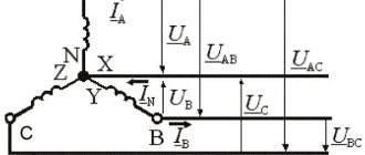
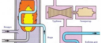
Modern AC distribution networks are made according to a three-phase circuit.
- Three sinusoids are transmitted over the network at once of a third of a period or 120 degrees relative to each other.
- A three-phase motor differs from a two-phase one in that it has not two, but three windings on the stator, rotated 120 degrees.
- Three coils connected to three phases create a total rotating magnetic field that turns the rotor.
How to determine the winding connection diagram?
Recognizing the winding method is quite simple. This can be done in two ways:
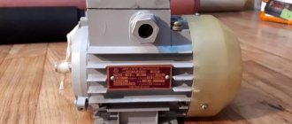
Look at the number plate on the engine. Usually it displays all the technical data relating to the operation of the engine. Among other things, you can find two symbols:
- geometric shape of a triangle;
- a star with three rays.
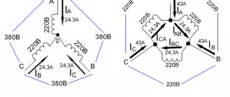
It is necessary to compare which of the symbols in the table is under the value 380V. It may look like this: 220/380V and next to them are the triangle/star symbols. This designation indicates that a star winding operates on a motor connected to a 380V network.
However, the engine does not always have such a sign. It may be missing or worn out. This determination method is more suitable for new engines that have not been repaired or serviced. It is better to check the old unit yourself. This will require a second method of recognizing the type of winding.
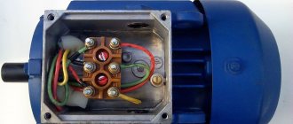
Unscrew the control unit and look at the terminal block. You can see 6 wire pins on it. Accordingly, there are 3 beginnings and three ends of the winding. Depending on the type of switching, these outputs can be referred to as the winding method:
- Star method. In this case, the three outputs are connected by one jumper. The three remaining inputs are connected to a separate phase one behind the other.
- Triangle method. Each two wire terminals are connected in series with jumpers. In this way the windings pass into each other. In this case, the power wires are connected to each input individually.
This method gives a complete picture of how the engine works and what circuit it is connected to. Knowing this, you can connect the motor to a 220V network.
INFORMATION: in rare cases, having unscrewed the control unit, you can find not 6 contacts in it, but only 3. This indicates that the switching circuit is located in the engine itself - under the protective casing on the end side.
Three-phase asynchronous motor
Current is supplied to the rotor of a synchronous motor from a power source. But we know from the same school physics that a current in a coil can be created by an alternating magnetic field. You can simply short the ends of the coil to the rotor. You can even leave just one turn, like in a frame. And let the current induce a rotating magnetic field of the stator.
- At the moment of start, the rotor is stationary, and the stator field rotates.
- The field in the rotor circuit changes, inducing an electric current.
- The rotor will begin to catch up with the stator field. But it will never catch up, since in this case the current will cease to be induced in it.
- In an asynchronous motor, the rotor always rotates slower than the magnetic field.
- The difference in speed is called slip. Connecting an asynchronous motor does not require current to be supplied to the rotor winding.
Synchronous and asynchronous motors have their own advantages and disadvantages, but the fact is that the majority of motors used in industry today are three-phase asynchronous motors.
Online electrical magazine
Purpose, design and principle of operation of single-phase asynchronous motors
Single-phase asynchronous motors are low-power machines that, in design, resemble similar three-phase electric motors with a squirrel-cage rotor.
Single-phase asynchronous motors differ from three-phase motors in the design of the stator, where in the grooves of the magnetic circuit there is a two-phase winding, consisting of a main, or working, phase with a phase zone of 120 el. hail and leads to terminals marked C1 and C2, and an auxiliary, or starting, phase with a phase zone of 60 el. hail and leads to terminals marked B1 and B2 (Fig. 1).
The magnetic axes of these phases of the winding are shifted relative to each other by an angle of 0 = 90 el. hail One working phase connected to an alternating voltage supply network cannot cause rotation of the rotor, because its current is excited by an alternating magnetic field with a fixed axis of symmetry, characterized by magnetic induction varying harmoniously with time.
Rice. 1. Connection diagram of a single-phase asynchronous motor with a squirrel-cage rotor.
This field can be represented by 2 components - similar radial magnetic fields of direct and reverse sequences, rotating with magnetic inductions, rotating in opposite directions at the same speed. But during the preparatory acceleration of the rotor in the desired direction, it continues to spin in the same direction when the operating phase is turned on.
For this reason, starting a single-phase motor begins with accelerating the rotor by pressing the start button, causing the excitation of currents in both phases of the stator winding, which are shifted in phase by an amount depending on the characteristics of the phase-shifting device Z, made in the form of a resistor, inductive coil or capacitor, and parts electronic circuits, which include the operating and starting phases of the stator winding. These currents induce a rotating magnetic field in the machine with magnetic induction in the air gap, which varies from time to time and uniformly within the boundaries of the largest and smallest values, and the end of its vector outlines an ellipse.
This. The elliptical rotating magnetic field finds EMF and currents in the conductors of the short-circuited winding of the rotor, which, interacting with this field, ensure acceleration of the rotor of a single-phase motor in the direction of rotation of the field, and within a few seconds it reaches almost rated speed.
Releasing the start button switches the electric motor from a two-phase mode to a single-phase one, which is then supported by a corresponding component of the alternating magnetic field, which, during its own rotation, slightly advances the spinning rotor due to slip.
Timely disconnection of the starting phase of the stator winding of a single-phase asynchronous motor from the supply network is necessary due to its design, which provides for a short-term operating mode - usually up to 3 s, which eliminates its long stay under load due to unacceptable overheating, insulation burning and failure.
An increase in the reliability of operation of single-phase asynchronous motors is ensured by integrating into the machine body a centrifugal switch with normally open contacts connected to terminals marked VTs and B2, and a thermal relay with similar contacts having terminals marked RT and C1 (Fig. 2, c, d).
The centrifugal switch automatically disconnects the starting phase of the stator winding connected to the terminals marked B1 and B2 when the rotor reaches a speed close to the nominal one, and the thermal relay disconnects both phases of the stator winding from the supply network when their heating is higher than permissible.
Changing the direction of rotation of the rotor is achieved by configuring the direction of the current in one of the phases of the stator winding at start-up by switching the start button and rearranging the iron plate on the electric motor terminals (Fig. 2, a, b) or only by rearranging 2 similar plates (Fig. 2, c , G).
Rice. 2. Marking of the phase terminals of the stator winding of a single-phase asynchronous motor with a squirrel-cage rotor and their connection for rotor rotation: a, c - right, b, d - left.
Comparison of technical features of single-phase and three-phase asynchronous motors
Single-phase asynchronous motors differ from three-phase machines with similar rated power by a reduced factor of the initial starting torque kп = Мп / Мн and an increased factor of the starting current ki = Mi / Мnom which for single-phase electric motors with a starting phase of the stator winding, which has an increased resistance to constant current and. The values of kп - 1.0 - 1.5 and ki = 5 - 9 have the lowest inductance than the working phase.
The starting properties of single-phase asynchronous motors are worse than those of three-phase asynchronous motors due to the fact that the elliptical rotating magnetic field excited when starting single-phase machines with the starting phase of the stator winding, equivalent to two unequal radial rotating magnetic fields - direct and reverse, causes a braking effect.
By selecting the characteristics of the parts of the electronic circuits of the operating and starting phases of the stator winding, it is possible to ensure the excitation of a radial rotating magnetic field at start-up, which can be the case with a phase-shifting element made in the form of a capacitor of appropriate capacity.
Because acceleration of the rotor causes a change in the characteristics of the machine circuits, the rotating magnetic field changes from radial to elliptical, thereby worsening the starting properties of the motor. Therefore, at a speed of about 0.8 rated, the starting phase of the stator winding of the electric motor is switched off manually or automatically, as a result of which the engine switches to a single-phase operating mode.
Single-phase asynchronous motors with a starting capacitor have a multiple of the initial starting torque kп = 1.7 - 2.4 and a multiple of the initial starting current ki = 3 - 5.
Two-phase asynchronous motors
In two-phase asynchronous motors, both phases of the stator winding with phase zones of 90 el. hail are workers. They are placed in the grooves of the stator magnetic circuit so that their magnetic axes form an angle of 90 el. hail These phases of the stator winding differ from each other not only in the number of turns, but also in rated voltages and currents, although at the rated mode of the motor their total powers are similar.
In one of the phases of the stator winding there is always a capacitor Cp (Fig. 3, a), which, in the conditions of the nominal mode of the motor, ensures the excitation of a radial rotating magnetic field. The capacity of this capacitor is determined by the formula:
Cр = I1sinφ1 / 2πfUn2
where I1 and φ1 are, respectively, the current and phase shift between the voltage and current of the stator winding phase circuit without a capacitor with a radial rotating magnetic field, I and U are, respectively, the frequency of the alternating current and the voltage of the supply network, n is the transformation ratio - the ratio of the effective numbers of winding phase turns stator, respectively, with and without a capacitor, determined by the formula
n = krev2 w2 / krev1 w1
where kob2 and kob1 are the winding coefficients of the corresponding phases of the stator winding with the number of turns w2 and w1.
The voltage at the terminals of the capacitor Uc, connected alternately with the winding phase of a stator-two-phase asynchronous motor, with a radial rotating magnetic field is higher than the network voltage U and is determined as follows:
Uc = U √1 + n2
The transition to a motor load that is different from the rated one is accompanied by a configuration of the rotating magnetic field, which becomes elliptical instead of radial. This aggravates the performance characteristics of the motor, and during start-up it reduces the initial starting torque to MP Mnom, thereby limiting the use of motors with a permanently switched on capacitor exclusively in installations with easy starting criteria.
To increase the initial starting torque, a starting capacitor Cn is connected in parallel with the working capacitor Cp (Fig. 3, b), the capacitance of which is much greater than the capacitance of the working capacitor and depends on the multiple of the initial starting torque, which can be increased to 2 or more.
Rice. 3. Schemes for connecting two-phase asynchronous motors with a squirrel-cage rotor: a - with a permanently connected capacitor, b - with working and starting capacitors.
After the rotor accelerates to a speed of 0.6 - 0.7 rated, the starting capacitor is turned off to avoid the transition of the radial rotating magnetic field to an elliptical one, which worsens the operating properties of the motor.
The starting mode of such capacitor engines is characterized by the following indicators: kп = 1.7 - 2.4 and ki = 4 - 6.
Capacitor motors have better energy performance than single-phase motors with a starting stator winding; their power factor, due to the use of capacitors, is higher than that of three-phase motors of similar power.
Universal asynchronous engines
In automatic control installations, universal asynchronous motors are used - low-power three-phase machines that are connected to a three-phase or single-phase network. When powered from a single-phase network, the starting and operating properties of the engines are somewhat worse than when used in three-phase mode.
Universal asynchronous motors of the UAD series are manufactured with two- and four-pole, which in three-phase mode have a rated power from 1.5 to 70 W, and in single-phase mode - from 1 to 55 W and operate from an alternating voltage network with a frequency of 50 Hz with efficiency η = 0 .09 - 0.65.
Single-phase asynchronous motors with split or shielded poles
In single-phase asynchronous motors with split or shielded poles, each pole is split by a deep groove into two unequal parts and carries a single-phase winding that covers the entire magnetic circuit of the pole, and short-circuited turns located on its smallest part.
The rotor of these engines has a short-circuited winding. Switching on the stator winding to a sinusoidal voltage is accompanied by the establishment of a current in it and the excitation of an alternating magnetic field with a fixed axis of symmetry, which induces the proper emf and currents in the short-circuited turns.
Under the influence of currents of short-circuited turns, the corresponding MD s excites a magnetic field that prevents the strengthening and weakening of the main magnetic field in shielded frequent poles. The magnetic fields of the shielded and unshielded parts of the poles are out of phase in time and, being displaced in space, form a resulting elliptical rotating magnetic field, moving in the direction from the magnetic axis of the unshielded part of the pole to the magnetic axis of its shielded part.
The interaction of this field with currents induced in the rotor winding causes the appearance of an initial starting torque Mn = (0.2 - 0.6) Mn and the acceleration of the rotor to the rated speed, if the braking torque applied to the motor shaft does not exceed the initial starting torque.
In order to increase the initial starting and maximum torques of single-phase asynchronous motors with split or shielded poles, magnetic shunts made of sheet steel are placed between their poles, which brings the rotating magnetic field closer to the radial one.
Shaded-pole motors are non-reversible devices that allow frequent starts, unexpected stops, and can remain in an inhibited state for a long time. They are manufactured with two- and four-pole rated power from 0.5 to 30 W, and with an improved design up to 300 W for operation from an alternating voltage network with a frequency of 50 Hz with an efficiency ηnom = 0.20 - 0.40.
Single-phase asynchronous electric motor
If we leave a short-circuited coil on the rotor and one coil on the stator, we will get an amazing design - an asynchronous single-phase motor.
At first glance, it seems that such an engine should not work. After all, there is no current in the rotor , and the magnetic field of the stator does not rotate. But if you push the rotor by hand in any direction, the engine will start! And it will rotate in the direction in which it was pushed at launch.
The operation of this motor can be explained by imagining the stationary alternating magnetic field of the stator as the sum of two fields rotating towards each other. While the rotor is stationary, these fields balance each other, so a single-phase asynchronous motor cannot start on its own. If the rotor is set in motion by an external force, it will rotate in parallel with one vector and towards the other.
A passing vector will pull the rotor along with it, a counter vector will slow it down.
It can be shown that due to the difference between the head and tail speeds, the influence of the tail vector will be stronger, and the engine will operate in asynchronous mode.
How to choose the right capacitors
Its switching diagram is assembled in such a way that in the first position all contacts are open, in the second two are closed: power and starting capacitors, and in the third - only power. The whole difference is that in bifilar single-phase motors the starting winding works only until the motor accelerates. Accordingly, the cross-section of the working winding wire is larger than that of the starting winding.
Now one bundle of wires, for example, with the number 1, will be the beginning, and the other will be the end. Active resistors, inductors and capacitors can be used for this. They even have labels that indicate that you can connect to both a three-phase network and a single-phase network. Using a tester, the wires are pinged to find the coils.
The working one has the lowest resistance, the average value is the starting winding, and the highest value is the common output; the resistance of two windings connected in series is measured.
But how to do it right? With an asymmetrical stator magnetic circuit A feature of motors with this design is the asymmetrical shape of the core, which is why pronounced poles appear.
The beginnings and ends of these windings are brought out into the BRNO box, the switching or distribution block for the beginning of the windings, and, as a rule, the engine passport is inserted into it: If the motor has two voltages, then there will be six terminals in the BRNO. To do this you will need two voltmeters.
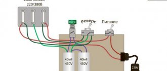
Let's look at the electric motor connection diagrams for both cases: Connection diagrams for the electric motor through a capacitor. How to connect a single-phase asynchronous motor with a starting winding to the network
We recommend: Phase zero measurement method
Connection diagram
It is possible to connect loads to a three-phase network using two circuits - star and delta. When connected by a star, the beginnings of the windings are connected to each other, and the ends are connected to the phases. When switched on in a triangle, the end of one winding is connected to the beginning of the other.
In a star connection circuit, the windings are under a phase voltage of 220 V; when connected in a delta, they are under a linear voltage of 380 V.
When switched on by a triangle, the motor develops not only more power, but also large starting currents. Therefore, sometimes they use a combined scheme - starting with a star, then switching to a triangle.
The direction of rotation is determined by the order in which the phases are connected. To change the direction, it is enough to swap any two phases.
How else can you connect an electric motor?
By connecting them to the circuit, the engine is launched, which should work correctly.
DC motors DPT The operating principle of such electric machines is based on Faraday's Law for magnetic induction.
Since during the starting process, especially under load, the current increases greatly, the capacitance of the starting capacitor should be three times greater than the operating capacitor. A magnetic field is created that interacts with the rotor winding and causes it to rotate. This is a contactor complemented by auxiliary mechanisms, for example, a thermal relay.
Wires from the windings are routed into it and secured to terminal blocks. Also note that connecting an electric motor with a power of 3 kW or more to conventional wiring is prohibited, as this can lead to the machines turning off or the plugs burning out. Therefore, it is worth considering the situation, for which you can simply reduce the capacity of the installed capacitor bank.
Of course, this is the simplest solution, but at the same time you will immediately receive a sharp reduction in the power of the electric motor. There are two options here: Nominal voltage 3xV - you're in luck and use the circuits above.
Using capacitors for DC voltage in AC networks is highly discouraged due to the fact that capacitors explode. In this case, the capacitance of the starting device will be in the μF range. Simply put, this current will only flow in the motor when it is fully loaded. Type of capacitors What capacitors are used when connecting an electric motor to a volt? As you can see, the voltage is distributed over two series-connected windings, where each is designed for such a voltage.
In this situation, the electric motors are connected correctly according to the star or delta circuit. The stator has special grooves in which the winding is placed, distributed in such a way that the angular distance is degrees. When it is necessary to turn off the power, K1 turns on. This is enough to start the electric motor; Worker, or nominal; Reloading.
It is necessary to look at the motor tag to see what voltage its windings are designed for; it is possible to connect the windings with a star and a triangle. In this situation, the electric motors are connected correctly according to the star or delta circuit. There are three wires sticking out of the electric motor. How to quickly and easily connect a three-phase motor to a single-phase DuMA8819 network
220 volt connection
Unlike a three-phase motor, a two-phase motor is initially designed to be connected to a single-phase network. To obtain a phase shift between the windings, a working capacitor is switched on, which is why two-phase motors are also called capacitor motors.
The capacity of the working capacitor is calculated using formulas for the nominal operating mode. But when the mode differs from the nominal one, for example, during startup, the balance of the windings is disrupted . To ensure the starting mode during start and acceleration, an additional starting capacitor is connected in parallel to the working one, which must be turned off when reaching the rated speed.
conclusions
Thus, asynchronous motors have carved out a strong niche in modern industry, offering many advantages at a relatively low cost of purchase and maintenance. However, it is worth noting that most systems primarily use universal three-phase motors, which can be freely converted into single-phase motors under certain system parameters.
Two-phase motors have their own niche, which they share with five-phase motors. Having different parameters and system features, they find their application in automatic devices, such as compensation or bridge systems. In addition, thanks to the ability to adjust a number of key parameters, such motors are easy to control and will heat up less. For example, it is possible to change the torque and rotation speeds through the voltage phases of the two windings. And craftsmen make such motors from a car generator.