To ensure proper operation of household appliances connected to the electrical network and ensure their safe operation, all connections must be made in accordance with the PUE. In electrical engineering, errors are not allowed; if the equipment is connected incorrectly, there is a risk that they will simply fail ahead of schedule, which can cause a malfunction of the entire system.
In this article we will look at the consequences of an incorrect connection and the correct procedure to avoid unforeseen situations.
Consequences of electricians' mistakes Source encom74.ru
How many volts are there in three phases?
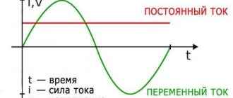
In a 1-phase network the voltage is 220 volts, in a 3-phase network between phase and zero it is also 220 volts, between 2 phases it is 380 volts.
Interesting materials:
How to determine the coordinate of a body during uneven movement? How to determine the coordinates of London? How to determine starch in potatoes using iodine? How to determine starch in kefir? How to identify dyes in wine? How to identify red fish with caviar? How to determine the magnification factor of a magnifying glass? How to determine the strength of the physique? How to identify corn starch? How to determine the climax?
What happens if you connect plus and minus?
Each of the plates holds its own charge, and if you confuse the minus and plus, then this makes your battery work in a different order - that is, a polarity reversal begins, so to speak - the minus elements want to become positive and vice versa!
Interesting materials:
What troops are included in the internal troops? What questions should you not ask a candidate during an interview? What issues does parliament decide? What questions are asked during an interview at the us embassy? What issues does Oblomov’s novel address? What kind of doctors are there at the military registration and enlistment office? What payments are due to children of war in 2022? What payments are due to a pensioner upon retirement? What payments are due to a pensioner upon voluntary dismissal? What payments are due to fire victims?
Causes of short circuit
A short circuit can occur for various reasons, the main one of which is a violation of the insulation or the relative position of live parts.
Very often, human or natural factors are to blame for the occurrence of short circuits. An example that women will appreciate (a miracle if they read this article) - due to constant kinks, the insulation deteriorates, and at one “wonderful” moment the hair dryer or iron “bangs” at the input or near the plug.
Another example is that due to mechanical failure or external influence, current-carrying parts for some reason end up too close to each other, even to the point of complete contact. This can happen due to natural phenomena (a tree fell on the wires), shocks, or falling electrical appliances.
Well, a classic example is a short circuit due to interference in the electrical wiring of home “jacks of all trades”. According to the laws of the genre, after this incident the master’s hair must stand on end and his face must be black. Such pictures don’t make me laugh – everything happens differently.
Connection diagrams for other types of lamps
To correctly connect other types of lighting devices, you must first know their operating principle and familiarize yourself with the connection diagram. Each type of lamp requires certain operating conditions. The filament filament process is not designed to emit light at all. In the area of high power and area, they have been noticeably replaced by gas-discharge devices.
Fluorescent lamps
In addition to incandescent lamps, both halogen and fluorescent tubular lamps (FL) are often used. The latter are common in administrative buildings, car painting bays, garages, industrial and retail premises. They are used a little less often at home, for example, in the kitchen to illuminate the work area.
The LL cannot be connected directly to a 220 V network; ignition requires high voltage, so a special circuit is used:
- choke, starter, capacitor (optional);
- electronic ballast.
The first scheme is used less and less often, it is characterized by lower efficiency, throttle hum and flickering of the light flux, which is often invisible to the eye. The electronic ballast connection is often shown on the housing.
Either one lamp or two are connected in series, depending on the situation and what is available, also with electronic ballast.
A capacitor between phase and zero is needed to compensate for the reactive power of the inductor and reduce the phase shift; the circuit will start without it.
Pay attention to how the lamps are connected; when lighting with fluorescent light, you cannot use the same rules as when working with incandescent lamps. The situation is similar with DRL and HPS lamps, but they are rarely found in everyday life, more often in industrial workshops and street lamps
Halogen light sources
This type is often used in spotlights on suspended and suspended ceilings. Suitable for lighting places with high humidity, as they are produced for operation in low-voltage circuits, for example, 12 volts.
A 50 Hz mains transformer is used for power supply, but the dimensions are large and over time it begins to hum. An electronic transformer is better suited for this; it receives 220 V with a frequency of 50 Hz, and leaves 12 V AC with a frequency of several tens of kHz. Otherwise, the connection is similar to incandescent lamps.
Video description
Earth instead of zero.
TN
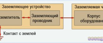
Exposed conductive parts are non-insulated areas of electrical installations that can be touched. During normal operation, no voltage is supplied to these areas of household electrical appliances. However, everything will be the other way around: if the insulation is destroyed, potential will appear on the body.
The causes of damage are mainly related to specific factors:
- aging technology;
- physical destruction;
- long service life at high speeds;
- accumulated dirt;
- humidity on the coating located near the body;
- climate influence;
- defect caused by the manufacturer.
Connecting old-style carbolite
Let's start with carbolite ones. This cartridge is collapsible and consists of three parts:
cylindrical body with thread
bottom
ceramic insert with contacts
Most often in our apartments we use cartridges marked:
E27
E14
The value in numbers indicates the diameter of the lamp base in millimeters that is suitable for this socket.
The letter “E” indicates that it belongs to the screw series with Edison threads.
There are also pin type, G series and some others presented below.
Such products are designed for a current of no more than 4A. That is, in a 220V network you can connect a load of up to 900W to them.
This is interesting: Armored copper cable 5*4 for entry into the house: load
Common problems and their solutions
If the neutral wire breaks, an emergency operation of the 3-phase network occurs. Due to the combustion of the working zero, in the case of unequal load, a very low or, conversely, high voltage is created on single-phase devices connected to this network, which exceeds the rated value characteristic of a single-phase circuit.
As a result, electrical equipment fails. This primarily applies to expensive electronic devices:
- computers;
- TVs;
- washing machines.
Such household appliances are most sensitive to fluctuations in the power supply voltage, especially to its increase.
Recommendations for troubleshooting
If there are two high potentials at the terminals of old-style sockets (2 phases and grounded zero - for new installation products with three contacts) - this situation requires urgent intervention. Since it is associated with a break in the neutral core, you first need to find the exact location of the damage using visual inspection methods plus the necessary tools. To do this, you will need to take actions depending on the nature of the damage.
When the problem affects all sockets in the residential premises of an entrance hall or a specific apartment, you should call an electrician who has access to the distribution cabinet and the input circuit breaker. If the malfunction is observed only in the apartment (on one/several distribution boxes or in a separate outlet), it is possible to fix it yourself. To do this you will need to perform the following operations:
- Turn off the input circuit breaker, located in the common corridor and supplying voltage to the entire apartment.
- Inspect the junction box, at the input of which or inside there is supposedly a fault hidden.
In order for the second phase to disappear from the sockets and the chandelier to start burning again, you will also need to isolate the damaged phase core from the already restored “zero”.
Only if you follow the appropriate instructions can you eliminate the detected fault observed in all, half or only one socket. The appearance of two phases, regardless of the total number of sockets involved, most often occurs when the rules for using household electrical products are violated.
Source: strojdvor.ru
Download
The same article, beautifully laid out and published in the paper magazine “Electrical Technical Market”:
• Short-circuit current: size matters / Article about short-circuit current, published in the magazine Elek.ru, pdf, 4.45 MB, downloaded: 604 times./
Respect and respect if you have read this far and intend to download books on this topic!
You are a serious person! • Shabad_M.A._Calculations_of_relay_protection_and_automation / Shabad M.A. Calculations of relay protection and automation. A good book from 1985, which tells about the design of electrical networks - from the equipment of substations to the selectivity of protective circuit breakers, pdf, 38.87 MB, downloaded: 1044 times./ • Belyaev A.V. Selection of equipment, protection and cables 0.4 kV / Belyaev A.V. Selection of equipment, protection and cables 0.4 kV - a book for the theoretical calculation of short circuit current. St. Petersburg 2008, pdf, 17.39 MB, downloaded: 812 times./ • RD 153-34.0-20.527-98 / Guidelines for calculating short circuit currents and choosing electrical equipment RD 153-34.0-20.527-98. The guidelines are intended for use by energy engineers when performing calculations of short circuit currents (SC) and testing electrical equipment (conductors and electrical apparatus) under the SC mode. MPEI, 1998, pdf, 3.61 MB, downloaded: 761 times./ • Electrical part of power plants and transformer substations / Electrical part of power plants and substations. Detailed description of circuits and calculations with examples. Tutorial. N.V. Kolomiets, Tomsk Polytechnic, 2007, pdf, 1.37 MB, downloaded: 704 times./ • Selection of electrical equipment and calculations of transformer substations / Selection of electrical equipment and calculations of medium and low voltage transformer substations. ABB, educational manual, pdf, 9.16 MB, downloaded: 660 times./ • Kharechko V.N., Kharechko Yu.V. Automatic switches of modular design / Kharechko V.N., Kharechko Yu.V.
Automatic circuit breakers of modular design: Reference manual. The reference manual sets out the requirements of GOST R 50345-99 (IEC 60898-95) for household circuit breakers intended for overcurrent protection, examines the design of circuit breakers, gives characteristics and their classification. Errors are analyzed that are partially corrected in the new version of GOST R 50345-2010, pdf, 7.17 MB, downloaded: 1062 times./ I look forward to questions and comments in the comments!
Short circuit of the neutral conductor to the phase conductor due to mechanical damage to the insulation.
A situation may arise when, when drilling a hole, screwing in a self-tapping screw, or hammering a nail into a wall, the electrical wiring is disrupted. In addition to this, damage to the wiring is accompanied by a short circuit, due to which the wire is damaged completely or partially. Such a malfunction is treated by opening the damage site and restoring the damaged section of the wire.
Sometimes with such a malfunction you can also observe two phases in the outlet. At the moment of closure, the phase and neutral conductors are welded together, and therefore the phase freely flows onto the neutral conductor. Moreover, even when the electrical equipment is turned off from the sockets and the lighting switches are turned off, the phase will be present on those sockets and switches that are supplied with voltage from this wire.
The malfunction is treated by restoring the damaged section of the wiring.
If you still have questions, then in addition to the article, watch the video, which also covers the topic of zero loss.
In this article, we examined only the most common faults that occur in a single-phase electrical network when the neutral wire is damaged. Now if two phases appear in your socket , you can easily identify and eliminate such a malfunction. Good luck!
Source: sesaga.ru
Additional information about finding the ground, phase, neutral wire
We remind you that we considered cases when there is no indicator screwdriver at hand, but there are current clamps and a multimeter. Then, before entering the apartment, they detect the ground, phase, neutral wire, and the home network is dialed. There are three cores, the technique is on the surface: between the phase and the other wire, the potential difference will be 230 volts. Please note that the technique is not suitable in other cases. For example, the voltage difference between two identical phase conductors is zero. It is difficult to measure and determine with a tester.
Let's add another method - it is prohibited by industry. A light bulb in a socket with two exposed wires. Using the tool, they find the phase; it is possible to short the core to ground. You cannot use water, gas, sewer pipes or other engineering structures. According to the rules, the cable antenna braid is equipped with grounding (grounding). In relation to it, it is permissible to use a tester (a light bulb in a socket prohibited by standards) to find the phase.
For determined people, we recommend fire escapes and steel tires for lightning rods. You need to clean the metal until it shines, call the phase phase. Please note that not all fire escapes are grounded (although they must be), lightning rod buses are 100%. If you discover such blatant arbitrariness, contact the management organizations; if there is no response, inform the government authorities. Indicate a violation of the rules for protective grounding of buildings.
Using special devices
Improvised methods do not always give reliable results, not to mention the danger of some of them to life. A much more reliable method is the use of measuring devices:
- Indicator screwdriver.
Inside its body there is a resistor connected to the light bulb. The presence of voltage is indicated by a light indication. This is the cheapest and most accessible method for a non-specialist: the device is commercially available and costs a little more than 30 rubles; - pocket tester
may also work . Before testing begins, the switch is set to AC mode. Only one probe is used (the second one can be left in your hand). If there is current, its value will be shown on the device screen; - Electrical installation safety data meter is a professional device that is designed to determine phase and phase-to-phase voltage, current strength and frequency, resistance, etc. Handling such a device requires special skills, so it is not recommended for non-specialists to purchase it.
Operating principles of RCD
From a technical point of view, any RCD is a high-speed switch. The operating principles of the residual current device are based on the response of the current sensor to the changing differential current flowing in the conductors. It is through these conductors that current is supplied to the electrical installation, which is protected by the RCD. A differential transformer is wound onto the toroidal core, which is a current sensor.
To determine the response threshold of an RCD having a certain current value, a highly sensitive magnetoelectric relay is used. The reliability of relay structures is considered quite high. In addition to relay ones, electronic device designs have now begun to appear. Here the threshold element is determined by a special electronic circuit.
How to connect an ordinary electric cartridge
To understand how to connect wires to the cartridge, you need to consider assembling the cartridge from scratch. This will be useful in case of cartridge repair. The brass central contact plate is pressed against the ceramic liner. Using a screw screwed into a steel plate located on the other side of the liner, the contact is installed on the liner.
The screw not only serves to secure the central contact, but also passes current through itself to this contact. It is not necessary to use a Grover, but it will be better if you install one. The screw must be tightened with sufficient force since current passes through it. Using the same principle, a second brass plate is installed. The central contact must be bent to the level of the side contacts.
Rings form on the conductors. Then they are threaded through the bottom and fixed to steel plates. If the cartridge is selected for connection through a standard switch, the phase should be connected to the central contact. Check how well the center pin fits. To check this, place the lamp base on the contact, making sure that while the base is touching the contacts, the central one bends by at least a few millimeters. If this is not the case, bend the contacts upward.
All that remains is to screw the body to the bottom. The socket is ready for use, all that remains is to select a lamp for it.
When is it 380 and when is it 220?
So why do we have a voltage of 220 V in our apartments and not 380? The fact is that, as a rule, consumers with a power of less than 10 kW are connected to one phase. This means that one phase and a neutral (zero) conductor are introduced into the house. This is exactly what happens in 99% of apartments and houses.
Single-phase electrical panel in the house. The right machine is introductory, then through the rooms. Who can find mistakes in the photo? Although, this shield is one big mistake...
However, if you plan to consume power more than 10 kW, then a three-phase input is better. And if you have equipment with three-phase power supply (containing three-phase motors), then I strongly recommend introducing a three-phase input into the house with a linear voltage of 380 V. This will save on wire cross-section, on safety, and on electricity.
Three-phase input. Input machine for 100 A, then - to a three-phase direct connection meter Mercury 230.
Despite the fact that there are ways to connect a three-phase load to a single-phase network, such modifications sharply reduce the efficiency of motors, and sometimes, all other things being equal, you can pay 2 times more for 220 V than for 380.
A little theory.
Without going into technical details, we can say that a single-phase electrical network is a method of transmitting electric current when alternating current flows to the consumer (load) through one wire, and returns from the consumer through another wire.
Let's take, for example, a closed
an electrical circuit consisting of an alternating voltage source, two wires and an incandescent lamp.
From the voltage source to the lamp, current flows through one wire and, having passed through the filament of the lamp, making it hot, the current returns to the voltage source through another wire. So, the wire through which current flows to the lamp is called phase
or simply
phase
(
L
), and the wire through which current returns from the lamp is called
zero
or simply
zero
(
N
).
When, for example, a phase wire breaks, the circuit opens, the flow of current stops and the lamp goes out. In this case, the section of the phase wire from the voltage source to the break point will be under current or phase voltage
(phase). The rest of the phase and neutral wires will be de-energized.
How and with what to determine phase and zero
To establish in a 2-phase network, where the phase is, where the zero is, the conductor of the light bulb is connected in turn to the wire that needs to be determined. This is done one by one with each core. For a 2-wire network, if during testing the light comes on when the ends touch, then the wire is phase, and the second is zero. In the case when the lamp does not light, it most likely means that no phase is detected here or there is no zero.
2 options for the development of events Source zen.yandex.ru
This option should not be excluded. A working electrical system is installed in a similar way, determining how correctly the electrical wiring is laid.
There is another method for determining the phase wire. To do this, the cable laid to the light bulb (control) is connected to some structure, like a precisely set zero. This could be a terminal in the electrical panel. If the other end comes into contact with a phase, the light will light up, which means the other conductor is neutral.
In a 3-wire electrical network, using a test lamp, you can establish which of the 3 conductors is zero, ground, phase.
To do this, connect the end of the wire connected to the control device with the lamp, in turn to the cable being tested. Here we will have to follow the principle of sequentially eliminating one thing after another. First, let's find the positions at which the light comes on, this means that one of the tested wires is phase, the other turns out to be zero.
Then we rearrange one of the contacts of the control lamp. Here you can fix 3 different options:
- The control lamp does not light up.
If the electrical network under test is equipped with an RCD or circuit breaker, these devices will trip. This position means only one thing: the free wire is the working phase wire, and those connected to the lamp are the neutral and grounding conductor.
Phase, zero, ground determined Source tehsistemy.ru
- After changing the position, the control lamp flashed.
In this position, the protective device or machine will immediately react, this will mean that the free cable is the working neutral, the ones being tested are the phase wire and grounding.
- There is no protection provided on the electrical circuit.
There is no protection provided on the electrical circuit.
The control lamp will light up in 2 positions. In order to establish the purpose of each of the 3 wires, it is necessary to disconnect the input cable connected to the ground loop in the electrical panel. Then, using the same meter with a lamp, all wires are checked, also sequentially eliminating one by one. If the lamp does not light up, then the grounding cable has been found.
In order to ring 3 conductors coming out of the wall, you will need an electrician's tools: an indicator screwdriver and a multimeter. Sequencing:
- Determine the phase on site using any available method.
- Locate the phase wire in the electrical panel or circuit breaker installed on the electric stove line of the stove or the entire kitchen.
- Disable protection by turning off the circuit breaker.
Just in case, before starting work, make sure there is no voltage on the disconnected power line.
- Repeat the procedure with the neutral wire and with the protective ground.
- Connect the phase conductor of the circuit breaker to zero to form a stable contact.
- Check with a multimeter set to the appropriate mode.
Zero break in the entrance panel of a house or apartment.
In the input panel of a house or apartment, the neutral wire may break at the input circuit breaker or at the neutral bus. As a rule, the screw connection becomes loose, causing contact between the wire and the clamp to be lost, or, in rare cases, the neutral wire breaks off at the clamp and hangs in the air.
Also, due to poor contact between the clamp and the wire, the wire heats up and burns and, as a result, a large transition resistance in the form of soot forms
, which gradually turns into a cliff.
If there is no zero, all electrical appliances in the house will not work. But if at least one household appliance remains plugged in or the light switch remains on, the phase through the radio components of the power supply
household appliances or
filament
will pass unhindered to the zero bus, and from the bus to all neutral wires of the electrical wiring. And as a result, there will be a phase on both sockets of sockets and contacts of switches. This is because all the neutral wires of the electrical wiring are connected together at the neutral bus.
To determine such a malfunction, it is enough to unplug all household appliances from the sockets and turn off all light switches or unscrew the light bulbs. After these actions, the second phase from the sockets and switch contacts will disappear. The malfunction is treated by restoring the contacts on the terminals of the input circuit breaker or on the zero bus.
Is it possible to connect a single-phase motor to 2 phases?
The Belarusian single-phase compressor is 220 V, so it doesn’t work in cold weather. Engine 2.2 kW. The garage has 380 volts.
Question about connecting the engine to 2 phases.
- Is there such a possibility at all?
- How to connect?
- Scheme?
- And how to check the connection with a tester (start-end)?
Comments and reviews
Check the capacitor - it may have lost capacity. A 2.2 kW "single-phase" motor is possible - maximum single-phase power for the motor. Then the active and reactive power diverge in phases. You can try to connect the windings to a common point, connecting it to the neutral, and connecting the free ends to two different phases.
I need to look at the stator. if the winding is made of two working and two starting windings, then the motor is 220 volts. But if the winding is made of 6 coils, then the capacitor is removed at 380 and connected to 3 phases.
You cannot supply two phases; it will work a little and it will burn out. You can make an autotransformer with a 380 V winding and remove 220 V from part of the winding. The power is about a kilowatt. And another option: if the engine is 220/380, which is very unlikely, turn it on with a star and supply 380 three phases.
In the USSR, a three-phase transformer 380/220 was produced. 1 kW will last for a short time, maybe on Avito.
If you feed 380 directly, the engine will most likely burn out.
you absolutely cannot connect a single-phase motor to 380 V, the whole point is that a single-phase motor has one working coil and one starting coil to which the capacitor is connected, most likely you have a low voltage
Most likely, judging by the power, this compressor is equipped with a standard three-phase asynchronous motor, the windings of which are connected by a “delta”; when operating from a single-phase network, a capacitor is used; to operate from a three-phase network, you need to connect the windings according to a “star” circuit; the capacitor is excluded from the circuit.
How to connect a socket to an electrical socket
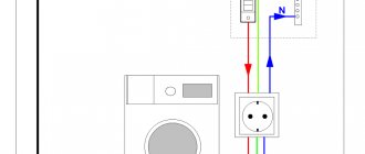
Sometimes there is a need to install an outlet, but the nearest distribution box is far away. I encountered such a case when I was renovating my bathroom. It was necessary to install an additional lamp near the mirror and provide the ability to connect electrical appliances, such as an electric razor.
A wall lamp – a ball – was already installed in the bathroom. I connected two more wires in parallel to the contacts in the electric socket and connected a socket to them in parallel. True, when the light in the bathroom is turned off, the outlet is also de-energized, but there is a positive side to this. In case of water leakage from the upper floor, there will be no short circuit even if water gets into the socket.
The socket in the bathroom or shower room should be installed as far as possible from the bath or shower to prevent splashing water. I installed a standard outlet and it has lasted over 17 years without any problems. Although it is better to install a sealed one, designed for rooms with high humidity.
Once again I had to connect to the electrical socket in the toilet room when installing an automatic light sensor and retrofitting the toilet with a bidet function.
In ancient times, when electricity bills were based on the number of light bulbs and sockets in an apartment, a device popularly known as the “rogue” was widely used.
The adapter cartridge that you see in the photo was screwed into the electric cartridge. On one side it has an external thread, like a light bulb, and on the other, an internal thread, like an ordinary socket. This crook had two brass tubes built into it, like a socket. The swindler allowed him to connect any electrical appliances to the chandelier. You can make such a crook yourself from an ordinary electric cartridge.
Magnetostriction effect
Since the field is variable, the core plates begin to compress and stretch in time with it. This process is called magnetostriction. Such movements are made with a high frequency of 100 Hz, with a current frequency of 50 Hz, vibration is emitted into space, which has an audio range and is distinguishable by the human ear. In addition to the standard frequency, alternating current contains higher frequency harmonics. There are more of them, the more the transformer is loaded, and this, in turn, is a sharper and more audible vibration. That's why the transformer hums.
Modern screwdrivers-indicators for determining phase, neutral wire, ground
When it is impossible to understand what color the wires are, it is useful to use an indicator screwdriver. The instructions for the battery-powered wonder say: you can use a probe to find the ground. We hasten to disappoint readers - any long conductor is identified falsely. A broken phase in the area of traffic jams, a neutral wire, a real ground - there is only one answer. Not every indicator screwdriver can perform functions equally effectively. The meaning of the operation is as follows:
- An active indicator screwdriver is capable of detecting a long conductor by emitting a signal there and catching a response.
- In practice, if the quality of the contacts is poor, the wave quickly fades. The indicator screwdriver shows the presence of ground on the open phase plug.
- To determine the ground, there is a condition - you need to touch the contact pad with your finger. This is the difference between active and passive indicator screwdrivers. In the first, it is possible to find the phase using this principle; in the second, the correct determination occurs provided there is no contact with this area.
A modern indicator screwdriver will allow you to judge from a distance whether current is flowing through the wire. There is a special remote mode. Usually there are even two: increased and decreased sensitivity. This will allow you to weed out the unused part of the wiring. Let's say there are known cases: builders introduced two phases into a house instead of one, and confused the places. Wiring must be used with great care.
I would like to note that in practice it is not easy to measure wiring resistance. It is much more convenient to determine the presence of a phase. There is no danger of burning the Chinese tester (this happens at times when trying to measure the resistance of a conductor under current). You should also know that low-resistance circuits are detected with error. For example, most testers do not give a zero scale when the probes are directly connected. But if you can’t determine the ground using an active indicator screwdriver, bad contacts are easy. If, with the plugs turned off, the light is on with your finger pressed to the contact pad, it’s time to think about buying a new automatic distribution box, replace the twists with modern caps.
For those frequently involved in repairs, we recommend a way out: marking the wires. It is better to do it with printer ink, the colors are approximately the same:
- Red – phase.
- Blue – neutral wire.
- Yellow is earth.
Typically, water-soluble paint is difficult to wash off. It is permissible to mark the colors of electrical wires with printer colors. The above system is not alone, it is often encountered. We will find black color on sale. You can use it as you please. The designation of wires is done once and forever. It is easier to wash off the markings with concentrated acetic acid; those who intend to clean their hands will need the substance (it is not always easy in practice). Finally, try not to stain your clothes.
Source: VashTehnik.ru
This question sometimes arises among novice electricians or apartment owners who have a good command of a set of repair tools, but have not previously delved deeply into electrical wiring. And then the moment came when the socket stopped working or the light bulb in the chandelier stopped glowing, but you don’t want to call an electrician and have a great desire to do everything yourself.
In this case, the primary task of the home handyman is not to eliminate the malfunction that has arisen, as it seems at first glance, but to comply with electrical safety rules and eliminate the possibility of being exposed to electric current. For some reason, many people forget about this, neglecting their health.
All current-carrying parts of the wiring must be reliably insulated, and the socket contacts must be hidden deep into the housing so that they cannot be accidentally touched by open areas of the body. Even the mechanical design of the plug inserted into the socket is designed in such a way that holding both contacts with your hand and getting exposed to electric current is quite problematic.
In everyday life, we do not notice this and the habit of not paying attention to electricity has already developed in our minds, which can have a detrimental effect when carrying out repair work on electrical appliances. Therefore, learn the basic safety rules and be careful when handling electricity.
How household electrical wiring works
Electricity in a residential building comes from a transformer substation, which converts the high-voltage voltage of the industrial power grid to 380 volts. The secondary windings of the transformer are connected in a star configuration, when three terminals are connected to one common point “0”, and the remaining three are connected to terminals “A”, “B”, “C” (click on the figure to enlarge).
The “0” ends connected together are connected to the substation ground loop. Here the zero is split into;
- working zero, shown in blue in the picture;
- protective PE conductor (yellow-green line).
All newly built houses are created according to this scheme. It is called the TN-S system. Three phase wires and both of the listed zeros are connected to the input inside the house's switchboard.
In old buildings, there are still often cases of the absence of a PE conductor and a four- rather than five-wire circuit, which is designated by the index TN-C.
Phases and neutrals from the output winding of the transformer transformer are supplied by overhead wires or underground cables to the input switchboard of a multi-story building, forming a three-phase voltage system of 380/220 volts. It is distributed along the driveway panels. A single phase voltage of 220 volts is supplied inside the residential apartment (wires “A” and “O” are highlighted in the picture) and a protective conductor PE.
The last element may be missing if the old electrical wiring of the building is not reconstructed.
Thus, a “zero” in an apartment is a conductor connected to the ground circuit in a transformer substation and used to create a load from a “phase” connected to the opposite potential end of the winding at the transformer substation. Protective zero , also called a PE conductor, is excluded from the power supply circuit and is intended to eliminate the consequences of possible malfunctions and emergency situations in order to drain the resulting damage currents.
The loads in such a scheme are distributed evenly due to the fact that on each floor and risers, certain apartment panels are wired and connected to specific 220 volt lines inside the access distribution board.
The system of supplied voltages to the house and entrance is a uniform “star”, repeating all the vector characteristics of the transformer substation.
When all electrical appliances in the apartment are turned off, and there are no consumers in the sockets and voltage is supplied to the panel, then no current will flow in this circuit.
The sum of the currents of a three-phase network is added up according to the laws of vector graphics in the neutral wire, returning to the windings of the transformer substation with a value of I0, or as it is also called 3I0.
This is a working, optimal power supply system that has been proven over many years. But, like any technical device, breakdowns and malfunctions may occur. Most often they are associated with poor quality of contact connections or complete breakage of conductors in various places in the circuit.
What is accompanied by a wire break in zero or phase?
It’s not difficult to disconnect or simply forget to connect a conductor to some device inside the apartment. Such cases occur as often as burnouts of metal current conductors due to poor electrical contact and increased loads.
If the connection between any electrical receiver and the apartment panel is lost inside the apartment wiring, then this device will not work. And it doesn’t matter at all what is broken: the zero or phase circuit.
The same picture appears in the case when a conductor of any phase that supplies the in-house or access electrical panel breaks. All apartments connected to this line with a fault will stop receiving electricity.
In this case, in the other two chains, all electrical appliances will function normally, and the current of the working neutral conductor I0 is summed up from the two remaining components and will correspond to their value.
As you can see, all of the listed wire breaks are associated with a power outage from the apartment. They do not cause damage to household appliances. The most dangerous situation arises when the connection between the ground loop of the transformer substation and the middle point of connection of the loads of the in-house or entrance electrical panel disappears.
This situation can arise for various reasons, but most often it occurs during the work of teams of electricians who have a related specialty as tasters...
In this case, the path of currents through the working zero to the ground loop (A0, B0, C0) disappears. They begin to move along the external circuits AB, BC, CA to which a total voltage of 380 volts is connected.
The right side of the picture shows that the current IAB arose when the line voltage was connected to the series-connected loads Ra and R in two apartments. In this situation, one owner can economically turn off all electrical appliances, while the other can use them to the maximum.
As a result of the action of Ohm's law U=I∙R, on one panel panel there may be a very small voltage value, and on the second panel it may be close to the linear value of 380 volts. It will cause damage to the insulation, operation of electrical equipment at non-design currents, increased heating and breakdowns.
To prevent such cases, overvoltage protections are used, which are mounted inside the apartment panel or expensive electrical appliances: refrigerators, freezers and similar devices from well-known world manufacturers.
How to determine zero and phase in home wiring
When faults occur in the electrical network, most often home craftsmen use a cheap Chinese-made voltage indicator screwdriver, shown at the top of the picture.
It works on the principle of passing capacitive current through the operator’s body. For this purpose, the following are placed inside the dielectric housing:
- bare tip in the form of a screwdriver for connecting to the phase potential;
- a current-limiting resistor that reduces the amplitude of the passing current to a safe value;
- a neon light bulb, the glow of which when current flows indicates the presence of a phase potential in the area being tested;
- contact pad for creating a current circuit through the human body to ground potential.
To check the presence of a phase, qualified electricians use more expensive multifunction indicators in the form of screwdrivers with an LED, the glow of which is controlled by a transistor circuit powered by two built-in batteries that create a voltage of 3 volts.
In addition to determining the phase potential, such indicators are capable of performing other additional tasks. They do not have a contact pad that needs to be touched when taking measurements. More details about how various indicator screwdrivers are designed and work are described here: Indicators and voltage indicators.
A method for checking the presence and absence of voltage in the sockets of an ordinary socket using a simple indicator is shown in the photographs below.
The left photo clearly shows that the glow of the indicator light in daylight is difficult to see and therefore requires increased attention when working.
The contact at which the indicator lights up is the phase. At the working and protective zero, the neon light should not glow. Any reverse action of the indicator indicates a malfunction in the connection circuit.
When using such a screwdriver, you must pay attention to the integrity of the insulation and do not touch the exposed terminal of the indicator, which is energized.
The following photos show how to determine the voltage in the same outlet using an old tester operating in voltmeter mode.
The instrument arrow shows:
- 220 volts between phase and working zero;
- no potential difference between the working and protective zero;
- lack of voltage between phase and protective zero.
The last case is an exception. The arrow in a normal circuit should also show a voltage of 220 volts. But it is not in our socket for the reason that the old building has not yet gone through the stage of electrical wiring reconstruction, and the owner of the apartment, who carried out the last renovation, installed a PE conductor in his premises, but did not connect it to the grounding contacts of the sockets and the PE bus. apartment panel conductor.
This operation will be carried out after the building is converted from the TN-C to TN-CS system. When it is completed, the voltmeter needle will be in the position marked with the red line, showing 220 volts.
Several ways to determine phase and neutral wires: How to find phase and zero
Troubleshooting Features
Simply determining the presence or absence of voltage does not always accurately determine the state of the circuit. The presence of different switch positions can confuse the technician. For example, the picture below shows a typical case when, with the switch turned off, there will be no voltage on the phase wire of the lamp at point “K” even with a working circuit.
Therefore, when taking measurements and troubleshooting, you should carefully analyze all possible cases.
An example of step-by-step troubleshooting in a non-working chandelier using an indicator screwdriver is shown here: What to do if the chandelier does not work
Source: electric.info
Why is this “zero” wire needed? It would be possible, as before, not to bother, and simply connect one of the phases to one pin of the kettle plug, and connect the other pin of the kettle plug to the ground, as we did before, and the kettle would work normally. In general, as I understand it, this is how they did it in old Soviet houses: there only two wires enter the house from the substation - a phase wire and a ground wire.
In new houses (new buildings), apartments already have three wires: phase, ground and this “zero”. This is a more progressive option. This is a European standard. And it is correct to connect the phase to zero, and leave the ground alone, giving it only the role of protection against electric shock (this is exactly the meaning of the word “grounding”, and it should have nothing to do with current consumption in the socket). Because if everyone also sends current to the ground, then the grounding itself will become dangerous - it will become absurd, the whole meaning of grounding will be turned on its head.
Now a little mathematics, for those who know how to calculate it, and for those who are not yet tired: let's try to calculate the voltage between the phase and the “neutral” (the same as between the phase and “zero”). (here is another link with calculations, if anyone wants to bother with this) Let the voltage amplitude between each phase and the “neutral” be equal to U (the voltage itself is variable, and jumps along the sine line from minus amplitude to plus amplitude). Then the voltage between the two phases is equal to: U sin(a) - U sin(a + 120) = 2 U sin((-120)/2) cos((2a + 120)/2) = -√3 U cos(a + 60). That is, the voltage between the two phases is √3 (“square root of three”) times greater than the voltage between the phase and the “neutral”. Since our three-phase current at the substation has a voltage of 380 Volts between phases, the voltage between phase and zero is equal to 220 Volts. This is why we need “zero” - in order to always, under any conditions, under any loads in the network, have a voltage of 220 Volts - no more, no less. It is always constant, always 220 Volts, and you can be sure that as long as all the electrical equipment in the house is connected correctly, nothing will burn out. If there were no neutral wire, then with different loads on each of the phases, a so-called “phase imbalance” would arise, and something could burn out in someone’s apartment (possibly even in the literal sense of the word, causing a fire). For example, the wiring insulation could simply catch fire if it is not fireproof.
Until now, for simplicity, we have considered the case of an imaginary three-phase generator standing right in the apartment. Since the distance from the apartment to the yard substation is small, and you don’t have to save on wires, it is possible (and necessary, it’s also more convenient) to move this imaginary three-phase generator from the apartment to the substation. Mentally transferred. Now let's deal with the imaginary nature of the generator. It is clear that the real generator is not located at the substation, but somewhere far away, at the HydroElectro Station, outside the city. Can we at a substation, having three incoming phase wires from power lines, somehow connect them so that everything turns out the same as if the generator was standing right in this substation? We can, and here's how. In the yard substation, the three-phase voltage coming from the power line is reduced by a so-called “three-phase” transformer to 380 Volts on each phase. A three-phase transformer is, in the simplest case, just three ordinary transformers: one for each phase
In reality, its design was slightly improved, but the operating principle remained the same:
There are small and not very powerful ones, but there are large and powerful ones:
Thus, the incoming phase wires from the power lines are not directly connected and brought into the house, but go to this huge three-phase transformer (each phase to its own coil), from which, in a “contactless” way, through electromagnetic induction, they transmit electricity to three output coils , from which it goes through wires to a residential building. Since at the output of a three-phase transformer there are the same three phases that came out of the three-phase generator at the power plant, here one can connect one end (conventionally, “left”) of these three output coils of the transformer to each other in the same way to obtain a “neutral” "at your substation. And from the neutral - bring the fourth “neutral wire” into the residential building, along with three phase wires (coming from the conditionally “right” ends of these three output coils of the transformer). And also add a fifth wire - “ground”.
Thus, three “phases”, “zero” and “ground” ultimately come out of the substation (five wires in total), and are then distributed to each entrance (for example, you can distribute one phase to each entrance - this results in three wires coming in to each entrance: one phase, zero and ground), to each landing, to electrical distribution panels (where the meters are located).
So, we got all three wires coming out of the substation: “phase”, “zero” (sometimes “zero” is also called “neutral”) and “ground”. “phase” is any of the phases of three-phase current (already reduced to 380 Volts between phases at the substation; between phase and zero it will be exactly 220 Volts). “zero” is the wire from the “neutral” at the substation. “ground” is simply a wire from a good, proper ground (for example, soldered to a long pipe with very low resistance, driven deep into the ground next to the substation).
Inside the entrance, the phase wire is split into all apartments according to a parallel connection scheme (the same is done with the neutral wire and the ground wire). Accordingly, the current will be divided among apartments according to the parallel current rule: the voltage in each apartment will be the same, and the current strength will be greater, the greater the connected load in each apartment. That is, the current will go to each apartment “according to each person’s needs” (and pass through the apartment meter, which will count it all).
What might happen if everyone turns on the heaters on a winter evening? The power consumption will increase sharply, the current in the power line wires may exceed the permissible calculated limits, and either one of the wires may burn out (the wire heats up the more, the greater its resistance and the greater the current flowing in it, and fights against this resistance), or the substation itself will simply burn down (not the one in the courtyard of the house, but one of the Main Substations of the city, which can leave hundreds of houses without electricity; part of the city can sit for several days without light and without the ability to cook food).
If anyone else still has a question: why pull all three wires into the house if you could only pull two - phase and zero or phase and ground?
Only the phase and ground will not be able to be pulled (in the general case). Above, we calculated that the voltage between phase and zero is always equal to 220 Volts. But what the voltage between phase and ground is is not a fact. If the load on all three phases were always equal (see the “star” diagram when I explained it above), then the voltage between the phase and ground would always be 220 Volts (just such a coincidence). If on any of the phases the load is significantly greater than the load on other phases (say, someone turns on a super-welding machine), then a “phase imbalance” will occur, and on lightly loaded phases the voltage relative to ground can jump up to 380 Volts . Naturally, the equipment (without “fuses”) burns in this case, and unprotected wires can also catch fire, which can lead to a fire in the apartment. Exactly the same phase imbalance will occur if the “zero” wire breaks, or even simply burns out at the substation if too much current flows through the neutral wire (the greater the “phase imbalance”, the stronger the current flows through the zero wire). Therefore, a zero must be used in a home network, and zero cannot be replaced with ground. I remember when my father was doing the wiring in his apartment in a new building in Moscow, and saw the ground wire familiar to him from his Soviet youth, and then saw the zero wire unfamiliar to him, he, without thinking twice, simply bit off the zero wire with wire cutters, saying that “a He's not needed"…
The RCD monitors the current entering the apartment (phase) and the current emanating from the apartment (zero), and opens the circuit if these currents are not the same (while the “machine” measures only the current strength in the phase, and opens the circuit if the current is in phase exceeds the permissible limit). The principle of operation of an RCD is very simple and logical: if the incoming current is not equal to the outgoing current, then it means there is a “leak” somewhere: somewhere a phase has some kind of contact with the ground, which according to the rules should not be the case. The RCD measures the difference between the phase current and the zero current. If this difference exceeds several tens of milliamperes, then the RCD immediately trips and turns off the electricity in the apartment so that no one gets hurt by touching the broken device. If there were no RCD in the panel, and the aforementioned phase wire inside the case of, say, a computer, would fall off and short-circuit to the grounded case of the computer, and would lie so-so unnoticed, and then, after a couple of days, a person would stand nearby, and talked on the phone, leaning one hand on the computer case, and the other hand, say, on the heating radiator (which is also actually one giant earth, since the length of the heating network is enormous), then guess what would have happened to this person. And if, for example, there was an RCD, but the computer case was not grounded, then the RCD would only work when a person touched the case and battery. But, at least, it would have worked instantly in any case, unlike an “automatic machine”, which would have worked only after a certain period of time, albeit small, but not instantly, like an RCD, and by that time the person could already be "fried" It would seem, then, that there is no need to ground the housings of electrical appliances - the RCD, in any case, will “instantly” work and open the circuit. But does anyone want to try their luck to see whether the RCD will have time to operate “instantly” enough and turn off the current before this current causes serious damage to the body? So both “ground” is needed and an RCD needs to be installed.
Therefore, all three wires are needed: “phase”, “zero” and “ground”.
In the apartment, each socket is connected to three wires: “phase”, “zero”, “ground”. For example, three of these wires come out of the panel on the landing (along with them there is also a telephone, a twisted pair cable for the Internet - all this is called a “weak circuit” because small, harmless currents flow there), and go into the apartment. In an apartment, an internal apartment panel hangs on the wall (in modern apartments). There, these three wires are split and for each “access point” to electricity there is its own separate “machine”, labeled: “kitchen”, “hall”, “room”, “washing machine”, and so on. (in the figure below: on top there is a “general” machine; after which there are signed “individual” machines; green wire - ground, blue - zero, brown - phase: this is the standard for the color designation of wires)
Each such “separate” machine has its own, separate, three wires that already go to the “access point”: three wires to the stove, three wires to the dishwasher, one three wires to all the room sockets, three wires to the lighting, etc..
The most popular thing now is to combine the “main” machine and the RCD in one device (it is shown on the left in the figure below). The electricity meter is placed between the “main” general circuit breaker (which also has a built-in RCD) and the rest, “separate” circuit breakers (blue - zero, brown - phase, green - ground: this is the standard for the color designation of wires):
And here’s a diagram that’s basically about the same thing (only here the main machine and the RCD are different devices):
Source: halt-hammerzeit.blogspot.com
What happens if you connect phase and zero?