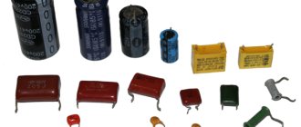
Electric capacitors are two-terminal devices designed to store charge and energy from an electric field. They are components of any pulse or electronic circuit. The part consists of two plates, between which there is a dielectric. The thickness of the latter is somewhat less than the plates themselves. Capacitance is measured in Farads.
Many types of capacitors do not have polarity. That is why, when connecting, the question arises - how to determine the polarity of an electrolytic capacitor.
By appearance
If the markings are worn out or unclear, determining the polarity of the capacitor is sometimes possible by analyzing the appearance of the case.
In many containers with terminals located on one side and not mounted, the positive leg is longer than the negative leg. Products of the ETO brand, now obsolete, look like 2 cylinders placed on top of each other: a larger diameter and small height, and a smaller diameter, but significantly higher. The contacts are located in the center of the ends of the cylinders. The positive terminal is mounted at the end of a cylinder with a larger diameter. For some powerful electrolytes, the cathode is located on the body, which is connected by soldering to the chassis of the electrical circuit. Accordingly, the positive terminal is isolated from the housing and located on its upper part.
The polarity of a wide class of foreign, and now domestic, electrolytic capacitors is determined by the light stripe associated with the negative pole of the device. If the polarity of the electrolyte cannot be determined either by the markings or by its appearance, then even then the problem of “how to find out the polarity of a capacitor” is solved by using a universal tester - a multimeter.
Checking without instruments
Without measuring parameters, a malfunction is indicated by appearance defects:
- stains on the surface of the body;
- swelling, deformation of the upper notch on imported electrolytic capacitors;
- electrolyte leakage.
Other methods of troubleshooting are used at home. You should:
- connect to a power source, the voltage should not exceed the rated voltage;
- take an LED (low-voltage lamp with two wires), touch the leads of the LED to the legs of the capacitor;
- LED flash (short-term glow of the lamp) will confirm serviceability.
To determine the performance of a large capacitor:
- connect to a power source whose voltage is less than the rated voltage;
- remove the charge with a metal object.
The presence of a spark during discharge will confirm suitability.
When removing a charge, be careful and take protective measures, as the discharge is accompanied by a powerful spark and sound. To reduce the spark, a discharge is used through a resistor
What happens if you reverse the polarity?
If you make a mistake with the polarity of an electrolytic capacitor, it will definitely fail! The resistance of the capacitor with reverse polarity is small, so a significant current will flow through its circuit. This will cause rapid overheating, boiling of the electrolyte, the vapors of which will rupture the housing. The same effect will be caused by an increase in operating voltage above that indicated on the case. To eliminate bad consequences, the top cover of the case is made profiled, with grooves-recesses on the top cover.
It will be interesting What is the difference between a starting capacitor and a working capacitor?
With increased pressure inside, the lid diverges along these grooves, releasing vapors out. It should be noted that electrolytic capacitors used in computer power supplies and motherboards may fail after several years of normal operating conditions. The fact is that in capacitors, due to the presence of electrolyte, electrochemical processes constantly occur, aggravated by heavy operating conditions and elevated temperatures.
What other parameters characterize capacitors?
Generally speaking, there are many such parameters. We are not having a Nobel lecture here, so we will limit ourselves to only the necessary minimum, which will be useful in practical activities. Rated operating voltage. The capacitor can be used in modes when the voltage across it does not exceed the operating voltage.
For example, you can use an electrolytic capacitor with an operating voltage of 10 V in +5 V or +3 V circuits.
The higher the operating voltage of an electrolytic capacitor with equal capacity, the larger its dimensions.
The operating voltage on ceramic and other capacitors may not be explicitly stated or not stated at all - especially if the capacitor is small.
Complete information about all parameters of the capacitor is available in the corresponding datasheet (reference data), which is available on the website of the manufacturer.
ESR (Equivalent Series Resistance) - equivalent series resistance. The capacitor terminals and their contacts with the plates have non-zero, although very small, resistance. This resistance is active, therefore, in accordance with Ohm's and Joule-Lenz's laws, when current flows through this resistance, heat will be dissipated.
This will cause the capacitor to heat up.
Therefore, electrolytic capacitors usually indicate the maximum operating temperature.
Computer power supplies and motherboards use special capacitors with reduced ESR.
The ESR value for such capacitors can range from hundredths to tenths of an Ohm.
The ESR value can be determined by special markings (most often 2 Latin letters) on the capacitor body. The correspondence of these letters to real ESR values is indicated in the datasheet.
Parallel connection
Several capacitors can be connected in series or in parallel. When connected in parallel, the capacitances of all capacitors are summed. With a series connection, the total capacitance of the capacitor bank is less than the smallest one, since the reciprocals of the capacitances are added. But the voltage at which such a battery can operate will be greater than the operating voltage of one capacitor.
Material on the topic: all about the variable capacitor.
On motherboards, the low-voltage voltage source circuit that powers the processor core uses several similar capacitors connected in parallel. An interesting question: why not put one capacitor with a capacity equivalent to the capacitance of a bank of capacitors? The fact is that for parallel-connected capacitors, the total ESR will be much less than the ESR of one capacitor. Because when resistances are connected in parallel, the total resistance decreases.
Capacitor connections.
LED polarity: how to determine plus and minus
When using LEDs in creating various circuits, they must be installed correctly. Soldering in most cases does not create problems; determining the polarity is a little more difficult if you do not have experience working with testing equipment.
How to determine polarity with a multimeter tester
The easiest way to check the LED is with a multimeter. When connecting the pins in the “dialing” mode to the electrodes, you can get 2 results: the LED lights up and displays a number on the screen depending on the color of the radiation, or shows a very large number. With the first option, we can conclude that the light source is working and connected to the multimeter correctly (plus to plus, minus to minus).
The second method of using a multimeter is to switch to resistance testing. If the red probe touches the plus, the black probe touches the minus, a value in the range of 1600–1800 appears on the screen.
If the multimeter has a PNP compartment, the E (emitter - “+”) and C (collector – “-”) compartments are required to determine the polarity of the LED. The light source glows if the cathode is inserted into “C” and the anode into “E”.
If an NPN multimeter compartment is used, the LED will light if the legs are swapped.
By appearance
In the production of LEDs, different housings are used. DIP elements with a cylindrical body of various diameters are widely used. There are many surface mount SMDs being manufactured. Ultra-bright light sources differ in the size of their housings and crystals. An experienced radio amateur determines the cathode and anode by external signs.
- longer anode leg;
- the silhouette in the flask is smaller at the anode, the shape of the cathode resembles a flag;
- a source with a power of more than 1 W has a “+” marking on the anode leg.
- the cathode is indicated by a cut on the body;
- the heat sink on the back of the case is located closer to the anode;
- The “P” pictogram is facing the anode with the top shelf, the top of the “T” pictogram is facing the cathode.
Some manufacturers put certain symbols on SMD LED housings that allow you to determine the polarity.
Important! There are SMDs made according to a different principle (some manufacturers do not comply with the standards). On complex models there are always symbols “+” and “−”
Any non-semiconductor radio tube (zener diode) consists of an anode, cathode and grid. The cathode is always a heated electrode made in the shape of a cylinder. During thermionic emission, electrons move to the anode (box or plate) - a tungsten conductor with high resistance.
To determine the performance of the zener diode, use a multimeter in ringing mode. If a positive probe is applied to the anode, a negative probe to the cathode, the zener diode will open and the voltage value will be visible on the screen. If you swap the probes, the zener diode will close and the number 1 will appear on the screen.
By supplying power
To use power connection testing, a 3-6V source and any wattage resistor of 300-470 ohms are required. The resistor is soldered to one leg of the multimeter. Then you need to touch the leads with the probes. The LED lights up if the positive probe touches the anode, and the negative probe touches the cathode.
Technical documentation
A large amount of information (dimensions, pinout, electrical parameters) about the semiconductor light source is provided by manufacturers in the technical documentation. It is issued when purchasing large quantities of electronic components along with other accompanying documentation. If you buy one or more LEDs, the seller will not provide technical documentation.
If the brand of the product is known, the data can be found in reference books and on the Internet.
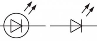
In the diagram, a semiconductor light source is indicated by a pictogram in the shape of a triangle, at the top of which a line is drawn perpendicular to the base. The top is directed towards the cathode. The LED is indicated by 2 arrows above the image.
How to determine where is the anode and where is the cathode?
When determining the cathode and anode, you must first focus on the direction of the current, and not on the polarity of the power source. Despite the fact that these concepts are closely related to the polarity of the current, they are more determined by the directions of the electricity vectors.
For example, in batteries, when recharging, the roles of the cathode and anode change. This is due to the fact that during charging the direction of the electric current changes. The electrode that acts as an electrode when the battery is operating in power source mode during charging performs the functions of a cathode and vice versa - the cathode turns into an anode.
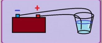
In Fig. 1, the electrolysis process is depicted, during which the movement of anions (negative ions) and cations (positive ions) occurs. Anions rush towards the anode, and positive cations move towards the cathode.
Rice. 1. Electrolysis
During electrolysis, charge carriers of different signs move, however, by definition, the anode is the electrode into which current flows. In the figure, the anode is connected to the positive pole of the current source, which means that current conditionally flows into this electrode.
Pay attention to Figure 2, which shows a diagram of a galvanic cell. Rice
2
Galvanic cell
2. Galvanic cell
Rice. 2. Galvanic cell
The positive terminal of the current source is the cathode, and not the anode, as one might expect. By carefully studying the operating principle of a galvanic cell, you can understand why the anode is the negative pole.
Pay attention to the diagram of the structure of a galvanic current source. The arrows (above) indicate the direction of movement of electrons, but the direction of current is conventionally considered to be movement from plus to minus
That is, when the circuit is closed, the current enters precisely the negative pole, which is the anode on which the oxidation reaction occurs
In other words, the current from the positive electrode passes through the load to the anode, which is the negative pole of the galvanic cell. With a thoughtful approach, everything falls into place
That is, when the circuit is closed, the current enters precisely the negative pole, which is the anode on which the oxidation reaction occurs. In other words, the current from the positive electrode passes through the load to the anode, which is the negative pole of the galvanic cell. With a thoughtful approach, everything falls into place.
When determining the positions of the anode and cathode in radio-electronic elements, reference materials are used.
The purpose of the electrodes is indicated by:
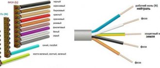
- body shape (Fig. 3);
- lead length (for LEDs) (Fig. 4);
- marks on the housings of devices or the anode mark;
- different thickness of diode leads.
Rice. 3. Diode
Rice. 4. LED electrodes Determining the pin assignments of semiconductor diodes can be determined using measuring instruments. For example, all types of diodes (except zener diodes) conduct current in only one direction. If you connect a tester or ohmmeter to a diode and it shows insignificant resistance, then the anode is connected to the positive probe of the device, and the cathode is connected to the negative probe.
If the conductivity type of the transistor is known, then using the same tester you can determine the emitter and collector terminals. Between them, the resistance is infinitely high (there is no current), and between the base and each of them there will be conductivity (only in one direction, like a diode). Knowing the type of conductivity, by analogy with a diode, you can determine where the anode is and where the cathode is, and therefore determine the terminals of the collector or emitter (see Fig. 5).
Rice. 5. Transistor on the circuits and its electrodes
As for vacuum diodes, they cannot be checked by measuring with conventional instruments. Therefore, their pins are located in such a way as to eliminate connection errors. In electronic tubes, the terminals exactly match the location of the contacts of the socket intended for this radio element.
General information
A capacitor is a passive element of an electrical circuit that is capable of storing charge and instantly releasing it in the event of a discharge. The design of the simplest capacitive element includes:
- linings (plates);
- dielectric layer located between the plates;
- frame;
- leads (electrodes).
Between the plates there is a gap filled with a dielectric; an air gap can be used as a dielectric. This is how elements of variable capacity are arranged.
Important! Including a polar capacitor in a capacitive two-terminal circuit requires connecting its negative terminal to the general negative of the circuit, and the positive terminal to the general positive of the assembly.
Electrolytic polar bipolar networks include:
- aluminum;
- polymer (niobium or tantalum).
Inclusion in a circuit with incorrect polarity leads to failure of the element and possible damage to neighboring components if it explodes. Polar capacitors stand out from the rest of the series due to their high capacitance.
The capacitance of a two-terminal network is designated by the letter C and has the unit of measurement farad (F). 1 farad is a large value even for electrolytic two-terminal networks. Therefore, the most commonly used submultiple units of capacity are:
- microfarad – 1 mF = 1*10-6 F;
- nanofarad – 1 nF = 1*10-9 F;
- picofarad – 1 pF = 1*10-12 F.
The electrolytic element of the container consists of two plates. The first is aluminum foil, the second is the electrolyte. The dielectric is an oxide layer deposited on the foil.
For polymer capacitors, the anode is a porous tantalum or niobium foil on which an oxide layer of dielectric is applied. The cathode is a semiconductor layer that is deposited directly onto the oxide layer.
Attention! The service life of the electrolytic two-terminal network reaches 5000 hours at the maximum permissible temperature. It follows that an increase in operating temperature leads to a reduction in performance.
The metal anode has a positive potential, and the electrolyte has a negative potential. Reversal of polarity when connecting leads to loss of dielectric capacity of the oxide coating and a short circuit between the plates. The electrolyte heats up and the resulting gases rupture the housing. To reduce the consequences of a rupture, notches are made in the upper part of the body.
How to test a non-polar capacitor with a multimeter
The operation of radio electronics also involves troubleshooting equipment. Therefore, when considering non-polar capacitors, one cannot abstract from the topic of diagnosing their performance.
As practice shows, in most cases the cause of tank failure is breakdown, which leads to a decrease in leakage resistance. That is, the element practically becomes a conductor. Such a malfunction can often be determined by the appearance of the container (see Figure 5); if this does not help, you will need a simple digital or analog multimeter.
Figure 5. “Burnt” (broken) container
Using the device, you should measure the leakage resistance; in the working elements it should be infinitely large. The check is performed as follows:
- it is necessary to completely dismantle the part, or unsolder one of its terminals, in order to exclude the influence of other circuit elements on the multimeter readings;
- set the device to continuity testing or resistance measurement mode (select the maximum limit);
- we connect the probes to the output contacts (Figure 6), while trying not to touch them, otherwise the device will show skin resistance;
Figure 6. Connecting the container to the measuring device
We carry out a measurement; if the capacitance is in good condition, one will be displayed on the screen (Figure 7), which indicates an infinitely large resistance between the plates.
Figure 7. The device in dialing mode shows an infinitely high resistance
Unfortunately, this method can only test the capacitance for breakdown; this method is not suitable for determining an internal break. In this case, you can distinguish a broken part from a functional one by measuring its capacity; some models of multimeters have this functionality. The principle of testing is practically the same as testing for breakdown, with the exception that the device must be switched to capacitance measurement mode.
Characteristic signs of electrolyte malfunction
These signs include:
- The device does not turn on. The power supply goes into protection or does not start;
- The device turns on but immediately turns off. The capacitance of the capacitors has dried out or lost its previous value, so the power supply goes into protection;
- Before the malfunction there was a squeaking sound in the power supply. This usually means that the capacitor has lost its seal and the electrolyte begins to leak;
- There is no brightness adjustment on the monitor. The lack of the required capacity leads to disruption of the entire device. The capacity in this case does the setting function;
- Before the malfunction there was an explosion and an unpleasant smell. The unpleasant odor is an electrolyte;
- The device turns on once. This means that there is a high probability of the power filter leaking.
External signs of malfunction of electrolytic capacitors:
- Bloating of the body;
- Hull damage:
- Presence of electrolyte under the housing;
- Swelling on the side of the contacts (at the bottom of the case, usually barely noticeable).
Also, high-frequency pulsations harm electrolytes. Therefore, most often they fail in power supplies, since that is where there is a lot of ripple.
Rules for working with electrolytes
Attention! Before touching the board of a faulty source, make sure that the capacitors are discharged. Even if the converter is faulty and not the electrolyte, the capacitors can be charged
They simply have nowhere to put their charge. Therefore, first of all, carefully and without touching the multimeter probe, measure the capacitances with high voltage. If they are charged, discharge them using a light bulb.
How to change old to new
There are two opinions among electronics engineers. The first thing is that you need to replace a faulty old capacitor with an equally old one. This is explained by the fact that the entire operation of the circuit has become “accustomed” to the old capacitor.
But the technically correct and well-founded opinion is that you need to install only a new capacitor that meets the parameters. There is no addictive pattern. Yes, many components are outdated and cannot work as before, but the capacitor essentially has nothing that would radically affect the deterioration of the performance of all circuits. On the contrary, the device will work better.
Replace old capacitors with new ones that are as close as possible in parameters. For example, you can take a little more capacity if we are talking about a power supply. And if this is a tuning circuit, then by increasing or decreasing the capacitance, you can influence the entire operating mode of the circuit. You need to act according to the situation.
Also, do not forget about such a parameter as ESR (equivalent series resistance).
Post Views: 637
Purpose of the diode
Semiconductor diode elements are present in almost all household electrical appliances. LEDs are used in the production of lighting fixtures and LED TVs.
Semiconductor diodes are classified according to:
- crystal material (silicon, selenium, indium phosphide, germanium);
- sizes (microalloy, spot, flat);
- pn junction production technologies (diffusion, alloy, epitaxial);
- frequency (low-frequency, high-frequency, ultra-high-frequency, impulsive);
- area of use (rectifiers and special ones).
Rectifier diodes are designed to convert alternating voltage to direct voltage. They are installed in the circuit in the form of a diode bridge, which can be used in radio equipment, power supply, charger.
Rectifiers are divided into:
- low current (up to 0.3 ampere);
- average power (0.3-10 amperes);
- power (10-100,000 A, up to 6 kV).
Semiconductor special diode elements:
- varicaps (capacitive diodes);
- thyristors (with an additional output for switching to the open state);
- triacs (current passes in 2 directions);
- Zener diodes (stabilize voltage from 2 volts in a breakdown state, a separate type of stabiistors (normistors) for a voltage of 0.7-2 volts);
- Schottky diodes (for low-voltage circuits paired with a zener diode);
- tunnel diode elements (low negative resistance);
- dinistors (do not contain control electrodes, are mounted in switches);
- magnetic diodes (volt-ampere characteristics change in a magnetic field, mounted in motion sensors, control devices);
- photodiodes (convert light energy into electrical energy);
- LEDs (convert electrical energy into light).
Capacitor positive symbol
On domestic Soviet products, only the positive contact was indicated with a “+” sign. This sign was applied to the case next to the positive terminal. Sometimes in the literature the positive terminal of electrolytic capacitors is called the anode, since they not only passively accumulate charge, but are also used to filter alternating current, i.e. have the properties of an active semiconductor device. In some cases, the “+” sign is also placed on the printed circuit board, close to the positive terminal of the drive located on it.
On products of the K50-16 series, polarity markings are applied to the bottom, made of plastic. For other models of the K50 series, for example K50-6, the “plus” sign is painted on the bottom of the aluminum case, next to the positive terminal. Sometimes imported products produced in the countries of the former socialist camp are also marked on the bottom. Modern domestic products meet global standards.
The marking of SMD (Surface Mounted Device) capacitors intended for surface mounting (SMT - Surface Mount Technology) differs from ordinary ones. Flat models have a black or brown body in the form of a small rectangular plate, part of which at the positive terminal is painted over with a silver stripe with a plus sign on it.
Video
Battery polarity
Coffee capsule Nescafe Dolce Gusto Cappuccino, 3 packs of 16 capsules
1305 ₽ More details
Coffee capsules Nescafe Dolce Gusto Cappuccino, 8 servings (16 capsules)
435 ₽ More details
Shockproof smartphones
Methods for determining capacitor polarity
By labeling
For most domestic electrolyte capacitors, as well as a number of states of the former socialist camp, only a positive conclusion is indicated. Accordingly, the second one is a minus. But the symbolism may be different. It depends on the country of manufacture and year of manufacture of the radio component. The latter is explained by the fact that regulatory documents change over time and new standards come into force.
Examples of capacitor plus designation
- There is a “+” symbol on the body near one of the legs. In some episodes it passes through its center. This applies to cylindrical capacitors (barrel-shaped), with a plastic “bottom”. For example, K50-16.
- For capacitors of the ETO type, the polarity is sometimes not indicated. But you can determine it visually by looking at the shape of the part. The “+” terminal is located on the side with a larger diameter (in the figure there is a plus at the top).
If the capacitor (the so-called coaxial design) is intended for installation by connecting the housing to the “chassis” of the device (which is a minus of any circuit), then the central contact is a plus, without any doubt.
Minus symbol
This applies to imported capacitors. Next to the “–” leg, on the body there is a kind of barcode, which is a broken strip or a vertical row of dashes. Alternatively, a long strip along the center line of the cylinder, one end of which points to the minus. It stands out from the general background with its shade.
By geometry
If the capacitor has one leg longer than the other, then this is a plus. Basically, imported products are also labeled in a similar way.
Using a multimeter
This method of determining the polarity of a capacitor is practiced if its markings are difficult to read or completely erased. To check, you need to assemble a circuit. You will need either a multimeter with an internal resistance of about 100 kOhm (mode – I= measurement, limit – microamps)
or DC source + millivoltmeter + load
What to do
- Completely discharge the capacitor. To do this, it is enough to short-circuit its legs (with the tip of a screwdriver or tweezers).
- Connect the container to the open circuit.
- After the charging process is completed, record the current value (it will gradually decrease).
- Discharge.
- Include it in the diagram again.
- Read the instrument readings.
Recommendation. It is advisable to determine the polarity with the device in any case. This will allow you to simultaneously diagnose the part. If an electrolyte with a large nominal value is charged relatively quickly from a source of 9±3 V, then this is evidence that it has “dried up”. That is, it has lost part of its capacity. It is better not to put it in the circuit, since its operation may be incorrect, and you will have to make additional settings.
Marking of tantalum elements
To simplify the development of structures, transportation, and automation of work operations, products in this category are produced using certain standard sizes: A; IN; C; D; E; V. The largest dimensions are 7.3 x 4.3 x 4.1 mm. It is clear that the size of such areas is not enough to accommodate long inscriptions. This explains the need to use special abbreviations.
Marking for tantalum SMD capacitors
The general rules for designating these parts correspond to the standard procedure for forming identification inscriptions on the housings of miniature resistors. The main difference is the use of the typical capacitance designation in microfarads - “µ”.
Example for "686":
- 68 – main number;
- 6 – degree of multiplier (106);
- a simple mathematical operation calculates the capacitance rating: 68 * 106 = 68 μF.
Voltage is indicated by adding the letter “v” after the corresponding number. Standard coding is also used (designation - voltage, volts):
The thick line marks the polarity (plus, anode).
Additional codes indicate:
- execution option;
- release date;
- manufacturer.
Polar and non-polar capacitors - what is the difference
All kinds of capacitors, used today almost everywhere in electronics and electrical engineering, contain various substances as dielectrics
However, with regard specifically to electrolytic capacitors, in particular also tantalum and polymer ones, when they are included in the circuit, it is important to strictly observe polarity. If such a capacitor is connected incorrectly to the circuit, it will not be able to work normally.
These capacitors are therefore called polar capacitors. What is the fundamental difference between a polar capacitor and a non-polar one? Why is it that some capacitors do not care how they are included in the circuit, while for others it is fundamentally important to maintain polarity?
It will be interesting Formula for calculating capacitor resistance
Let's try to figure this out now. The point here is that the manufacturing process for electrolytic capacitors is very different from, say, ceramic or polypropylene. If for the latter two both the plates and the dielectric are homogeneous in relation to each other, that is, there is no difference in the structure at the plate-dielectric interface on both sides of the dielectric, then electrolytic capacitors (cylindrical aluminum, tantalum, polymer) have a difference in the structure of the dielectric transition -plating on both sides of the dielectric: the anode and cathode differ in chemical composition and physical properties.
When an electrolytic aluminum capacitor is made, they do not simply roll up two identical foil plates lined with electrolyte-impregnated paper. On the side of the anode plate (to which + is applied) there is a layer of aluminum oxide applied to the etched surface of the foil in a special way. The anode is designed to give electrons through an external circuit to the cathode during the charging of the capacitor. The negative plate (cathode) is simply aluminum foil; during the charging process, electrons come to it through an external circuit. The electrolyte here serves as a conductor of ions.
Polar and non-polar capacitors.
The same is the case with tantalum capacitors, where tantalum powder serves as the anode, on which a film of tantalum pentoxide is formed (the anode is connected to the oxide!), which functions as a dielectric, then there is a layer of semiconductor - manganese dioxide as an electrolyte, then a silver cathode, from which electrons will leave during the discharge process.
Polymer electrolytic capacitors use a lightweight conductive polymer as the cathode, but otherwise the processes are similar. The essence is oxidation and reduction reactions, like in a battery. The anode is oxidized during the electrochemical discharge reaction, and the cathode is reduced.
When an electrolytic capacitor is charged, there is an excess of electrons at its cathode, on the negative plate, imparting a negative charge to this terminal, and at the anode, a lack of electrons, giving a positive charge, thus obtaining a potential difference. If a charged electrolytic capacitor is connected to an external circuit, then excess electrons will run from the negatively charged cathode to the positively charged anode, and the charge will be neutralized. In the electrolyte, positive ions move at this moment from the cathode to the anode.
If such a polar capacitor is connected incorrectly to the circuit, then the described reactions will not be able to proceed normally, and the capacitor will not work normally. Non-polar capacitors can operate in any connection, since they have neither an anode, nor a cathode, nor an electrolyte, and their plates interact with the dielectric in the same way as with the source.
Capacitor polarity.
But what if you only have polar electrolytic capacitors at hand, but you need to connect the capacitor to a current circuit with changing polarity? There is one trick for this. You need to take two identical polar electrolytic capacitors and connect them together in series with terminals of the same name. You will get one non-polar capacitor from two polar ones, the capacitance of which will be 2 times less than each of its two components.
It will be interesting What is a variable capacitor
On this basis, by the way, non-polar electrolytic capacitors are made, in which an oxide layer is present on both plates. For this reason, non-polar electrolytic capacitors are significantly larger than polar capacitors of similar capacity. Based on this principle, electrolytic starting non-polar capacitors are also manufactured, designed to operate in alternating current circuits with a frequency of 50-60 Hz.
Polar and non-polar capacitor
General concept
What is capacitor polarity and how to determine it?
A capacitor consists of two conductive plates and a dielectric between them. And that's it, nothing more. It looks like a simple radio component, but it works differently at high and low frequencies.
Indicated on the diagram by two parallel lines.
Principle of operation
This radio component demonstrates well the phenomenon of electrostatic induction. Let's look at it with an example.
If you connect a constant current source to the capacitor, then at the initial moment of time the current will begin to accumulate on the plates of the capacitor. This occurs due to electrostatic induction. Resistance is practically zero.
The electric field, due to electrostatic induction, attracts opposite charges to two opposite plates. This property of matter is called capacity. All materials have a capacity. And even for dielectrics, but for conductors it is much greater. Therefore, the capacitor plates are made of conductor.
The main property of a capacitor is capacitance.
As charges accumulate, the field begins to weaken and the resistance increases. Why is this happening? There is less and less space on the plates, like charges on them act on each other, and the voltage on the capacitor becomes equal to the current source. This resistance is called reactive or capacitive. It depends on the frequency of the current, the capacitance of radio components and wires.
When there is no room left on the plates for electric current, then the current in the circuit will stop. Electrostatic induction disappears. Now there remains an electric field that holds the charges on its plates and does not let them go. And the electric current has nowhere to go. The voltage across the capacitor will become equal to the emf (voltage) of the current source.
What happens if you increase the EMF (voltage) of the current source? The electric field will begin to put more and more pressure on the dielectric, since there is no more space on the plates. BUT if the voltage on the capacitor exceeds the permissible knowledge, then the dielectric will break through. And the capacitor will become a conductor, the charges will be released, and the current will flow through the circuit. How then to use a capacitor for high voltages? You can increase the size of the dielectric and the distance between the plates, but this reduces the capacitance of the part.
Between the plates there is a dielectric that prevents the passage of direct current. This is precisely the barrier to direct current. Because constant current also creates constant voltage. And a constant voltage can create electrostatic induction only when the circuit is closed, that is, when the capacitor is charging.
This way the capacitor can store energy until a consumer connects to it.
Capacitor and DC circuit
Let's add a light bulb to the diagram. It will only light up while charging. Another important feature is that when the current charging process occurs, the voltage lags behind the current. The voltage seems to catch up with the current, since the resistance increases smoothly as it charges. Electrical charges take time to move to the capacitor plates. This is the charging time. It depends on capacitance, frequency and voltage.
The light goes out when fully charged.
Direct electric current does not pass through the capacitor until it is charged.
AC circuit
What if you change the polarity on the current source? Then the capacitor will begin to discharge and charge again as the polarity of the source changes.
Electrostatic induction occurs constantly if the electric current is alternating. Every time the current begins to change its direction, the process of charging and discharging begins.
Therefore, the capacitor passes alternating electric current.
The higher the frequency, the lower the reactance (capacitive) resistance of the capacitor.