Home > Theory > Designation of capacitors in the diagram
Capacitors are available in different designs and for different applications. At the same time, there are excellent conventional graphic symbols of capacitor elements on electrical circuits. In addition, markings are used on the parts themselves.
Various types of capacitor elements
About the capacitor
The basic structure of a capacitor has a simple explanation. Between the two capacitor plates there is a dielectric that insulates the two conducting surfaces. Thus, a capacitor is a passive device capable of storing electrical charge.
The capacitor films, dielectric and design largely determine the properties of the capacitor, namely the ability to store a charge that is proportional to the voltage applied to its plates. This proportionality, called capacitance, is considered an essential feature of the capacitor.
Technologically, capacitors can be divided into three types:
- electrostatic;
- electrolytic;
- other electrochemical devices (double-layer).
The use of a capacitor depends on the type and purpose of the circuit. A buffer capacitor element is used to intercept peak loads. These elements are used in filters to suppress interference and build resonant circuits.
Compound
Parallel connection
To obtain large capacities, capacitors are connected in parallel. In this case, the voltage between the plates of all capacitors is the same. The total capacity of a battery of parallel-connected capacitors is equal to the sum of the capacitances of all capacitors included in the battery.
Serial connection
With a series connection, the total capacitance is always less than the minimum capacitance of one of the capacitors included in the battery. However, with a series connection, the possibility of breakdown of capacitors is reduced, since each capacitor accounts for only part of the potential difference of the voltage source.
Constant capacitor
Divided into two main types:
- polarized;
- non-polar.
Small-sized non-polarized capacitor elements can be connected in any direction. There are different types, but ceramic is the most widely used and suitable for most purposes.
On electrical circuits they are indicated by a pair of short parallel lines perpendicular to the connecting circuit lines. The capacitance value of the element is often placed nearby.
Designation of a capacitor with a constant capacitance
Important! Sometimes in foreign schemes the designation MFD is found. These are not megafarads, but μF.
Possible capacity units:
- micro (μ) means 10 to the -6 power of farad;
- nano (n) – 10 to the -9 degree farad;
- pico (p) – 10 to the -12 degree farad.
The capacitance value is also applied to the surface of the capacitor itself. It is often indicated without unit symbols, especially on small elements. For example, 0.1 is 1 µF = 100 nF.
Sometimes writing units is used instead of a decimal point. If the designation 4n7 appears, this means 4.7 nF.
Capacitor number code
Digital code is often used on small items where printing is difficult:
- the first two numbers are the initial digits of the capacity value;
- the third shows the number of zeros, and the value itself is measured in pF;
- letters may indicate tolerances and voltage ratings.
For example:
- 102 means 1000 pF, not 102 pF;
- 472J is 4700 pF (J indicates 5 percent tolerance).
Important! Non-polar capacitors usually have a capacitance of less than 1 µF.
Alphanumeric designation
If you disassemble old Soviet equipment, then everything will be quite simple - on the cases it says “22pF”, which means 22 picofarads, or “1000 uF”, which means 1000 microfarads. Old Soviet capacitors were usually large enough to allow such “long texts” to be written on them.
Global, so to speak, alphanumeric marking involves the use of letters of the Latin alphabet:
- p – picofarads,
- n – nanofarads
- m – microfarads.
At the same time, it is useful to remember that if we conventionally take picofarad as a unit of capacity (although this is not entirely correct), then the letter “p” will denote units, the letter “n” – thousands, the letter “m” – millions. In this case, the letter will be used as a decimal point. Here is a clear example, a capacitor with a capacity of 2200 pF, according to this system will be designated 2n2, which literally means “2.2 nanofarads”. Or a capacitor with a capacity of 0.47 µF will be designated m47, that is, “0.47 microfarads”.
It will be interesting➡ How much do ceramic capacitors cost?
Moreover, domestically produced capacitors have similar markings in Cyrillic, that is, picofarads are designated by the letter “P”, nanofarads by the letter “N”, microfarads by the letter “M”. But the principle is the same: 2H2 is 2.2 nanofarads, M47 is 0.47 microfarads. For some types of miniature capacitors, “μF” is designated by the letter R, which is also used as a decimal point, for example:
1R5 =1.5 µF.
Polarized capacitors
Capacitor Capacitance Meter
Capacitor elements of this type must be connected according to the poles. This is shown in the diagram by the “+” symbol. On the device itself it is indicated by markings that identify the “plus”. For cylindrical parts, a longer lead is usually a plus. Polarized capacitors are not damaged during soldering.
Polarized capacitors
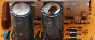
Electrolytic capacitors are the most widely used type of polarized capacitor element. They are available in two versions:
- cylindrical, with both terminals at one end;
- axial, with leads at each end.
Cylindrical ones tend to be a little smaller and cheaper.
The actual dimensions of such elements are large enough to clearly indicate on them the value of capacitance, rated voltage and indicate the “positive” terminal. Therefore they are easy to identify.
Important! When turned on in the opposite direction, the elements can be damaged and even explode, so polarity must be strictly adhered to.
The voltage rating of electrolytic capacitors is quite low. In the absence of clear requirements, it is better to choose a part with a rating slightly higher than the circuit voltage.
The electrolytic capacitor element in the diagrams can be indicated in three versions, shown in the figure.
Designation of polarized capacitors
Tantalum capacitors
Tantalum capacitors are polarized and have low breakdown voltage. They have very small dimensions and are used in special situations where size is important.
On the latest models of tantalum capacitor elements, the value of capacitance, voltage and “positive” terminal are indicated. Older models have a color code system that conventionally indicates capacity.
The code consists of two stripes at the top of the element (for two digits) and a color spot indicating the number of zeros. The correspondence of color values for specific containers is determined from the tables. A gray spot means that the capacitive value in uF should be multiplied by 0.01, white - by 0.1. The lower band near the capacitor terminals gives the voltage value:
- yellow – 6.3 V;
- black – 10 V;
- green – 16 V;
- blue – 20 V;
- gray – 25 V;
- white – 30 V;
- pink – 35 V.
Important! The “positive” contact is always on the right side of the element, if you place it with the color spot facing you.
Tantalum capacitors
Main parameters and characteristics
Capacity.
An important parameter of a capacitor is its nominal capacity. For a flat capacitor the formula is valid:
С = (ε*ε 0 *S) / d,
where ε is the dielectric constant of the dielectric, S is the dimensions of the plates (plate area), d is the distance between the plates (plates).
The actual capacity of individual elements is usually small, but you can get a structure with a capacity of several farads if you connect a huge number of plates in parallel. In this case, the real capacity is equal to the sum of all the capacitances of the plates.
The maximum capacitance of some capacitors can reach several farads.
Specific capacity.
A value characterizing the ratio of capacity to volume or mass of a radio component. This parameter is important in microelectronics, where the dimensions of the parts are very important.
Rated voltage.
One of the important electrical characteristics is the rated voltage - the value of the maximum voltages at which the capacitor can operate without losing the values of its other parameters. When a critical value equal to the breakdown voltage is exceeded, the dielectric is destroyed. Therefore, the rated voltage is chosen to be obviously greater than any possible maximum amplitudes of the sinusoidal current in the capacitor circuit.
There are characteristics, such as loss tangent, temperature coefficient of capacitance, leakage resistance, dielectric absorption, etc., that are of interest only to specialists, and their parameters can be found in special reference books.
Variable capacitors
Three-phase motors in a single-phase network: connection diagrams and selection of capacitors
This type of capacitor element is mainly used in radio circuits. The element consists of two disk systems. One is fixed permanently, the other can rotate, entering the gaps between the stationary disks. Variable parts have small capacitances, 100-500 pF, and are not used in electrical synchronization circuits due to the small capacitive value and limited limits of available values. Instead, conventional capacitors with fixed capacitance values and variable resistors are used.
Designation of variable capacitors
In the diagram, variable capacitors are represented by a capacitor symbol crossed out by an inclined arrow, and instead of the exact capacitance value, the limits of its change are written.
Capacitor trimmers
A type of variable capacitor elements are trimmers, these are miniature parts with variable capacitance. They are mounted directly on the printed circuit board, and the capacitive value changes only during the setup period of the circuit. That's why they are also called tuning ones. Adjustment is made using a screwdriver.
Designation of trimmer capacitor
The capacitive value of the trimmer is usually less than 100 pF. On the electrical diagram, the trimmer is indicated as a variable capacitor with an arrow, only the arrow has a perpendicular line instead of a point. The range of capacitance change is written next to it.
Code marking, addition
According to IEC standards, in practice there are four ways to encode the nominal capacity.
A. 3-digit marking
The first two digits indicate the capacitance value in pygofarads (pf), the last one indicates the number of zeros. When the capacitor has a capacitance of less than 10 pF, the last digit may be "9". For capacitances less than 1.0 pF, the first digit is “0”. The letter R is used as a decimal point. For example, code 010 is 1.0 pF, code 0R5 is 0.5 pF.
| Code | Capacitance [pF] | Capacitance [nF] | Capacitance [µF] |
| 109 | 1,0 | 0,001 | 0,000001 |
| 159 | 1,5 | 0,0015 | 0,000001 |
| 229 | 2,2 | 0,0022 | 0,000001 |
| 339 | 3,3 | 0,0033 | 0,000001 |
| 479 | 4,7 | 0,0047 | 0,000001 |
| 689 | 6,8 | 0,0068 | 0,000001 |
| 100* | 10 | 0,01 | 0,00001 |
| 150 | 15 | 0,015 | 0,000015 |
| 220 | 22 | 0,022 | 0,000022 |
| 330 | 33 | 0,033 | 0,000033 |
| 470 | 47 | 0,047 | 0,000047 |
| 680 | 68 | 0,068 | 0,000068 |
| 101 | 100 | 0,1 | 0,0001 |
| 151 | 150 | 0,15 | 0,00015 |
| 221 | 220 | 0,22 | 0,00022 |
| 331 | 330 | 0,33 | 0,00033 |
| 471 | 470 | 0,47 | 0,00047 |
| 681 | 680 | 0,68 | 0,00068 |
| 102 | 1000 | 1,0 | 0,001 |
| 152 | 1500 | 1,5 | 0,0015 |
| 222 | 2200 | 2,2 | 0,0022 |
| 332 | 3300 | 3,3 | 0,0033 |
| 472 | 4700 | 4,7 | 0,0047 |
| 682 | 6800 | 6,8 | 0,0068 |
| 103 | 10000 | 10 | 0,01 |
| 153 | 15000 | 15 | 0,015 |
| 223 | 22000 | 22 | 0,022 |
| 333 | 33000 | 33 | 0,033 |
| 473 | 47000 | 47 | 0,047 |
| 683 | 68000 | 68 | 0,068 |
| 104 | 100000 | 100 | 0,1 |
| 154 | 150000 | 150 | 0,15 |
| 224 | 220000 | 220 | 0,22 |
| 334 | 330000 | 330 | 0,33 |
| 474 | 470000 | 470 | 0,47 |
| 684 | 680000 | 680 | 0,68 |
| 105 | 1000000 | 1000 | 1,0 |
* Sometimes the last zero is not indicated.
B. 4-digit marking
4-digit coding options are possible. But even in this case, the last digit indicates the number of zeros, and the first three indicate the capacity in picofarads.
| Code | Capacitance[pF] | Capacitance[nF] | Capacitance[uF] |
| 1622 | 16200 | 16,2 | 0,0162 |
| 4753 | 475000 | 475 | 0,475 |
C. Capacitance marking in microfarads
The letter R may be used instead of the decimal point.
| Code | Capacitance [µF] |
| R1 | 0,1 |
| R47 | 0,47 |
| 1 | 1,0 |
| 4R7 | 4,7 |
| 10 | 10 |
| 100 | 100 |
D. Mixed alphanumeric marking of capacity, tolerance, TKE, operating voltage
Unlike the first three parameters, which are marked in accordance with standards, the operating voltage of different companies has different alphanumeric markings.
| Code | Capacity |
| p10 | 0.1 pF |
| IP5 | 1.5 pF |
| 332p | 332 pF |
| 1NO or 1nO | 1.0 nF |
| 15H or 15n | 15 nF |
| 33H2 or 33n2 | 33.2 nF |
| 590H or 590n | 590 nF |
| m15 | 0.15uF |
| 1m5 | 1.5 µF |
| 33m2 | 33.2 µF |
| 330m | 330 µF |
| 1mO | 1 mF or 1000 μF |
| 10m | 10 mF |
Code marking of electrolytic capacitors for surface mounting
The following coding principles are used by such well-known companies as Hitachi and others. There are three main coding methods:
A. Marking with 2 or 3 characters
The code contains two or three characters (letters or numbers) indicating the operating voltage and rated capacity. Moreover, the letters indicate voltage and capacitance, and the number indicates the multiplier. In the case of a two-digit designation, the operating voltage code is not indicated.
| Code | Capacitance [µF] | Voltage [V] |
| A6 | 1,0 | 16/35 |
| A7 | 10 | 4 |
| AA7 | 10 | 10 |
| AE7 | 15 | 10 |
| AJ6 | 2,2 | 10 |
| AJ7 | 22 | 10 |
| AN6 | 3,3 | 10 |
| AN7 | 33 | 10 |
| AS6 | 4,7 | 10 |
| AW6 | 6,8 | 10 |
| CA7 | 10 | 16 |
| CE6 | 1,5 | 16 |
| CE7 | 15 | 16 |
| CJ6 | 2,2 | 16 |
| CN6 | 3,3 | 16 |
| CS6 | 4,7 | 16 |
| CW6 | 6,8 | 16 |
| DA6 | 1,0 | 20 |
| DA7 | 10 | 20 |
| DE6 | 1,5 | 20 |
| DJ6 | 2,2 | 20 |
| DN6 | 3,3 | 20 |
| DS6 | 4,7 | 20 |
| DW6 | 6,8 | 20 |
| E6 | 1,5 | 10/25 |
| EA6 | 1,0 | 25 |
| EE6 | 1,5 | 25 |
| EJ6 | 2,2 | 25 |
| EN6 | 3,3 | 25 |
| ES6 | 4,7 | 25 |
| EW5 | 0,68 | 25 |
| GA7 | 10 | 4 |
| GE7 | 15 | 4 |
| GJ7 | 22 | 4 |
| GN7 | 33 | 4 |
| GS6 | 4,7 | 4 |
| GS7 | 47 | 4 |
| GW6 | 6,8 | 4 |
| GW7 | 68 | 4 |
| J6 | 2,2 | 6,3/7/20 |
| JA7 | 10 | 6,3/7 |
| JE7 | 15 | 6,3/7 |
| JJ7 | 22 | 6,3/7 |
| JN6 | 3,3 | 6,3/7 |
| JN7 | 33 | 6,3/7 |
| JS6 | 4,7 | 6,3/7 |
| JS7 | 47 | 6,3/7 |
| JW6 | 6,8 | 6,3/7 |
| N5 | 0,33 | 35 |
| N6 | 3,3 | 4/16 |
| S5 | 0,47 | 25/35 |
| VA6 | 1,0 | 35 |
| VE6 | 1,5 | 35 |
| VJ6 | 2,2 | 35 |
| VN6 | 3,3 | 35 |
| VS5 | 0,47 | 35 |
| VW5 | 0,68 | 35 |
| W5 | 0,68 | 20/35 |
Ionistor
The ionistor is called a supercapacitor. It is a two-layer element with a relatively high capacity (0.22-10 F). The structure of a supercapacitor is different from that of a conventional electrolytic part. In the double layer, a zone of stationary charge carriers is formed at the interface between the electrode surface and the electrolyte, where energy is stored as an electrostatic field, in contrast to the chemical energy of the electrolytic capacitor element. Since the boundary layer is extremely thin and the electrode surface is large, high capacitance is achieved, making the supercapacitor suitable for use as a power supply.
Ionistor and its designation
