Over the last two decades, small-sized digital multimeters with an LCD display and self-powered devices have been popular among radio amateurs. Multimeters of the lowest price category, for example, from the M83x, RT83x series, are cheap, but inconvenient to use, have low measurement accuracy, and do not contain elements of protection against improper use.
More serious multimeters with automatic range selection, protection, and increased measurement accuracy are already several times more expensive.
Even if you don’t burn out the multimeter, for example, by connecting it to a 220 V AC voltage network when its work type switch is in the resistance measurement position, sooner or later, or rather sooner, with intensive use of the device, the printed contacts of the switch will become unusable from wear. Measuring instruments with automatic selection of measurement limits allow you to extend the service life of the work type switch.
The service life of multimeters will be further extended if several multimeters are used simultaneously at the workplace, each of which most of the time measures only one electrical quantity, which will reduce the need to use the type of work switch. For example, the author has one multimeter that measures resistance, another that measures capacitance, a third that measures alternating current, a fourth that tests semiconductor junctions, etc.
But it so happened that there was no dedicated multimeter for measuring DC voltage. In order not to once again switch one of the involved multimeters to measure voltages, it was decided to make a simple pointer voltmeter, which, having only one function for measuring DC voltage, would partially relieve the used multimeters from “extra” switching types of work.
It was decided to assemble a voltmeter similar to the circuit from [1], adapting it to the available parts and specific needs. It should be noted that about a quarter of a century ago, the author had already manufactured a multimeter based on the circuit from that publication, which is usually used as an AC voltage millivoltmeter and as a phase meter [2].
The analogue representation of the measured voltage is usually more visual in case of rapid changes - no over-under interpretation is required, but provides less accuracy than a digital indication. It was decided to make the voltmeter with an input resistance of more than 20 MΩ; for comparison, cheap digital multimeters usually have an input resistance in voltage measurement mode of only 1 MΩ or 10 MΩ, and the magnetoelectric TL-4M is only about 300 kΩ in the “30 V” DC range.
The number of ranges for the voltmeter was chosen to be four, according to the number of positions of the available compact slide switch. The voltmeter is powered from an alternating current network, which eliminates the periodic need to replace batteries.
ERRORS AND ACCURACY CLASSES OF ELECTRICAL INSTRUMENTS
ERRORS AND ACCURACY CLASSES OF ELECTRICAL MEASURING INSTRUMENTS
The value measured by a device always differs from the true value by a certain number, called the instrument error. The errors of measuring instruments are determined by verification, i.e., by comparing the readings of the device being verified with the readings of a more accurate, standard device when they measure the same value. The value of the measured quantity, determined using a reference device, is considered to be valid. However, the actual value differs from the true one by the error inherent in this reference device. There are absolute, relative and reduced measurement errors.
Absolute error
a measuring instrument is the difference between its reading and the actual value of the measured quantity.
Relative error
called the ratio of the absolute error to the actual value of the measured value, expressed in relative units or as a percentage.
Reduced error
is the ratio of the greatest absolute error to the upper measurement limit of the device.
Based on the value of the given error, measuring instruments are divided into groups according to accuracy class. Accuracy class
is
a generalized characteristic of a measuring device that determines the limits of permissible errors. For electrical measuring instruments, the accuracy class is indicated in the form of a number equal to the maximum permissible reduced error (in %). According to GOST 1845-59, electrical measuring instruments are divided into 8 accuracy classes: 0.05; 0.1; 0.2 – exemplary devices; 0.5; 1.0 – laboratory; 1.5; 2.5; 4.0 – technical devices. Model instruments are considered to be of a higher accuracy class in relation to laboratory and technical instruments, and laboratory instruments are considered to be of a higher accuracy class in relation to technical ones.
Let us determine its errors based on the accuracy class of the device. If a device (for example, a voltmeter with an upper measurement limit of 150 V) has an accuracy class of 1.0, then the main reduced error does not exceed 1 %
.
The maximum absolute error that the device can have at any point on the scale will not exceed. The relative error depends on the measured voltage.
If this voltmeter can measure a voltage of 10 V, then the relative error can be
. If you measure a voltage of 100 V, then the relative error can be
From this example it is clear that in order to increase the measurement accuracy, the device must be selected so that, firstly, it has a higher accuracy class, and so that, secondly, the measurement limit is close to the value of the measured value. This means that in order to obtain the smallest possible relative errors, it is necessary to achieve a sufficiently large deflection of the arrow (it is desirable that the last third of the scale be used).
On the other hand, in order to achieve greater accuracy when measuring with a device of a lower class, it is necessary to select a device with the smallest possible measurement range.
The proposal should be correctly formulated, which provides a quantitative estimate of the error. For example: “Current measurement with an absolute error of up to 1 mA”, “Current measurement with a relative error of up to 1 %.
(The expression “Current measurement accurate to 1 mA” is incorrect).
Source
Multi-limit instrument
Anyone who has repeatedly encountered transistor designs and circuits knows that very often with a voltmeter it is necessary to measure circuits with voltages from tens of fractions of one volt to hundreds of volts. A simple homemade device with one resistor will not do this, so you will have to connect several elements with different resistances to the circuit. So that you understand what we are talking about, we suggest that you familiarize yourself with the diagram located below:
It shows that there are four resistors installed in the circuit, each of which is responsible for its own measurement range:
- From 0 volts to one.
- From 0 volts to 10V.
- From 0 V to 100 volts.
- From 0 to 1000 V.
The value of each resistor can be calculated based on Ohm's law. The following formula is used here:
- Rп is the resistance of the measuring unit, take, for example. 500 Ohm;
- Up is the maximum voltage of the measured limit;
- Ii is the current strength at which the needle deflects to the end of the scale, in our case - 0.0005 amperes.
For a simple voltmeter from a Chinese ammeter, you can choose the following resistors:
- for the first limit – 1.5 kOhm;
- for the second – 19.5 kOhm;
- for the third – 199.5;
- for the fourth – 1999.5.
But the relative resistance value of this device will be equal to 2 kOhm/V. Of course, the calculated values do not coincide with the standard ones, so resistors will have to be selected close in value. Next, the final adjustment is carried out, during which the device itself is calibrated.
What do you need to know about the accuracy class of a measuring device?
Measuring instruments: voltmeters, ammeters, current clamps, oscilloscopes and others are devices designed to determine the required values in a given range, each of them has its own accuracy, and devices measuring the same value, depending on the model, may differ in terms of accuracy and class.
In some situations, it is enough to simply determine the value, for example , the voltage of a battery, while in others it is necessary to perform multiple repetitions of measurements with high-precision instruments to obtain the most reliable result, so what is the difference between such measuring devices, what does the accuracy class mean, how many of them are there, how is it determine and much more, read further in our article.
Retro technology, homemade products and the fight against idiocy
I don’t yet know what kind of modding project this measuring head will be used in, so I decided to write a separate post about it. I am posting the information hot on the heels, literally and figuratively: successful technology was found only yesterday.
So, in my household I had an old M24 series dial gauge, calibrated as a millivoltmeter/milliammeter. From a functional point of view it was serviceable, but the scale had clearly seen better days, so it was no longer suitable for my purposes.
Previously, when people asked me why I didn’t change instrument scales in my mods, marked in some extraneous quantities, I answered that I didn’t want to spoil the original old things. And this was true, but only half: the fact is that even if I wanted to change some scale to a new one, I would not know how to do it efficiently.
I made my first attempt to adapt this device for use in conjunction with a computer several years ago, when, based on a scan of the original scale, I drew my own and printed it on old paper.
The scale, frankly speaking, came out very poorly. It looked ugly, the yellow color of the paper did not match the other details, and the division price in the lower part of it turned out to be fractional.
Therefore, I did not use this device anywhere and put it in a drawer for a long time. But recently I took it out of there and decided to do everything right this time. First of all, I connected it to a voltage source and accurately calibrated it, putting pencil marks from 0 to 100 (it was decided to mark one of the scales as a percentage in order to use it to display a wide variety of values).
I then removed the timeline and scanned it.
I wanted the new scale to look nice and authentic. So I dug through a drawer of old pointer heads and found one that I liked best.
Using various Photoshop tools, I removed as much of the original background as possible and superimposed the resulting image on top of the scan with pencil marks. By a happy coincidence, it turned out that it was enough to just scale the new scale a little so that it perfectly matches the drawn one. Apparently, the devices have the same type of mechanisms with a nonlinear dependence of the angle of deviation on the voltage - if you look closely at the scale, you will notice that the interval from 0 to 1 is noticeably larger than the interval from 9 to 10.
The following picture shows an intermediate stage of work: some of the numbers are still missing, some areas have not been redrawn, and uncollected “garbage” is visible.
In order for the device to end up looking as close to the real thing as possible, I did not use characters from new fonts, but only copied the original ones. If I had to use the same number twice, I deliberately deformed it a little so that there would not be a perfect digital copy. This kind of pedantry may not be very healthy :-). The debris had to be removed manually, because I do not know of an automatic cleaning mechanism that would remove the dust without blurring the contours.
In the end it turned out like this:
The first scale displays percentages, the second - temperature (calibrated according to the temperature sensor datasheet, which does not guarantee the accuracy of readings below zero), and the third - processor frequency in megahertz. I left the nostalgic value “IMP / MIN” because, as they say, it is on topic. Due to the gradual compaction of the divisions, the marks on the temperature scale turned out to be very small, but it was decided to ignore this. At the very end I added an outline of the metal backing to make the scale easy to cut out and place in place.
It was possible to remove the inscriptions from the original scale using ordinary soap. If soap does not help, you can try alcohol, acetone, solvent 646, acetic acid or hydrogen peroxide - in my practice there has never been a case when this “cocktail” did not work.
But this was all just a prelude, the real witchcraft is yet to come. I didn’t even consider printing the new scale on paper, but instead began to think about how to apply the inscriptions directly onto the original aluminum plate. The easiest thing, of course, would be to load it into an inkjet printer converted for printing on hard surfaces (some cool radio amateurs make these for making printed circuit boards), but this option had to be discarded due to the lack of a suitable printer. I also remembered such a thing as metal printing, but it also requires special equipment, and I wanted to find a method that I could use at home.
Therefore, it was decided to master another technology from the arsenal of radio amateurs - LUT (“laser-ironing”). It has been described so many times on the Internet that I see no point in repeating it. In short, a design is printed using a laser printer on some smooth paper in a mirror image, after which it is transferred to the desired surface using heat. This method is used to create tracks on printed circuit boards, but in my case the last technological stage - etching - was not needed.
I haven’t used LUT before, so I decided to practice on cats first. After reading many recommendations, I chose two intermediate media - semi-gloss magazine pages and photo paper of unknown origin.
What is accuracy class
Definition: “Measurement accuracy class is a general characteristic of the accuracy of a measuring instrument, determined by the limits of permissible main and additional errors, as well as other factors influencing it.”
The class itself is not a constant measurement value, because the measurement itself often depends on many variables: the measurement location, temperature, humidity and other factors; the class allows you to determine only in what range of relative errors a given device operates.
Normative reference values can also be used to estimate in advance the error that the device will measure.
Relative error is the ratio of the absolute error to the module of the actual approximate indicator of the obtained value, measured in %.
The absolute error is calculated as follows:
∆=±a or ∆=(a+bx)
x – number of divisions, normalizing the value of the quantity
a, b – positive numbers independent of x
Absolute and reduced errors are calculated using the following formulas, see table below
What accuracy classes are there and how are they designated?
As we have already found out, the error interval is determined by the accuracy class. This value is calculated and established by GOST and technical conditions. Depending on the specified error, it can be: absolute, reduced, relative, see table below
According to GOST 8.401-80 in the SI system, accuracy classes are usually marked with a Latin letter, often with the addition of an index marked with a number. The smaller the error, respectively, the smaller the number and the higher the letter value in the alphabet, the higher the accuracy.
The accuracy class is indicated on the device body as a number circled, indicating the range of measurement errors as a percentage. For example, the number ② indicates a relative error of ±2% . If there is a check mark next to the symbol, this means that the scale length is used as an auxiliary determination of the error.
- 0,1, 0,2 – considered the highest class
- 0,5, 1 – more often used for devices in the mid-price category, for example, household ones
- 1,5, 2,5 – used for measuring instruments with low accuracy or indicators, analog sensors
TRANSISTOR DC VOLTMETER
The transistor DC voltmeter is designed as an attachment to an avometer (more precisely, to an avometer microampere meter) and has six DC voltage measurement limits: 0.5; 1; 5; 10; 50 and 100 V. With proper adjustment of its amplifier and careful selection of additional resistors, the instrument error does not exceed ±5%, which is quite sufficient for amateur measurements. The relative input resistance of the voltmeter is 100 kOhm/V.
The schematic diagram of the voltmeter is shown in Fig. 30. It uses a balanced DC amplifier made on transistors VT1 and VT2. The measured voltage is supplied to the bases of both transistors through one of the additional resistors R1-R6. The measuring device PA1 (microammeter avometer) is connected between the collectors of the transistors.
In order for the scales of different measurement limits of a voltmeter to be linear, the transistors must operate in the linear portion of the current-voltage characteristic. To do this, a small initial negative bias voltage is applied to the bases of the transistors through resistors R8-R10. Balancing the amplifier before measurements (setting the microammeter needle to the zero scale mark) is carried out by variable resistors R9 and R16 First
Rice. 30. Schematic diagram of a transistor DC voltmeter
of them serves to equalize the base currents of transistors, the second - collector currents. .
The use of a balanced amplifier in the device reduces the “drift of the loop” and the more, the smaller the difference in the current values 1KB0 of the transistors used in it.
The transition from one measurement limit to another is carried out by switching additional resistors R1-R6. The resistances of these resistors are selected so as to obtain the full deflection of the microammeter needle when voltages corresponding to the measurement limits are applied to the input. Using a separate resistor for each limit simplifies voltmeter calibration.
The sensitivity of the balanced amplifier at the input is 5... 7 µA when using a microammeter with a current of 1u = 100 µA. In order for resistors of standard values to be used as additional resistors, the sensitivity of the b-line amplifier is artificially reduced to 10 μA using variable resistor R7.
The device is powered by a stabilized voltage of 9 V, taken from the unregulated output of the mains power supply. Since a supply voltage of 3...3.5 V is quite sufficient for the voltmeter to operate, another stabilization stage has been introduced on the silicon zener diode VD1. Two-stage stabilization of the supply voltage reduces the measurement error during significant fluctuations in the power supply voltage.
To power the voltmeter, you can also use a built-in battery of galvanic cells or batteries with a voltage of 3... 3.5 V, slightly increasing the dimensions of the set-top box for this. It should be noted that in this case, as the battery discharges, the measurement error will increase.
Rice. 31. External view of the voltmeter and its connection to the avometer and power supply
Construction and details. The general view of the voltmeter attachment along with the avometer and writing block is shown in Fig. 31. The load-bearing structural element of the console is housing 1 (Fig. 32), made of sheet aluminum alloy AMts-P 1 mm thick. Cover 2 is also bent from the same material. It is connected to the body with M2 screws with countersunk heads. With the same screws, plate 3 is attached to the lid, performing the functions of instrument legs and providing the required distance between the plugs connecting the attachment to the avometer and the table plane. The plate can be made from any insulating material with a thickness of 3J5...4 mm.
Plug block 5 can be made of getinax or textolite with a thickness of 2.,. 3 mm, and the plugs themselves 4 are made from pieces of brass rod with a diameter of 3 and a length of 30 .. 32 mm with a thread ^MZ at the end. The plugs are screwed into the threaded holes in the block and finally secured with nuts 6. Mounting tabs 7 are first placed under the nuts. The block is secured to the body with M2X6 screws with countersunk heads.
The installation of parts in the console body is shown (on both sides) in Fig. 33. On the front panel (in Fig> 33 it faces down) there is a variable resistor R9 (“Set 0”), a power switch Q1, a block with sockets XS1—XS? and a two-wire cord ending with plugs for connecting to the power supply. On the side wall of the case there is a plug block for connecting the attachment to the microammeter of the avometer.
As in the avometer, inscriptions explaining the purpose of the device, its sockets and controls are printed on strips of paper of two colors glued end-to-end and protected from damage by a 2 mm thick plexiglass cover.
To fasten the cover to the body of the console, the nuts of the toggle switch of the power switch Q1 and the variable resistor R9 are used.
The structure of the block with sockets XS1—XS7 is shown in Fig. 34. Contacts 4 are secured to the block with 6 screws. The block 6 itself is secured to the body of the console with screws 8 (MZHb with a countersunk head), screwed into its threaded holes on the outside of the body 7. ζ the same holes, but on the other side, screws 1 (MZH12) are screwed in, securing the mounting plate 3. For To create the necessary gap between the board and the block, tubular stands 2 with a height of 6 mm are put on screws 1.
The layout of circuit board 3 and the wiring diagram of the voltmeter are shown in Fig. 35. The board is made of getinax sheet 2 mm thick, mounting
Fig 33 View of the installation of a transistor voltmeter
Fig. 34. Construction of the socket block and its fastening in the voltmeter body
Figure 35. Marking the voltmeter circuit board and placing parts on the board
racks are made of tinned copper wire with a diameter of 1.5 mm. All connections on the board are made of tinned copper wire with a diameter of 0.5 mm. At intersections, pieces of polyvinyl chloride tube are placed on it. To connect the mounting board >with parts fixed to the body, a flexible mounting wire MGShV with a cross-section of 0.14 mm2 is used.
The following parts are used in the voltmeter: variable resistors SP-F (R9), SPO-0.5 (R16), SPZ-16 (R7); fixed resistors MLT-0.5, toggle switch *TP1-2 (Ql); transistors with static current transfer coefficient ==*50 (40...60).
The KS133A zener diode can be replaced with four planar silicon diodes (for example, D226 series), connecting them in series in the forward direction.
It is very important that the transistors have the same characteristics of forward current transmission (dependence of the collector current on the base current) and the reverse collector current IKB0 of no more than 2 ... 3 μA. To select a pair of transistors, it is convenient to use the measuring circuit shown in Fig. 36. Here VT is the transistor being tested, RA is the avometer microammeter, variable resistor R2 is used to set the base current, resistor R1 limits it when the resistor R2 slider is installed in the uppermost (according to the circuit) position, resistor R3 is a shunt that increases the measurement limit current microammeter RA yes 10 mA. In the position of the switch SA1, shown in the diagram, the base current of the transistor VT is measured using the device RA (set by a variable resistor R2), in the position “I*” - the corresponding collector current. Battery GB - 3336L or any three galvanic cells (332, 343, 373). AfterFig. 36. Diagram for selecting transistors for a voltmeter
carefully setting the base currents from 10 to 80... 100 µA (every 5... -.. 10 µA), fix the corresponding collector currents and select specimens with the closest characteristics from the number of available transistors. Reverse collector currents are measured at temperatures of 15 and 40 ° C. Transistors are suitable for a voltmeter in which this parameter at the indicated temperatures is approximately the same (the permissible* difference is no more than 10 ... 20%).
It is advisable to first assemble and adjust the voltmeter on a breadboard mounting panel and only after that transfer the parts to the circuit board of the device.
Setting up a voltmeter begins with setting the stabilization current of the zener diode VD1." To do this, the wire connecting the resistor R14 to the motor of the variable resistor R16 (Fig. 35) is temporarily unsoldered, and the circuit consisting of resistor R13 and the zener diode is connected through a milliammeter designed for current
50.. . 100 mA, connect to the rectifier. By selecting resistor R13, the current through the zener diode is set within 25 ... 30 mA, after which the connection between resistors R14 and R16 is restored.
Next, the sliders of resistors R9 and R16 are set to the middle position, turning on the power of the voltmeter, and resistor R9 is used to set the microammeter needle to the zero scale mark. Then the terminals of the bases of the transistors are temporarily connected with a wire jumper and using the tuning resistor R16, the absence of current through the microammeter is ensured. After this, the conductor connecting the terminals of the transistor bases is removed and resistor R9 is used to again set the arrow to the zero mark of the scale. These operations are repeated several times until the microammeter needle stops responding either to the connection of the bases or to their separation.
If the voltmeter amplifier uses transistors with a static current transfer coefficient h2i3 = 45... 50, then the setup of the device ends. If the coefficient b21e of the transistors is less than this value, for example, does not go beyond 30... 40, the resistance of the resistors R8 and R10 must be reduced to 22... 27 kOhm.
Calibration of a transistor DC voltmeter is practically no different from the calibration of an avometer in the DC voltage measurement mode described in the previous section (see p. 33). To calibrate the voltmeter to
In the first four limits (0.5; L; 5 and 10 V), you can use a power supply with an adjustable output voltage. Having set the voltage to 1 V using a standard voltmeter, connect the connecting wires to the “—General” sockets. and “1 V” of the device being calibrated and, moving the resistor adjustment slider R7, set the microammeter needle to the last mark of the constant voltage scale.
When calibrating the remaining measurement limits, resistor R7 is not touched, but additional resistors R1 and $3-R6 corresponding to the included limit are selected.
To calibrate the limits of 50 and 100 V, a DC source with a voltage of 100 ... 110 V is required. This can be the rectifier of any tube receiver.
Having completed the calibration, the parts are transferred from the breadboard panel to the circuit board of the voltmeter. Lastly, variable resistors R7 and R16 are soldered. In a fully assembled device, the amplifier balancing and calibration are checked at one of the measurement limits. If during installation the sliders of trimming resistors R7 and R16 accidentally move, then the sensitivity of the amplifier is balanced and adjusted again, after which the sliders of these resistors are fixed with drops of nitro paint.
Using the described voltmeter, they check from time to time and, if necessary, adjust the balancing of the amplifier with resistor R9, setting the microammeter needle to the zero scale mark.
Source: Borisov V. G., Frolov V. V., Measuring laboratory of a beginning radio amateur. - 3rd ed., stereotype. - M.: Radio and Communications, 1995. - 144 pp., ill. - (Mass Radio Library; Issue 1213).
Tweet Like
- Previous post: HIGHLY DIRECTIONAL IN-PHASE ANTENNAS
- Next entry: FM Mini transmitter with two transistors
- POWER SUPPLY FOR CAR RADIO (0)
- BATTERY ELECTRICAL ISOLATION DEVICE (0)
- BATTERY CHARGING CURRENT LIMITER (0)
- MULTIPLE LITHIUM CELL CHARGER (0)
- BATTERY VOLTAGE LEVEL INDICATOR (0)
- BATTERY STATUS INDICATOR (0)
- CONNECTION DIAGRAM OF A LITHIUM BATTERY FOR POWERING MEMORY DEVICES (0)
Related posts:
How to determine the accuracy class of an electrical measuring instrument, calculation formulas
To determine the accuracy class, you need to look at its case or user manual, in it you can see a number circled, for example , ① this means that your device measures a value with a relative error of ±1%.
But what to do if the relative error is known and it is necessary to calculate the accuracy class of, for example, an ammeter, voltmeter, etc. Let's look at the example of an ammeter: known ∆x=basic (absolute) error 0.025 (see instructions), number of divisions x=12
We find the relative error:
( conclusion: accuracy class – 2.5).
It should be noted that the error is uneven over the entire scale range; by measuring a small value you can get the greatest inaccuracy and as the desired value increases, it decreases; for example, consider the following option:
Voltmeter with class p=±2, upper limit of device readings Xn=80V, number of divisions x=12
Absolute permissible error limit:
Relative error of one division:
If you need to perform a more detailed calculation,
see GOST 8.401-80 clause 3.2.6.
Verification results. How is it confirmed?
According to the current rules, our laboratory specialists enter data on the verification of the voltmeter into the register of the Federal State Information System "Arshin". Previously mandatory certificates are no longer legally binding. You may receive a written opinion, but it will be for informational purposes only.
The period for checking a voltmeter is on average 7-10 working days. You can find out more by calling or leaving a request on our website. Managers will answer all questions in detail and agree on a date convenient for you. On the agreed day, you can personally bring the voltmeter or order courier delivery.
We always do our best to accommodate our clients, therefore, if necessary, we are ready to carry out urgent verification – both periodic and extraordinary. Our laboratories use high-quality precision testing equipment and have experienced staff. We guarantee reliable voltmeter verification results and affordable rates!
How to calculate the accuracy class of a device
ERRORS AND ACCURACY CLASSES
OF ELECTRICAL MEASURING INSTRUMENTS
The value measured by a device always differs from the true value by a certain number, called the instrument error. The errors of measuring instruments are determined by verification, i.e., by comparing the readings of the device being verified with the readings of a more accurate, standard device when they measure the same value. The value of the measured quantity, determined using a reference device, is considered to be valid. However, the actual value differs from the true one by the error inherent in this reference device. There are absolute, relative and reduced measurement errors.
Absolute error
a measuring instrument is the difference between its reading and the actual value of the measured quantity.
Relative error
called the ratio of the absolute error to the actual value of the measured value, expressed in relative units or as a percentage.
Reduced error
is the ratio of the greatest absolute error to the upper measurement limit of the device.
Based on the value of the given error, measuring instruments are divided into groups according to accuracy class. Accuracy class
is
a generalized characteristic of a measuring device that determines the limits of permissible errors. For electrical measuring instruments, the accuracy class is indicated in the form of a number equal to the maximum permissible reduced error (in %). According to GOST 1845-59, electrical measuring instruments are divided into 8 accuracy classes: 0.05; 0.1; 0.2 – exemplary devices; 0.5; 1.0 – laboratory; 1.5; 2.5; 4.0 – technical devices. Model instruments are considered to be of a higher accuracy class in relation to laboratory and technical instruments, and laboratory instruments are considered to be of a higher accuracy class in relation to technical ones.
Let us determine its errors based on the accuracy class of the device. If a device (for example, a voltmeter with an upper measurement limit of 150 V) has an accuracy class of 1.0, then the main reduced error does not exceed 1 %
.
The maximum absolute error that the device can have at any point on the scale will not exceed. The relative error depends on the measured voltage.
If this voltmeter can measure a voltage of 10 V, then the relative error can be
. If you measure a voltage of 100 V, then the relative error can be
From this example it is clear that in order to increase the measurement accuracy, the device must be selected so that, firstly, it has a higher accuracy class, and so that, secondly, the measurement limit is close to the value of the measured value. This means that in order to obtain the smallest possible relative errors, it is necessary to achieve a sufficiently large deflection of the arrow (it is desirable that the last third of the scale be used).
On the other hand, in order to achieve greater accuracy when measuring with a device of a lower class, it is necessary to select a device with the smallest possible measurement range.
The proposal should be correctly formulated, which provides a quantitative estimate of the error. For example: “Current measurement with an absolute error of up to 1 mA”, “Current measurement with a relative error of up to 1 %.
(The expression “Current measurement accurate to 1 mA” is incorrect).
The essence of a voltmeter
In some cases, using a conventional voltmeter with a linear scale may not be very convenient. For example, to monitor the charge-discharge voltage of a car or other similar battery, a voltmeter with a scale not from zero but, say, from a value of 10 volts is more convenient. Since such batteries are usually not discharged to lower values, and if they are discharged, this only indicates their improper use, probable inoperability and significant loss of capacity.
Thus, a voltmeter with an extended scale makes it possible to monitor values in the operating voltage range (for example, 10 ... 15 volts ). And even minor deviations in values are clearly visible and displayed more clearly.
As a dial indicator (measuring head), you can use any suitable size, for example, from an old tester (voltmeter, ammeter, ohmmeter, etc.) or even small dial indicators of the recording/playback level from audio electronic equipment. In this case, you only need to calculate the parameters of the nominal values of the parts used in the circuit and calibrate the indicator scale to the new values. We tell you how to do this below.
Instrument accuracy classes
According to the given error (by accuracy class), devices are divided into eight classes: 0.05; 0.1; 0.2; 0.5; 1.0; 1.5; 2.5; 4.0.
Devices of accuracy class 0.05; 0.1; 0.2; 0.5 are used for precise laboratory measurements and are called precision
(from the English precision - accuracy). In technology, devices of classes 1.0 are used; 1.5: 2.5 and 4.0 (technical).
The accuracy class of the device is indicated on the device scale. If there is no such designation on the scale, then this device is out of class, that is, its reduced error exceeds 4%. The manufacturer producing the device guarantees a relative measurement error with this device equal to the accuracy class (reduced error) of the device when measuring a value that throws the pointer off completely. scale. Having determined the accuracy class and limit value on the instrument scale, it is easy to calculate its absolute error ΔX = ± rXpr / 100%, which is assumed to be the same over the entire instrument scale. The signs “+” and “–” mean that an error can be made either in the direction of increase or decrease from the actual value of the measured value.
When using instruments for specific measurements, it rarely happens that the measured value causes the instrument needle to drop across its entire scale. As a rule, the measured quantity is smaller. This increases the relative measurement error. For optimal use of instruments, they are selected so that the values of the measured quantity fall at the end of the instrument scale; this will reduce the relative measurement error and bring it closer to the accuracy class of the instrument. In cases where the accuracy class is not indicated on the device, the absolute error is taken equal to half the value of the smallest division.
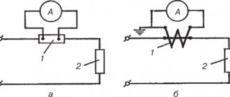
How to properly connect a voltmeter
Anyone who does not know, but wants to check the voltage on some part of the electrical network, must ask the question - how to connect a voltmeter? This is actually a serious question, the answer to which lies in a simple requirement - the voltmeter must be connected only in parallel with the load. If a serial connection is made, the device itself will simply fail and you may receive an electric shock.
Read also: Gray cast iron carbon content
The thing is that with such a connection the current strength acting on the measuring device itself decreases. At this resistance, it does not change, that is, it remains large. By the way, never confuse a voltmeter with an ammeter. The latter is connected to the circuit in series to reduce the resistance to a minimum.
And the last question on the topic is how to use a voltmeter that you made yourself. So, your device has two probes. One is connected to the neutral circuit, the second to the phase. You can also check the voltage through the socket, having previously determined which socket is powered by zero and which by phase. Or connect the device in parallel to the area being measured. The arrow of the measuring block will show the voltage value in the network. This is how they use this homemade measuring device.
We consider simple circuits of digital voltmeter and ammeter, built without the use of microcontrollers on the CA3162, KR514ID2 microcircuits. Typically, a good laboratory power supply has built-in instruments - a voltmeter and an ammeter. A voltmeter allows you to accurately set the output voltage, and an ammeter will show the current through the load.
Old laboratory power supplies had dial indicators, but now they should be digital. Nowadays, radio amateurs most often make such devices based on a microcontroller or ADC chips like KR572PV2, KR572PV5.
Instrument accuracy class 24651
The accuracy class determines the guaranteed limits beyond which the instrument’s error does not extend within the measurement range established for it.
KT accuracy class
electromechanical pointer measuring instruments are normalized in the form of a percentage ratio of the limit
Xmax
(guaranteed limits) of the absolute error of the device to the normalizing value
Xnorm
of its scale:
(2)
where the normalizing value Xnorm
for devices with a uniform scale, the upper limit of the value measured by the device is used, and for devices with an uneven scale, the length of its working part, i.e. the length of the section between the scale marks corresponding to the measurement range of the device.
For electromechanical pointer measuring instruments, the following accuracy class figures are established: 0.05; 0.1; 0.2; 0.5 (for laboratory instruments) and 1;.1.5; 2.5; 4 (for technical devices).
The accuracy class number of the device is indicated on its scale. For devices with a uniform scale, this figure is indicated without any signs (circles, squares, asterisks), for example, 2.5. For devices with an uneven scale, the accuracy class figure is emphasized by a broken line, for example, 2.5.
Determination of the accuracy class of the device
The accuracy class of a measuring instrument is a generalized characteristic determined by the limits of permissible basic and additional errors, as well as other properties affecting accuracy, the values of which are established in the standards for certain types of measuring instruments. The accuracy class of measuring instruments characterizes their properties in terms of accuracy, but is not a direct indicator of the accuracy of measurements performed using these instruments.
In order to estimate in advance the error that a given measuring instrument will introduce into the result, normalized error values are used. They mean the maximum errors for a given type of measuring instrument.
The errors of individual measuring instruments of this type may be different, have systematic and random components that differ from each other, but in general the error of a given measuring device should not exceed the standardized value. The limits of the main error and influence coefficients are entered in the passport of each measuring device.
The main methods for normalizing permissible errors and designating accuracy classes of measuring instruments are established by GOST.
On the scale of the measuring device, the value of the accuracy class of the measuring device is marked in the form of a number indicating the normalized value of the error. Expressed as a percentage, it can have values of 6; 4; 2.5; 1.5; 1.0; 0.5; 0.2; 0.1; 0.05; 0.02; 0.01; 0.005; 0.002; 0.001, etc.
According to their intended purpose, all voltmeters are divided
• Alternating current;
• Direct current;
• Selective;
• Phase sensitive;
• Pulse.
AC and DC voltmeters are used for measurements in networks with the appropriate type of current, but selective ones can separate the harmonic component of a complex signal and determine the root mean square value of the voltage.
Pulse voltmeters are commonly used to measure the amplitude of continuous pulse signals, and they are also capable of accurately determining the amplitude of a single pulse.
Phase-sensitive devices can measure changes in the components of complex voltages, making it possible to accurately study the amplitude-phase characteristics of amplifiers and other similar circuits.
Based on the operating principle, a distinction is made between electronic (digital or analogue) and electromechanical voltmeters (electromagnetic, thermoelectric, as well as magnetoelectric, electrodynamic and electrostatic).
All electromechanical devices, with the exception of thermoelectric ones, are essentially a conventional measuring mechanism with an indicating device. In all of them, additional resistances are used to expand the measurement limits.
Devices of this category, despite the rather high internal resistance, have a relatively large error, which makes it impossible to use them in experiments and research where increased data accuracy is required.
A thermoelectric voltmeter makes measurements using the electromotive force of one or more thermocouples, which heat up due to the incoming signal current. They are more accurate and compact compared to electromechanical voltage meters.
Electronic voltmeters, in turn, are divided into digital and analog.
A digital voltmeter converts a constant voltage value into a digital signal, which is displayed on the device display. This is done using an analog-to-digital converter.
In analog voltmeters, in addition to the magnetoelectric meter and additional resistors, there must be a measuring amplifier, which makes it possible to increase the internal resistance of the device several times and, accordingly, improve the accuracy of the readings.
How to determine the accuracy class of a pressure gauge
A pressure gauge is a measuring device that allows you to determine the value of excess pressure acting in a pipeline or in the working parts of various types of equipment.
Such devices are widely used in heating systems, water supply, gas supply, and other utility networks for municipal and industrial purposes. Depending on the operating conditions of the meter, there are certain restrictions on the permissible limit of its error. Therefore, it is important to know how to determine the accuracy class of a pressure gauge.
What is the accuracy class of a pressure gauge and how to determine it
The accuracy class of a pressure gauge is one of the main values characterizing the device. This is a percentage expression of the maximum permissible error of the meter, reduced to its measurement range.
The absolute error is a value that characterizes the deviation of the readings of the measuring device from the actual pressure value. The main permissible error is also distinguished, which is a percentage expression of the absolute permissible value of deviation from the nominal value. The accuracy class is associated with this value.
There are two types of pressure meters - working and standard.
Workers are used for practical measurement of pressure in pipelines and equipment. Exemplary meters are special meters that serve to verify the readings of working instruments and allow one to assess the degree of their deviation. Accordingly, standard pressure gauges have a minimum accuracy class.
The accuracy classes of modern pressure gauges are regulated in accordance with GOST 2405-88. They can take the following values:
Thus, this indicator has a direct relationship with the error. The lower it is, the lower the maximum deviation that the pressure meter can give, and vice versa. Accordingly, this parameter determines how accurate the meter readings are. A high value indicates less accurate measurements, while a low value indicates increased accuracy. The lower the accuracy class value, the higher the price of the device.
Finding out this parameter is quite simple. It is indicated on the scale as a numerical value, preceded by the letters KL or CL. The value is indicated below the last scale division.
The value indicated on the device is nominal. To determine the actual accuracy class, you need to perform verification and calculate it. To do this, several pressure measurements are carried out using a standard and working pressure gauge. After this, it is necessary to compare the readings of both meters to identify the maximum actual deviation. Then all that remains is to calculate the percentage of deviation from the measuring range of the device.
How to draw a scale on a dial indicator
Hello dear readers.
In this article I want to talk about how to draw the scale we need for our measuring instruments. I will draw a scale, which in scientific terms means calibrate, for my milliohmmeter, which I wrote about earlier. You can read the article here. And so we have a head, found who knows where and when, it had been lying around for a long time. We carefully disassemble it, but before we unscrew the scale, we immediately measure the radius of the arc where the divisions are located.
See Photo 1. We measure carefully, without damaging the rotating system of the measuring head, and remember its value. If you, like me, also have a paper one on the main scale plate, then you need to carefully remove it in hot water. This is what happened, look at photo 2. Photo 3 shows a freshly drawn new scale.
So, open the FrontDesigner_3.0 program, if you don’t have it, download it and install it.
After opening the program, a window similar to this will appear in front of you (screen 1).
Right-click on active field 1 and select “properties”. We set the size of the sheet on which we will draw the scale in accordance with its dimensions. Here you can choose the color of the sheet, I chose white.
Next, click on button 2 - “Scale” and screen 2 will open in front of us, the window can be expanded to full screen.
When I hover the cursor over the active field, the latter takes the form of a magnifying glass with the name “Magnifier”; if at this time you click on the left or right mouse, the image will run away and you will have to draw it all over again. So, take note of this. Perhaps this is a glitch only in my program, but I’m already used to it. Click on button 1 and select “Circular linear scale” from the drop-down list.
Then click “parameters” (see screenshot 3) and begin filling out the required fields. 1 – select the angle by which the arrow deflects, since for all measuring heads it is approximately 90°, then we set this value.
Next, we set the radius value that we measured and remembered. “Line” - set “yes”, in this case the arc on which the divisions are located will be visible in the figure. “Center of circle” - you can also put “yes” for convenience. “1.Divisions.Segments” - The number of large divisions, I have ten of them. “Divisions. Length mm” - since my scale is large, I set it to 7mm. “Divisions” - set “Yes” - we allow ourselves to draw divisions between large divisions. Next, as with large ones, we set the number of small divisions between two large ones - 10, set the height of the small divisions - 5mm. We don’t need “rotation” - set it to “0”. “Inscriptions” - set “Yes” - these are numbers above the divisions. “High. t - mm " - height of numbers. “Gap” - I set it to 3mm - this is the distance between large divisions and inscriptions. “Text angle” - 0. Further, see the screenshot. As a result, we get the scale that you see, but without the inscriptions. Click on button 2 – “Inscriptions” and look at screen 4.
Everything is clear here; opposite the number of each large segment we enter what we need. Next, click on the green checkmark - “Add scale to layout”, the main program window opens again, but with our scale - screen 5.
My milliohmmeter has two measurement limits, so I would like to display it on this scale. To do this, click on the “Scale” icon again and draw another scale for another limit (see screenshot 6).
The peculiarity of this scale is that the divisions are located on the other side of the arc. This is achieved by placing a minus sign in front of the numerical value of the division height. And I put "no" for small divisions. Next, click on the green checkmark and combine the two scales in the main window. To facilitate further work, turn on the scale grid by clicking on the corresponding button - 1. After that, in accordance with the dimensions of our scale - photo 2, draw a rectangle. We will then cut off the part we need along the sides of this rectangle. Now we can insert the text or icon we need, you’ll figure it out for yourself. We get screen 7.
Next, click on the printer icon and print the scale. I print mostly on matte photo printer paper. Now about gluing. First, cut out the scale blank along the lines of the rectangle. Then we degrease the aluminum scale (photo 2). Apply PVA glue to both pieces. Let it dry a little, carefully combine both pieces and iron them through fluoroplastic film with an iron at a temperature of 60 degrees Celsius. Then, using a file (I usually use a round, small file all the time), we cut off the unnecessary paper. We use an awl to pierce the holes for attaching the scale, and assemble the device in the reverse order. ALL. Look at photo 4. Hurray! Clear victory.
Yes, a little more. If it is assumed that the device will work not only at home, but also on the street, then the paper scale must be protected with a layer of colorless varnish. For these purposes, I always use colorless imported car varnish in aerosol packaging - “Body Acrylic”. Good luck to everyone, goodbye. K.V.Yu.
Source: www.kondratev-v.ru
Determination of error
Owners of measuring instruments are interested, first of all, in the maximum error characteristic of a pressure gauge. It depends not only on the accuracy class, but also on the measurement range. Thus, to obtain the error value, you need to make some calculations. For example, for a pressure gauge with a measurement range of 6 MPa and an accuracy class of 1.5, the error will be calculated using the formula 6*1.5/100=0.09 MPa.
It should be noted that only the main error can be calculated in this way.
Its value is determined by ideal operating conditions. It is influenced only by the design characteristics, as well as the assembly features of the device, for example, the accuracy of the graduation of divisions on the scale, the friction force in the measuring mechanism. However, this value may differ from the actual value, since there is also an additional error determined by the conditions in which the pressure gauge is operated. It can be affected by vibration of the pipeline or equipment, temperature, humidity level and other parameters.
Also, the accuracy of pressure measurement depends on another characteristic of the pressure gauge - the magnitude of its variation, which is determined during verification. This is the maximum difference in meter readings identified from the results of several measurements.
The magnitude of the variation largely depends on the design of the pressure gauge, namely on the method of balancing, which can be liquid (pressure from a liquid column) or mechanical (spring). Mechanical pressure gauges have a more pronounced variation, which is often due to additional friction due to poor lubrication or wear of parts, loss of spring elasticity and other factors.
Source