Holes are formed with the participation of ions of the semiconductor substance - atoms with escaped electrons. In reality, ionized atoms do not leave their place in the crystal lattice. In fact, there is a gradual change in the state of the atoms of a substance when electrons jump from one atom to another. A process arises that outwardly looks like the ordered movement of certain conventional positively charged particles - holes .
In an ordinary, pure semiconductor, the ratio of holes and free electrodes is 50%:50%. But as soon as a small amount of a substance—an impurity—is added to the semiconductor, this ratio undergoes significant changes. Depending on the characteristics of the added substance, the semiconductor acquires either pronounced electronic conductivity (n-type), or holes (p-type) become its main carriers.
A semiconductor junction (pn) is formed at the junction of two fragments of semiconductor material having different conductivities. It is an extremely thin region, depleted of carriers of both types. A pn junction has little resistance when the current direction is forward, and a very high resistance when the current direction is reverse.
A conventional semiconductor diode consists of a single semiconductor junction equipped with two terminals - an anode (positive electrode) and a cathode (negative electrode). Accordingly, the diode has the property of one-way conductivity - it conducts current well in the forward direction and poorly in the reverse direction.
What does this mean in practice? Let's imagine an electrical circuit consisting of a battery and an incandescent light bulb connected in series through a semiconductor diode. The light bulb will light only if the anode (positive electrode) is connected to the plus of the power source (battery) and the cathode (negative electrode) to the minus - through the filament of the light bulb.
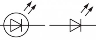
This is the direct connection of a semiconductor diode. If you reverse the polarity of the power source, the diode will turn on in reverse - the light bulb will not light. Pay attention to how the designation of a semiconductor diode looks on the diagram - a triangular arrow indicating direct connection coincides with the direction of current generally accepted in electrical engineering - from the plus of the power source to the minus. The vertical line adjacent to it symbolizes a barrier to the flow of current in the opposite direction.
There is one prerequisite for the normal operation of any semiconductor diode. The power supply voltage must exceed a certain threshold (the value of the internal bias potential of the pn junction). For rectifier diodes it is usually less than 1 volt, for germanium high-frequency diodes it is about 0.1 volt, for LEDs it can exceed 3 volts. This property of semiconductor diodes can be used to create low-voltage stabilized power supplies.
If you connect the diode back and gradually increase the voltage of the power supply, at some point a reverse electrical breakdown of the pn junction will definitely occur. The diode will begin to pass current in the opposite direction, and the junction will be damaged. The value of the maximum permissible reverse voltage (Urev.i.) varies widely among different types of semiconductor diodes and is a very important parameter.
The second, no less important parameter can be called the limiting value of the forward current - Upr. This parameter directly depends on the magnitude of the voltage drop across the junction of the semiconductor diode, the semiconductor material and the heat transfer characteristics of the housing.
What does a diode consist of?
In our world there are substances that perfectly conduct electric current. This mainly includes metals, for example, silver, copper, aluminum, gold and so on. Such substances are called conductors. There are substances that conduct electricity very poorly - porcelain, plastics, glass, and so on. They are called dielectrics or insulators. Between conductors and dielectrics are semiconductors. These are mainly germanium and silicon.
Once germanium or silicon is mixed with a minute fraction of arsenic or indium, an N-type semiconductor is formed when mixed with arsenic; or a P-type semiconductor when mixed with indium.
Now if these two P and N type semiconductors are welded together, a PN junction is formed at their junction. This is the structure of a diode. That is, the diode consists of a PN junction.
diode structure
The P-type semiconductor in the diode is the anode, and the N-type semiconductor is the cathode.
Let's open the Soviet D226 diode and see what's inside it by grinding off part of the body on an emery wheel.
diode D226
This is the same PN junction
PN junction diode
How to determine what is minus and what is plus (for a diode)
The peculiarity of diodes is that they conduct charge in only one direction. To avoid mistakes, there are usually markings on the body. In the absence of markings, to find out how to determine the polarities of the anode and cathode of diodes, use the following methods.
- Using a multimeter. The device switches on to test mode. If digital values light up on the screen, the diode is connected via a direct route. The red wire goes to the anode “+”, the black wire to the cathode “-”.
- External signs:
- symbols “+” and “-” on the body;
- closer to the anode there are markings in the form of dots or ring lines;
- the elongated shape of the device is a plus, the flattened shape is a minus;
- Turning on the power. A simple circuit is assembled, which consists of a battery and a lamp.
Note! If you turn on a light bulb and it starts to light up, the “+” of the battery is connected to the positive polarity, this is the anode, and the device will pass current through itself. If the light does not light up, it means it is connected to negative polarity - this is the cathode and, accordingly, there will be no current
- User manual. The manufacturer, along with the product, encloses detailed technical documentation, which specifies all the necessary parameters.
Determining poles using a light bulb
Anode and cathode: where is the plus and where is the minus?
From the above it follows that the current always flows in the direction from the anode to the cathode. There is only one conclusion - the positive goes to the anode, and the cathode is connected to the negative. By adhering to this rule, you can accurately determine where the plus is and where the minus is.
This is how you can remember :)
In electroplating, a reduction reaction occurs at the cathode. That is, positive ions from the solution settle on the cathode. Based on this criterion, we determine the minus sign.
We discussed above how to determine the cathode and anode of radio components. If there is a diagram of the device, then it is quite easy to indicate the direction of the current, and, accordingly, the purpose of the electrodes. If there is no diagram, use the signs and marks on the body of the parts.
Note: it is incorrect to use the terms cathode and anode in relation to a zener diode, since it conducts current in different directions.
I will especially draw your attention to the batteries. Usually "+" is indicated on galvanic devices, and on batteries both terminals are often marked. In car-type batteries, the positive terminal is made thicker. This feature can also be used to determine the polarity of the poles.
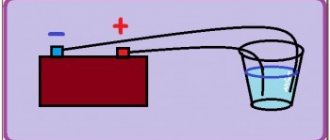
See Figure 6 for conclusions.
Rice. 6. Conclusions
The numbers indicate:
- 1– anode;
- 2 – electrolyte;
- 3 – cathode;
- 4 – current source.
Electroplating
The processes of metal deposition as a result of a chemical reaction under the influence of electric current (electrolysis) are called electroplating. Thus, the world received silver-plated, gilded, chrome-plated or coated with other metals jewelry and parts. This process is used for both decorative and applied purposes - to improve the corrosion resistance of various components and assemblies of mechanisms.
The operating principle of galvanic coating installations is based on the use of solutions of salts of the elements with which the part will be coated as an electrolyte.
In electroplating, the anode is also the electrode to which the positive terminal of the power source is connected, respectively, the cathode in this case is the negative one. In this case, the metal is deposited (reduced) on the negative electrode (reduction reaction). That is, if you want to make a gold-plated ring with your own hands, connect the negative terminal of the power supply to it and place it in a container with the appropriate solution.
Cathode and anode are plus or minus
Anode (translated from ancient Greek - upward movement) is the electrode of any device that is connected to the plus of the power source. The cathode of a diode (translated from ancient Greek as “descending”) is the electrode of any device that is connected to the negative side of the power source.
According to GOST 15596-82:
- the negative electrode during discharge is the anode;
- The positive electrode during discharge is the cathode.
Attention! When charging, everything is the other way around - the cathode is minus, the anode is plus.
Faraday also said that the places where current enters and exits a substance are very important; they must be distinguished from plus and minus.
If there is no current movement, talking about the anode and cathode is pointless.
Electrochemists, when carrying out the electrolysis of metals, call the electrode that is oxidized an anode, and the electrode that is reduced a cathode. For a diode element in the open state, the cathode is the terminal connected to the minus, and the anode is the terminal connected to the plus.
Battery charge
If you look at a battery or regular batteries, you will notice terminals marked “+” and “-”, which are located at opposite ends.
The battery has a metal or plastic frame. Inside, the cathode is connected with positive polarity, and the anode is connected to negative polarity. A barrier separates them from each other, so they do not touch, and the electric charge flows freely between them. This is helped by an electrolyte - a special solution of sulfuric acid.
Battery charging circuit
When a chemical reaction of a charge with an electrolyte takes place on one of the electrical conductors, an oxidation reaction will occur. If you turn on the galvanic component in the electrical network, electrons from the anode will flow to the cathode, producing functionality while chemical interactions occur in the electrolyte. Stop operating the chemical source of electric current only when the chemical components of the electrolyte are used up.
On a note. When a galvanic cell is discharged, the anode has a “-” sign, when the charge - the cathode has a “+” sign.
what are they, how to identify and remember them
Among the terms in electrical engineering there are such concepts as anode and cathode. This applies to power supplies, electroplating, chemistry and physics. The term is also found in vacuum and semiconductor electronics. It denotes the terminals or contacts of devices and what electrical sign they have. In this article we will tell you what an anode and a cathode are, as well as how to determine where they are located in the electrolyzer, diode and battery, which is a plus and which is a minus.
Electrochemistry and electroplating
Electrochemistry has two main branches:
- Galvanic cells - the production of electricity through a chemical reaction. These items include batteries and accumulators. They are often called chemical current sources.
- Electrolysis is the effect of electricity on a chemical reaction; in simple words, some kind of reaction is started using a power source.
Let's consider the redox reaction in a galvanic cell, then what processes take place at its electrodes?
- An anode is an electrode on which an oxidation reaction is observed, that is, it gives up electrons. The electrode at which the oxidation reaction occurs is called a reducing agent.
- A cathode is an electrode on which a reduction reaction occurs, that is, it accepts electrons. The electrode at which the reduction reaction occurs is called an oxidizing agent.
This raises the question - where is the plus and where is the minus of the battery? Based on the definition, the anode of a galvanic cell gives up electrons.
Important! GOST 15596-82 gives the official definition of the names of the terminals of chemical current sources; in short, the plus is on the cathode and the minus is on the anode.
In this case, the flow of electric current through the conductor of the external circuit from the oxidizing agent (cathode) to the reducing agent (anode) is considered. Since electrons in a circuit flow from minus to plus, and electric current vice versa, then the cathode is plus and the anode is minus.
Attention: current always flows into the anode!
Or the same in the diagram:
The process of electrolysis or battery charging
These processes are similar and inverse to a galvanic cell, since here the energy is not supplied through a chemical reaction, but on the contrary, the chemical reaction occurs due to an external source of electricity.
In this case, the plus of the power source is still called the cathode, and the minus the anode. But the contacts of the charged galvanic cell or the electrodes of the electrolyzer will already have opposite names, let's figure out why!
Important! When a galvanic cell is discharged, the anode is minus, the cathode is plus, and when charging it is the other way around.
Since the current from the positive terminal of the power source flows to the positive terminal of the battery, the latter can no longer be the cathode. Referring to the above, we can conclude that in this case, the battery electrodes conditionally change places when charging.
Then, through the electrode of the charged galvanic cell, into which electric current flows, it is called the anode. It turns out that when charging the battery, the plus becomes the anode, and the minus becomes the cathode.
Electroplating
The processes of metal deposition as a result of a chemical reaction under the influence of electric current (electrolysis) are called electroplating. Thus, the world received silver-plated, gilded, chrome-plated or coated with other metals jewelry and parts. This process is used for both decorative and applied purposes - to improve the corrosion resistance of various components and assemblies of mechanisms.
The operating principle of galvanic coating installations is based on the use of solutions of salts of the elements with which the part will be coated as an electrolyte.
In electroplating, the anode is also the electrode to which the positive terminal of the power source is connected, respectively, the cathode in this case is the negative one. In this case, the metal is deposited (reduced) on the negative electrode (reduction reaction). That is, if you want to make a gold-plated ring with your own hands, connect the negative terminal of the power supply to it and place it in a container with the appropriate solution.
In electronics
The electrodes or legs of semiconductor and vacuum electronic devices are also often called anode and cathode. Let's consider the conventional graphic designation of a semiconductor diode in the diagram:
As we can see, the anode of the diode is connected to the positive of the battery. It is called that for the same reason - current flows into this terminal of the diode in any case. On a real element, there is a marking on the cathode in the form of a stripe or dot.
The LED is similar. On 5 mm LEDs the insides are visible through the bulb. The larger half is the cathode.
The situation is also the same with the thyristor, the assignment of the terminals and the “unipolar” use of these three-legged components make it a controlled diode:
For a vacuum diode, the anode is also connected to the positive, and the cathode to the negative, as shown in the diagram below. Although, when reverse voltage is applied, the names of these elements will not change, despite the flow of electric current in the opposite direction, albeit insignificant.
The situation is different with passive elements such as capacitors and resistors. A resistor does not have a separate cathode and anode; current in it can flow in any direction. You can give any name to its conclusions, depending on the situation and the circuit in question. Conventional non-polar capacitors do the same. Less commonly, such a separation by contact names is observed in electrolytic capacitors.
Conclusion
So, let’s summarize by answering the question: how to remember where the plus and minus are between the cathode and the anode? There is a convenient mnemonic rule for electrolysis, battery charging, electroplating and semiconductor devices. These words with similar names have the same number of letters, as illustrated below:
In all of these cases, current flows out of the cathode and flows into the anode.
Don’t be confused by the confusion: “why does the battery have a positive cathode, but when it is charged, it becomes negative?” Remember, for all electronic elements, as well as electrolyzers and galvanics - in general, for all energy consumers, the anode is the terminal connected to the positive. This is where the differences end, now it’s easier for you to figure out what’s a plus and a minus between the terminals of elements and devices.
Finally, we recommend watching a useful video on the topic of the article:
Now you know what an anode and cathode are, and how to remember them quickly enough. We hope the information provided was useful and interesting for you!
How to determine where is the anode and where is the cathode?
When determining the cathode and anode, you must first focus on the direction of the current, and not on the polarity of the power source. Despite the fact that these concepts are closely related to the polarity of the current, they are more determined by the directions of the electricity vectors.
For example, in batteries, when recharging, the roles of the cathode and anode change. This is due to the fact that during charging the direction of the electric current changes. The electrode that acts as an electrode when the battery is operating in power source mode during charging performs the functions of a cathode and vice versa - the cathode turns into an anode.
In Fig. 1, the electrolysis process is depicted, during which the movement of anions (negative ions) and cations (positive ions) occurs. Anions rush towards the anode, and positive cations move towards the cathode.
Rice. 1. Electrolysis
During electrolysis, charge carriers of different signs move, however, by definition, the anode is the electrode into which current flows. In the figure, the anode is connected to the positive pole of the current source, which means that current conditionally flows into this electrode.
Pay attention to Figure 2, which shows a diagram of a galvanic cell. Rice
2. Galvanic cell
Rice. 2. Galvanic cell
The positive terminal of the current source is the cathode, and not the anode, as one might expect. By carefully studying the operating principle of a galvanic cell, you can understand why the anode is the negative pole.
Pay attention to the diagram of the structure of a galvanic current source. The arrows (above) indicate the direction of movement of electrons, but the direction of current is conventionally considered to be movement from plus to minus
That is, when the circuit is closed, the current enters precisely the negative pole, which is the anode on which the oxidation reaction occurs. In other words, the current from the positive electrode passes through the load to the anode, which is the negative pole of the galvanic cell. With a thoughtful approach, everything falls into place.
When determining the positions of the anode and cathode in radio-electronic elements, reference materials are used.
The purpose of the electrodes is indicated by:
- body shape (Fig. 3);
- lead length (for LEDs) (Fig. 4);
- marks on the housings of devices or the anode mark;
- different thickness of diode leads.
Rice. 3. DiodeFig. 4. LED electrodes
Determining the pin assignments of semiconductor diodes can be determined using measuring instruments. For example, all types of diodes (except zener diodes) conduct current in only one direction. If you connect a tester or ohmmeter to a diode and it shows insignificant resistance, then the anode is connected to the positive probe of the device, and the cathode is connected to the negative probe.
If the conductivity type of the transistor is known, then using the same tester you can determine the emitter and collector terminals. Between them, the resistance is infinitely high (there is no current), and between the base and each of them there will be conductivity (only in one direction, like a diode). Knowing the type of conductivity, by analogy with a diode, you can determine where the anode is and where the cathode is, and therefore determine the terminals of the collector or emitter (see Fig. 5).
Rice. 5. Transistor on the circuits and its electrodes
As for vacuum diodes, they cannot be checked by measuring with conventional instruments. Therefore, their pins are located in such a way as to eliminate connection errors. In electronic tubes, the terminals exactly match the location of the contacts of the socket intended for this radio element.
This is interesting: How to solder wires correctly - video, technology, soldering procedure
Concept of anode and cathode
For a better understanding of the terms, we will give definitions of these concepts.
Anode
By this term we mean an electrode through which electric current flows into the device being examined. This implies that the electric current is generated by a flow of positive charges. In reality, metal conductors carry electrons (carriers of negative charges), which move towards the positive pole of the electric current source.
Simply put, we will consider the anode to be the positive electrode, and the cathode to be the negative electrode. When connecting radio elements, their polarity should be observed, following the symbols on the diagrams.
Cathode
This is the electrode through which electric current flows from the device (the conventional understanding of current is implied in the form of a flow of positive charges). Thus, if a wire with a positive potential is connected to the anode, then terminals with negative potentials are connected to the cathode.
The above terms apply to galvanic cells. In electroplating, an anode is an electrode on the surface of which a metal oxidation reaction takes place. The names of the electrodes are found:
- in chemistry;
- physics;
- electrical engineering;
- radio electronics.
When installing radio components, it is very important not to confuse the electrodes. To do this, you need to know how to determine their purpose.
Diode in AC circuit
For those who have forgotten what alternating current is, read. So, in order to consider the operation of a diode in an alternating current circuit, let's draw a diagram. Here we see a frequency generator G, a diode and two terminal blocks X1 and X2, from which we will take a signal using an oscilloscope.
My frequency generator looks like this.
frequency generator
We will take an oscillogram using a digital oscilloscope
The generator produces alternating sinusoidal voltage.
sine wave
What happens after the diode? We connect to terminals X1 and X2 and see this oscillogram.
AC voltage after diode
The diode cut out the bottom part of the sine wave, leaving only the top part.
What happens if we change the diode leads? The scheme will look like this.
alternating current after diode
What do we get at terminals X1 and X2? Let's look at the oscillogram.
alternating current after diode
Wow! The diode cut off only the positive part of the sine wave!
Purpose of the diode
Semiconductor diode elements are present in almost all household electrical appliances. LEDs are used in the production of lighting fixtures and LED TVs.
Semiconductor diodes are classified according to:
- crystal material (silicon, selenium, indium phosphide, germanium);
- sizes (microalloy, spot, flat);
- pn junction production technologies (diffusion, alloy, epitaxial);
- frequency (low-frequency, high-frequency, ultra-high-frequency, impulsive);
- area of use (rectifiers and special ones).
Rectifier diodes are designed to convert alternating voltage to direct voltage. They are installed in the circuit in the form of a diode bridge, which can be used in radio equipment, power supply, charger.
Rectifiers are divided into:
- low current (up to 0.3 ampere);
- average power (0.3-10 amperes);
- power (10-100,000 A, up to 6 kV).
Semiconductor special diode elements:
- varicaps (capacitive diodes);
- thyristors (with an additional output for switching to the open state);
- triacs (current passes in 2 directions);
- Zener diodes (stabilize voltage from 2 volts in a breakdown state, a separate type of stabiistors (normistors) for a voltage of 0.7-2 volts);
- Schottky diodes (for low-voltage circuits paired with a zener diode);
- tunnel diode elements (low negative resistance);
- dinistors (do not contain control electrodes, are mounted in switches);
- magnetic diodes (volt-ampere characteristics change in a magnetic field, mounted in motion sensors, control devices);
- photodiodes (convert light energy into electrical energy);
- LEDs (convert electrical energy into light).
Basics of electroacoustics
Electrovacuum diode is a vacuum two-electrode electron tube. The diode cathode is heated to temperatures at which thermionic emission occurs. When a voltage negative relative to the cathode is applied to the anode, all electrons emitted by the cathode return to the cathode; when a positive voltage is applied to the anode, some of the emitted electrons rush to the anode, forming its current. Thus, the diode rectifies the voltage applied to it. This property of the diode is used to rectify alternating current and detect high frequency signals. The practical frequency range of a traditional vacuum diode is limited to frequencies up to 500 MHz. Disc diodes integrated into waveguides are capable of detecting frequencies up to 10 GHz
A diode is a two-electrode device consisting of a cathode and an anode. One group of diodes is intended for detection, i.e. to isolate low frequency voltage from modulated high frequency oscillations. They are produced with indirectly heated cathodes and have small electrodes designed for low anode currents, low permissible power losses at the anode and a relatively low reverse voltage. The second group of diodes (high power diodes) is designed to rectify alternating voltage, mainly industrial frequency current.
An electric vacuum diode is a vessel (balloon) in which a high vacuum is created. The cylinder contains two electrodes - a cathode and an anode. A directly heated cathode is a straight or W-shaped filament heated by a filament current. An indirectly heated cathode is a long cylinder or box, inside of which an electrically insulated heater coil is laid. Typically, the cathode is embedded inside a cylindrical or box-shaped anode, which in power diodes may have fins or “wings” to dissipate heat. The terminals of the cathode, anode and heater (in indirect incandescent lamps) are connected to external terminals (lamp legs). Operating principle When the cathode heats up, electrons will begin to leave its surface due to thermionic emission. The electrons that leave the surface will prevent other electrons from escaping, resulting in a kind of cloud of electrons forming around the cathode. Some of the electrons with the lowest velocities from the cloud fall back to the cathode. At a given cathode temperature, the cloud stabilizes: the same number of electrons fall on the cathode as fly out of it. Already at zero voltage of the anode relative to the cathode (for example, when the anode is short-circuited to the cathode), a current of electrons flows in the lamp from the cathode to the anode: relatively fast electrons overcome the potential well of the space charge and are attracted to the anode. Current cutoff occurs only when a negative blocking voltage of the order of ?1 V or lower is applied to the anode. When a positive voltage is applied to the anode, an accelerating field appears in the diode, and the anode current increases. When the anode current reaches values close to the cathode emission limit, the current growth slows down and then stabilizes (saturates). The current-voltage characteristic (CVC) of an electric vacuum diode has 3 characteristic sections:
1. Nonlinear section. In the initial section of the current-voltage characteristic, the current slowly increases with increasing voltage at the anode, which is explained by the counteraction of the volume negative charge of the electron cloud to the anode field. Compared to the saturation current, the anode current at U_a = 0 is very small (and not shown in the diagram). Its dependence on voltage increases exponentially, which is caused by the spread of initial electron velocities. To completely stop the anode current, it is necessary to apply some anode voltage less than zero, called a blocking voltage. 2. Section of the law of the power of three second. The dependence of the anode current on voltage is described by the law of the power of three second ones: j=g \cdot U_a^{3/ 2}, where g is a constant depending on the configuration and size of the electrodes (perveance). In the simplest model, the perveance does not depend on the composition and temperature of the cathode; in fact, it increases with increasing temperature due to uneven heating of the cathode. 3. Saturation section. With a further increase in the voltage at the anode, the increase in current slows down and then stops completely, since all the electrons escaping from the cathode reach the anode. A further increase in the anode current at a given incandescent value is impossible, since this requires additional electrons, and there is nowhere to get them, since all the emission of the cathode has been exhausted. The steady-state anode current is called the saturation current. This section is described by the Richardson-Deshman law: j = AT^2 \exp \left( -{e \varphi \over kT} \right), where A={4\pi mek^2 \over h^3}=120 { \text{A} \over {\text{cm}^2 \text{K}^2}} is the universal thermionic Sommerfeld constant. The anode's current-voltage characteristic depends on the filament voltage - the higher the heat, the greater the slope of the current-voltage characteristic and the greater the saturation current. Excessive increase in filament voltage leads to a decrease in lamp life. The main parameters of the vacuum diode include:
- Slope of the current-voltage characteristic: S={dI_a \over dU_a} - change in the anode current in mA per 1 V change in voltage.
- Differential resistance: R_i={1 \over S}
- Maximum permissible reverse voltage. At a certain voltage applied in the opposite direction (that is, the polarity of the cathode and anode is changed), a diode breakdown occurs - a spark jumps between the cathode and anode, which is accompanied by a sharp increase in current strength.
- Blocking voltage is the voltage required to stop the current in the diode.
- Maximum permissible power dissipation.
- Slopeness and internal resistance are functions of the anode voltage and cathode temperature.
If the cathode temperature is constant, then within the “three-seconds” section the slope is equal to the first derivative of the “three-seconds” function.
They are produced with both direct and preheated (indirect) cathodes and are divided into two classes: low-voltage and high-voltage. Low-power high-frequency diodes designed for detecting high-frequency oscillations include diodes of the 6Х6С, 6Х2П, 6Х7Б types, as well as diodes in combination with triodes and pentodes: 1Б1П, 1Б2П, 6Б2П, 6Б8С, 6Г2 and 6Г7. Kenotrons designed for rectifying power frequency voltage in rectifiers of radio equipment include: 5Ts3S, 5Ts4S, 5Ts9S, 6Ts4P and 6Ts5S.
Diode designations
- The first element is a number indicating (rounded) the filament voltage.
- The second element is a letter indicating the type of lamp: D - single diodes. X - double diodes. C - kenotrons (depending on the number of anodes).
- The third element is a number indicating the serial number of the device type with the remaining designation elements being the same.
- The fourth element is a letter indicating the design. Lamps in a metal cylinder do not have this letter. C - glass bottle; P-finger lamp; B - miniature lamp with a diameter of 6 mm; F - “acorn” type lamps, especially for VHF; L - lamps with a locking base, eliminating the possibility of falling out of the socket when shaking.
In electronics
The electrodes or legs of semiconductor and vacuum electronic devices are also often called anode and cathode. Let's consider the conventional graphic designation of a semiconductor diode in the diagram:
As we can see, the anode of the diode is connected to the positive of the battery. It is called that for the same reason - current flows into this terminal of the diode in any case. On a real element, there is a marking on the cathode in the form of a stripe or dot.
The LED is similar. On 5 mm LEDs the insides are visible through the bulb. The larger half is the cathode.
The situation is also the same with the thyristor, the assignment of the terminals and the “unipolar” use of these three-legged components make it a controlled diode:
For a vacuum diode, the anode is also connected to the positive, and the cathode to the negative, as shown in the diagram below. Although, when reverse voltage is applied, the names of these elements will not change, despite the flow of electric current in the opposite direction, albeit insignificant.
The situation is different with passive elements such as capacitors and resistors. A resistor does not have a separate cathode and anode; current in it can flow in any direction. You can give any name to its conclusions, depending on the situation and the circuit in question. Conventional non-polar capacitors do the same. Less commonly, such a separation by contact names is observed in electrolytic capacitors.
Application
Electrodes as anode and cathode are most often used:
- in electrochemistry;
- vacuum electronic devices;
- semiconductor elements.
Let us consider in general terms the areas of application of anodes and cathodes.
In electrochemistry
In this field, anode and cathode are key concepts in the process of electrochemical reactions used mainly for the reduction of metals. Such reactions are called electrolysis. The use of electrolysis processes makes it possible to obtain pure metals, since atoms of only the metal whose positive ions are contained in the electrolyte solution are formed at the cathode.
Using electrolysis, a very thin zinc coating is applied to steel sheets and parts of any configuration. Galvanic coating effectively protects the metal from corrosion.
In vacuum electronic devices
Examples of vacuum devices are electronic tubes, cathode ray tubes, and television picture tubes. They work on the same principle: The heated cathode emits electrons, which rush to the anode with a high positive electrical potential.
The formation of electrons on a hot electrode is called thermionic emission, and the electric current arising between the cathode and anode is called thermionic current. The value of such devices is that they conduct current only in one direction - from the cathode to the anode.
Adding a grid between the electrodes allows you to adjust the current parameters over a wide range by changing the voltage on the grid. Such vacuum tubes are used as signal amplifiers. At this time, vacuum devices are used quite rarely, since they are successfully replaced by miniature semiconductor diodes and transistors, often made on a single crystal in the form of a microcircuit.
In semiconductor devices
Electronic parts based on semiconductors are valued for their low current consumption and small size. They have almost driven vacuum tubes out of use. The terminals of semiconductor devices are traditionally called anodes and cathodes.
Despite all the advantages of semiconductors, these devices have a drawback - they are “noisy”. In high power amplifiers this noise becomes noticeable. High-quality amplification equipment still uses vacuum tubes.
Cathode-ray picture tubes in modern TVs are being replaced by LED-backlit screens. They are more economical, perfectly convey the color palette, and make the receiver almost flat.
What is a diode
A semiconductor diode or simply a diode is a radio element that allows electric current to pass in only one direction and blocks its passage in the other direction. In a hydraulic analogy, a diode can be compared to a check valve: a device that allows fluid to flow in only one direction.
check valve
A diode is a radio element with two terminals. Some diodes look almost the same as resistors:
And some look a little different:
There are also SMD versions of diodes:
The terminals of the diode are called anode and cathode. Some people mistakenly call them “plus” and “minus”. This is not true. You can't say that.
In the diagrams the diode is designated as follows
It can only pass electric current from the anode to the cathode.
LED pinout by power supply
The advantage of this method is that it can be used for light-emitting diodes with any parameters (voltage drop and current rating). For such a check, it is better to use a power source with a current limit setting, or at least with its indication for control. Otherwise, the sensitive semiconductor device may be damaged.
Incorrect polarity of LED connection to the voltage source - no light.
If you have an adjustable source, you need to randomly connect an LED to its output and apply voltage, gradually increasing it from zero. The power supply should not be raised above 2-3 V so that the element does not burn out. If it does not light up, you need to remove the voltage and switch the terminals in the opposite way.
The correct polarity of connecting the LED to the voltage source - the LED lights up.
By gradually increasing the voltage, you can visually determine the moment the LED lights up. In this case, the positive terminal of the source is connected to the anode, and the negative terminal is connected to the anode of the radiating element.
If there is no regulated source, then you can try to use an unregulated power supply with a voltage obviously higher than the LED supply voltage. In this case, tests are carried out only through a 1-3 kOhm resistor connected in series with the semiconductor device.
If in both cases the LED does not light up, you can try testing with increased voltage. If the element is faulty, this will not harm it, and if it is designed for increased voltage, then it will be possible to find out the correct location of the terminals.
We recommend: How to find out how many volts an LED is
Links
Wikimedia Foundation. 2010.
Synonyms
See what “Cathode” is in other dictionaries:
- (Greek kathodos descent). The pole of a galvanic pair opposite the anode. Dictionary of foreign words included in the Russian language. Chudinov A.N., 1910. CATHODE in galvanic elements and a volt column, the negative pole, i.e. the end... ... Dictionary of foreign words of the Russian language
cathode
- a, m. cathode f. <English cathode < gr. kathodos way down, descent. An electrode connected to the negative pole of a current source (as opposed to the anode). BAS 1. In the operation of devices such as a galvanic battery, there is no polarity and there will be... ... Historical Dictionary of Gallicisms of the Russian Language
cathode
— cathode A flat piece obtained by electrolysis, intended for remelting. cathode Negative electrode of an x-ray tube [Non-destructive testing system. Types (methods) and technology... ... Technical Translator's Directory
- (from the Greek kathodes, downward movement, return; the term was proposed by the English physicist M. Faraday in 1834), 1) the negative electrode of an electric vacuum or gas discharge device, serving as a source of electrons, which ensure the conductivity of the interelectrode pr... ... Physical encyclopedia
Emitter Dictionary of Russian synonyms. cathode noun, number of synonyms: 4 thermal cathode (1) ... Dictionary of synonyms
CATHODE
— CATHODE, the electrode connected to the negative terminal of the battery. If two metal plates connected to the poles of a battery are immersed in a liquid, the difference between the cathode and the anode will be as follows: if the plates from which the electrodes are made ... Great Medical Encyclopedia
cathode
— electric vacuum device; cathode An electrode, the main purpose of which is usually the emission of electrons during an electrical discharge ... Polytechnic terminological explanatory dictionary
- (from the Greek kathodos move down, return), an electrode of an electronic or electrical device or device (for example, an electrovacuum device, a galvanic cell, an electrolytic bath), characterized by the fact that the movement ... ... Modern encyclopedia
- (from the Greek kathodos, move down, return), in a broad sense, the electrode of various radio and electrical devices or instruments (electron tubes, galvanic cells, electrolytic baths, etc.), characterized by the fact that movement ... ... Big Encyclopedic Dictionary
CATHODE, a negatively charged ELECTRODE in an electrolytic cell or ELECTRONIC TUBE. In the process of ELECTROLYSIS (where electrical energy is used to carry out chemical changes), positively charged ions are attracted to it... ... Scientific and technical encyclopedic dictionary
CATHODE, cathode, man. (Greek kathodos return) (physical). Negative electrode; ant. anode. Ushakov's explanatory dictionary. D.N. Ushakov. 1935 1940 ... Ushakov's Explanatory Dictionary
Books
Methods of experimental physics in selected technologies for the protection of nature and humans: Monograph, Korzhavy Alexey Pavlovich. The book outlines selected methods of experimental physics, created on the basis of vacuum microwave, gas-discharge lasers and sealed-type devices to protect the natural environment and...
Only in one direction. Once upon a time, tube diodes were used. But now semiconductor diodes are mainly used. Unlike lamp ones, they are much smaller in size, do not require filament circuits, and are very easy to connect in different ways.
Symbol of the diode in the diagram
The figure shows the symbol of the diode in the diagram
.
The letters A and K respectively indicate the diode anode
and
diode cathode
.
The anode of a diode is the terminal that is connected to the positive terminal, either directly or through circuit elements. The diode cathode is the terminal from which a positive potential current emerges and then, through circuit elements, enters the negative electrode of the current source. Those. The current through the diode
goes from the anode to the cathode. But in the opposite direction the diode does not pass current. If a diode is connected to one of its terminals, then at its other terminal a constant voltage is obtained with a polarity depending on how the diode is connected. If it is connected by the anode to an alternating voltage, then we will receive a positive voltage from the cathode. If it is connected to the cathode, then a correspondingly negative voltage will be received from the anode.
What is a semiconductor diode - AC rectifier
Diodes are two-electrode devices that have one-way conductivity of electric current. This main property is used, for example, in rectifiers, where diodes convert alternating current from the mains into direct current to power radio equipment, in receivers - to detect modulated high-frequency oscillations, that is, convert them into low (sound) frequency oscillations.
A clear illustration of this property of a diode can be the following experiment (Fig. 12). In a circuit made up of a 3336L battery and a light bulb from a flashlight (3.5 V X 0.26 A), connect any planar diode (in Fig. 12 it is indicated by the Latin letter V), for example, from the D226 or D7 series, but so that the anode of the diode, designated conventionally by a triangle, would be connected directly or through a light bulb to the positive pole of the battery, and the cathode, designated by the dash to which the corner of the triangle adjoins, to the negative pole of the battery. The light should be on.
Change the polarity of the battery to reverse - the light will not light. If the resistance of a diode is measured with an ohmmeter, depending on how you connect it to the terminals of the device, the ohmmeter will show different resistance: in one case it is small (units or tens of ohms), in the other it is very large (tens and hundreds of kilo-ohms). This confirms the one-way conductivity of the diode.
How does a diode work and how does it work? It has two electrodes: the cathode is negative and the anode is positive (Fig. 13). The cathode is a plate of germanium, silicon or some other semiconductor with electronic conductivity, or abbreviated n-type semiconductor (n is the initial letter of the Latin word negativus - “negative”), and the anode is part of the volume of the same plate, but so called hole conductivity, or abbreviated p-type semiconductor (p is the initial letter of the Latin word positivus - “positive”).
A so-called p-n junction is formed between the electrodes - a boundary zone that conducts current well from the anode to the cathode and poorly in the opposite direction (the direction of the current is taken to be the direction opposite to the movement of electrons).
The diode can be in one of two states: open, that is, passing, or closed, that is, non-passing. The diode is open when a direct voltage Upr is applied to it, otherwise, its anode is connected to the plus of the voltage source, and the cathode is connected to the minus.
In this case, the resistance of the pn junction of the diode is small and a direct current IPre flows through it, the strength of which depends on the load resistance (in our experience, a flashlight bulb).
With a different polarity of the supply voltage, reverse voltage Urev is applied to the pn junction of the diode. In this case, the diode is closed, its resistance is high and only a small reverse diode current Irev flows in the circuit.
The dependence of the current passing through the diode on the value and polarity of the voltage on its electrodes is best judged by the current-voltage characteristic of the diode, which can be measured experimentally (Fig. 14).
Connect a wirewound variable resistor 7?r with a resistance of 50... 100 Ohms to the fresh element 332 or 343, and between its slider and the bottom (according to the diagram) extreme terminal, connect a series-connected germanium plane diode (for example, the D7 series with any letter index), milliammeter RA2 and a resistor Rolim with a resistance of 10...20 Ohms, limiting the current in the circuit to 100...150 mA.
The diode must be connected in the forward direction, that is, with the anode towards the positive pole of the element. A DC voltmeter PU1 is connected in parallel to the diode, turned on for a measurement limit of up to 1 V and recording the voltage supplied to the electrodes of the diode.
Place the motor of the variable resistor, which acts as a voltage divider, in the lowest (according to the diagram) position and then, carefully watching the arrows of the instruments, very slowly move it towards the upper position. Record the milliammeter readings at diode voltages of 0.05, 0.1, 0.15 V, etc., up to a voltage of 0.4...0.5 V every 0.0 V, and then use these data to build a graph on graph paper (Fig. 15).
On the horizontal axis to the right, plot the direct voltages on the diode (Upr), and on the vertical axis up, plot the corresponding direct currents in the circuit (Ipr). By connecting the points of intersection of the values of electrical quantities, you will thus construct a direct branch of the current-voltage characteristic of the diode (in Fig. 15 there is a solid line). True, it is not entirely accurate, especially in the initial part, since a small current flows through the voltmeter, but it is still close to real.
What can this graph tell you? At zero voltage on the diode and the current in the circuit in which it is connected is zero. When forward voltage appears, the diode opens and passes forward current through itself.
At a voltage of 0.05 V, the forward current does not exceed 0.1...0.2 mA, at a voltage of 0.1 V - 0.6...0.8 mA, and at a voltage of 0.2...0.3 V, when the current-voltage characteristic begins to rise steeply, the current already reaches 40...50 mA. A small increase in voltage, but how sharply the current increases!
But it is impossible to significantly increase the voltage on the diode and thereby increase the current through it: due to an excessively large current, thermal breakdown occurs, and the diode loses its property of one-way conductivity. To prevent this from happening during the experiment, a limiting resistor R0gr was included in the circuit.
Now change the polarity of the diode to reverse and increase the voltage on it in the same way. What does a milliammeter show? Its needle is near the zero mark. Replace the element with a 3336L battery, connect two or three of these batteries in series. The voltage across the diode increases. But it's the opposite. The diode is closed, so there is practically no current in the circuit.
Reverse branch of the current-voltage characteristic on £is. 15 is shown with a dashed line. It runs almost parallel to the Uarb axis. But at some sufficiently large reverse voltage, it turns sharply and goes down. This is the limit at which the diode is struck by reverse voltage and, as with thermal breakdown, fails.
From the constructed current-voltage characteristic it is clear that the diode current Ipr is hundreds and thousands of times greater than the current Irev. So, for example, for a diode with such a current-voltage characteristic, at a forward voltage of 0.3 V, the current IRev is approximately 70 mA, and at a reverse voltage of 100 V, the current Irev does not exceed 200 μA. It was for this reason that the light bulb did not light up in the second part of the first experiment.
If we neglect the small reverse current (which is what is done in practice), which for serviceable planar diodes does not exceed tenths of a milliampere, and for point diodes is even less, then we can assume that the diode is a one-way conductor of current.
A current-voltage characteristic similar to that shown in Fig. 15, also has a silicon diode, for example, the D226 series, but the direct branch of its characteristics seems to be shifted to the right. This is explained by the fact that a silicon diode opens at a forward voltage of about 0.5 V, and not at 0.1...0.15 V, like a germanium diode. At a lower voltage, the diode is closed and practically no current flows through it. Check this out experimentally.
But remember - a diode, be it germanium or silicon, planar or point, cannot be turned on in the forward direction without a load: it will quickly fail due to the unacceptably large current that will flow through it.
What if the diode is connected to an alternating current circuit? It will work as a rectifier, as the following experience can confirm.
Before starting this experiment, I would like to remind you that the electrical lighting network with which you will have to deal is fraught with hidden dangers. Neglect of them can lead to serious consequences.
How to prevent troubles that the power grid can cause? First of all, do not forget that it is under high voltage, which is dangerous for you. Never touch the bare wires and contact sockets of the power socket with your hand or tool.
And if you need to insulate a damaged section of a wire or tighten the screws in a power socket, ask your elders or yourself to carefully remove the fuses (“plugs”) on the distribution board to de-energize the network. Only then eliminate defects or malfunctions.
Before inserting the plug of an electric soldering iron or transformer needed to power a receiver or other radio device from the mains into a power socket, carefully inspect them to see if there are any bare areas, shorted wires, or loose or loose contacts. If everything is in order, turn it on, but again be careful, without touching the plug pins.
We recommend purchasing a portable distribution block with several plug sockets and connecting devices to the network through it. Let's continue the experiments with a diode (Fig. 16).
In the circuit of the secondary (II) winding of transformer T, which lowers the voltage of the electric lighting network to 3...5 V, connect a diode D226 or D7 with any letter index or any similar planar diode, and in series with it a light bulb from a flashlight. Connect the primary (I) winding of the transformer to the network (via fuse F for a current of 0.25 A).
If the light bulb is lit with a significant overheating of the filament, then connect a resistor to the circuit that limits the current in it to 0.2...0.3 A. Calculate the resistance of this resistor using Ohm's law.
How do you know what current flows through the filament of a light bulb - alternating or direct? This can be done using a DC voltmeter. Connect the voltmeter parallel to the light bulb (PU1 in Fig. 16), but so that its positive probe is connected to the conductor going to the cathode of the diode. The device will show some voltage. If the device is connected to a light bulb in a different polarity, its needle will deflect in the opposite direction. This experience already confirms that a current flows through the light bulb in one direction, that is, constant.
The type of current can also be judged by its magnetic field. On a spool of thread, wind 300...350 turns of wire with a diameter of 0.2...0.3 mm in enamel, silk or paper insulation (PEV, PEL, PELSHO 0.2...0.3), making a tap from 120...150- th turn (the tap will be needed for experiments at the fifth workshop). You will get an inductor (Fig. 17, a) with a wood frame.
Connect it to the secondary winding circuit of the same step-down transformer (in Fig. 17.6 - coil L) in series with a diode and an incandescent light bulb. As in the previous experiment, the light should be on.
Bring a magnetic needle (compass) to the coil - it will immediately be located along the axis of the coil, pointing to its magnetic poles. This means that a direct current flows through the coil, otherwise the magnetic needle would remain oriented towards the magnetic poles of the Earth.
Reverse the connection of the diode leads - the magnetic needle will immediately rotate 180°. Consequently, when the polarity of the diode changes, the current in the circuit in which it is connected also changes its direction.
What happened in the external circuit of the secondary winding of the transformer when a diode was connected to it? By passing current well in one direction, the diode thereby rectifies alternating current.
As a result, the current in the circuit became pulsating (see graph in Fig. 16) - constant in direction, but varying in magnitude with the frequency of the alternating current. Its magnetic field also became constant, but also pulsating. By changing the switching on of the diode, you thereby changed the direction of the current in the coil and the location of its magnetic poles.
What is the role of the light bulb in this experiment? Firstly, it serves as an indicator that the power is turned on, and secondly, it limits the current in the external circuit, protecting the diode from overload.
If you have a radio, turn it on. Regardless of the setting, when the coil is disconnected from the secondary winding circuit of the transformer, a characteristic crackling noise is heard in the receiver's loudspeaker. It is created by electromagnetic oscillations excited by a weak electric spark that occurs in a circuit with a coil at the moment the current is turned off.
Leave only a diode and a light bulb in the secondary winding circuit of the transformer (as in Fig. 16). The light remains on. Measure the voltage on the winding with an AC voltmeter (voltmeter PU2 in Fig. 16), and measure the voltage on the light bulb with a DC voltmeter PU1. The voltage on the light bulb is almost half that on the winding.
The conversion of alternating current by a diode occurs as follows. An alternating voltage with a frequency of 50 Hz is induced in the secondary winding of the transformer. With positive half-cycles at its upper terminal (shown in Fig. 16 with a “+” sign), the diode opens. At these moments of time, direct diode current Ipr flows through the diode and its load (light bulb).
During negative half-cycles at the anode, the diode closes and only a slight reverse current Irev flows in the circuit. The diode seems to cut off most of the negative half-waves of alternating current (shown in dashed lines in the graph of Fig. 16), as a result, a pulsating current flows through the rectifier load - a current of one direction, but varying in strength with a frequency of 50 Hz. A graph of such a current can only be seen on the oscilloscope screen.
The conductor connected to the cathode of the diode is the terminal of the positive pole of the rectifier, and the free end of the secondary winding of the transformer is the terminal of the negative pole of the rectifier.
The result is a simple AC rectifier, the load of which is an incandescent light bulb. And the constant voltage across the load is less than the alternating current voltage on the secondary winding, because the current flows through it in half waves.
Due to the fact that in the external section of the rectifier circuit (in our experience - a light bulb) current flows mainly only with positive half-cycles of the voltage at the anode of the diode, the rectifier is called single-half-period.
Such a rectifier can find practical application, for example, for powering a DC microelectric motor, for charging small-sized batteries (type D~0.06, D-0.2). As an experiment, try connecting to it (with the same poles) a completely discharged 3336L battery. After 30...40 minutes, disconnect the battery from the rectifier and connect a light bulb from a flashlight to it. The light will light, but not for long: the electrical charge received by the battery will quickly be used up.
Another experiment with a half-wave rectifier. Connect headphones to the output of the rectifier, loaded with a light bulb (in Fig. 18 - B). In phones you will hear a low-pitched sound corresponding to the pulsation frequency of the rectified current (50 Hz).
It is called the AC background. Then, without turning off the phones, connect a capacitor with a capacity of 5...10 μF to the output of the rectifier (capacitor C in Fig. 18™).
If this capacitor is electrolytic, its positive plate must be connected to the positive side, and the negative plate to the negative side of the rectifier. In this case, the light bulb will burn a little brighter, because the voltage at the output of the rectifier has increased (check with a voltmeter), and the background level will become lower. The tonality of the audio being listened to on phones remains the same.
What is the role of the capacitor in this experiment? At times when the diode is open, the capacitor is charged to the maximum (amplitude) value of the rectified voltage pulses, and when the diode is closed, it is discharged through the rectifier load.
The ripples of the rectified voltage are “smoothed out”, as a result, the average value of the current in the external circuit increases slightly, and the background alternating current decreases.
Increasing the capacitance of the capacitor improves the smoothing of rectified current ripples, and the background weakens. But with a half-wave rectifier, only one half-cycle of alternating current is usefully used. In order to use both half-cycles of alternating current with the same step-down transformer, two or four diodes of the same type must operate in the rectifier.
Carry out an experiment with a rectifier using four diodes connected in a so-called bridge circuit. Diodes can be of the D226, D7 series with any letter index. Connect them together and connect them to the secondary winding of the same step-down transformer exactly according to the diagram shown in Fig. 19.
If the polarity or switching sequence of the diodes is incorrect, the experiment will fail and some of the diodes may be damaged. Diodes connected in this way form a rectifier bridge, and each of the diodes forms a bridge arm. Between points A and B, turn on the light bulb I from a flashlight, and in series with it - a resistor Rorp, limiting the current & of this diagonal of the bridge to 0.25...0.3 A.
Turn on the power. Is the light on? It should burn. Measure the voltage on the secondary winding of the transformer with an AC voltmeter, and measure the voltage with a DC voltmeter between points A and B, which are the output contacts of the rectifier. Compared to a half-wave rectifier, the output voltage almost doubled.
In such a rectifier, during each half-cycle of the alternating voltage, two diodes of opposite arms operate alternately, connected in series with each other, but opposite to the second pair of diodes.
When there is a positive half-cycle at the upper (according to the diagram) terminal of the secondary winding of transformer T, the current will flow through diode VI, load H, resistor Rorp and diode V3 to the lower terminal of the secondary winding. Diodes VI and V4 are closed at this time. During another half-cycle of the alternating voltage, the current in the rectifier load flows in the same direction, and in the rectifier itself - through the diodes V4 and VI that are open at this time.
Thus, both half-cycles of alternating current are used here, which is why such rectifiers are called full-wave. The direct current voltage at their output is approximately equal to the alternating voltage acting in the entire secondary winding of the transformer,
Literature: Borisov V. G. Workshop for a beginner radio amateur. 2nd ed., revised. and additional 1984.
Diode in DC circuit
As we have already said, a diode allows electric current to pass in only one direction. To show this, let's put together a simple diagram.
direct connection of the diode
Since our incandescent lamp is 12 Volt, therefore, we also set the value on the power supply to 12 V and assemble the entire electrical circuit according to the diagram above. As a result, our light bulb burns perfectly. This indicates that electric current is passing through the diode. In this case, the diode is said to be connected in the forward direction.
direct diode
Let's now change the leads of the diode. As a result, the diagram will take this form.
reverse diode switching
As you can see, the light bulb does not light up, since the diode does not allow electric current to pass through, that is, it blocks its passage, although the power source produces its honest 12 Volts.
reverse diode switching
What conclusion can be drawn from this? A diode conducts direct current in only one direction.
The property of a pn type semiconductor, to conduct electric current in one direction and not in the opposite direction, has found application in an electronic device called a “Diode”.Figure 1 shows the direct connection of the diode in which the diode conducts electric current, and Figure 2 shows the reverse connection of the diode in which the diode does not conduct electric current. This is how a diode behaves when connected to a DC circuit. The currents and their corresponding voltages are called forward current (when the diode is turned on in the conducting direction) and the corresponding voltage is called forward voltage. During reverse switching, the currents and voltages are respectively called reverse current and reverse voltage.
On the graph, the volt-ampere characteristic looks as shown in the figure. Since diodes are used in various fields of radio and electronics, the main parameters of diodes are the forward current Irev and the corresponding forward voltage Urev, the permissible reverse voltage Urev and the corresponding reverse current Irev. The main purpose of diodes is to convert alternating current into direct current. Let's consider how, for example, to obtain direct current from alternating current to power a radio receiver.
The step-down transformer (see figure) converts the 220V alternating voltage of the lighting network into a low 6V alternating voltage (graph 1). Since the diode passes current only in one direction, after the diode we will get a pulsating voltage only with positive half-waves (Graph 2). In order to obtain a constant voltage, it is necessary to turn on a capacitor at the output of the rectifier.
When a positive half-wave of alternating current passes through the diode, the capacitor is charged; at the moment of the negative half-wave of alternating current, there is no voltage at the output of the diode (point A), but since the capacitor is charged, a constant voltage is present at its terminals. The capacitor is gradually discharged to the load, in the next positive half-cycle the process is repeated, and the voltage graph at the output of the rectifier (point A) looks as shown in the figure. We see that at the output of the rectifier there is not an ideal constant voltage, but a constant voltage with small ripples. The larger the capacitor capacity, the smaller the ripple. Typically, rectifiers use high-capacity electrolytic capacitors (from 1000 microfarads or more). You can smooth out the ripples even more if you use a U-shaped filter (which we talked about in the topic “Inductance”) consisting of 2 capacitors C1 and C2 and an inductor L1.
Another important application of diodes is signal detection. When we studied the topic “Oscillating circuit,” we said that the high-frequency signal from a radio station isolated by an oscillating circuit is fed to the detector to convert the radio station signal into an audio frequency signal. Only high-frequency signals travel well on the air. High-frequency signals from radio stations are modulated by low-frequency (audio) frequency signals. Let's consider a signal modulated in amplitude. Such a signal is called “Amplitude Modulated” - AM.
The high frequency (carrier frequency) is changed in amplitude by the low frequency signal (envelope). Unlike the LF signal, the frequency of the HF signal does not change over time. In the detector, after the diode, the LF and HF signals are separated.
The HF signal passes through capacitor C1 to ground with virtually no interference, and the LF audio signal passes to a low-frequency amplifier, where it is amplified and fed to a loudspeaker. For normal operation of the diode, a load must be switched on at the detector output. In our case, this is resistance Rн.
The purpose of diodes is not only to rectify alternating current and detect signals. There are, for example, diodes as voltage stabilizers. Stabilizing diodes are called "zener diodes". The operating principle of such diodes is based on the breakdown of the pn junction when a reverse voltage (when the diode does not conduct electric current) is applied to the diode.
At a certain voltage (Upr), the pn junction breaks down, the reverse current increases sharply and the voltage on the diode remains unchanged (see graph). The zener diode connection circuit is shown in the figure.
The limiting resistor Ro is included in the circuit so that it creates a voltage drop Ur equal to the difference between the input voltage Uin and the output voltage Uout: Ur = Uin - Uout. Obviously, a voltage stabilizer on a zener diode cannot deliver more power to the load, so such stabilizers are used as a reference voltage source for more powerful stabilizers, for example, on high-power transistors. When the voltage is removed from the zener diode, the properties of its pn junction are restored. The reference books for zener diodes indicate the breakdown current of the pn junction Ist and the stabilization voltage Ust.
Also included in a broad class of diodes are light-emitting diodes, which, when a small direct current passes through them, emit light waves (from infrared to violet).
LEDs are used mainly as economical indicators in various household and industrial appliances, as well as in remote controls (infrared) for various electronic equipment (TVs, stereos, etc.). So, we know that the use of diodes in electronic equipment is very diverse, such as rectification of alternating current, signal detection, voltage stabilization, light indicators, and so on. The figure shows the most common types of diodes.
What types of diodes are there?
Schematic representation of diodes
Photo of the rectifier diode
A) The photo shows the diode we discussed above.
Zener diode image on the diagram
B) This figure shows a zener diode (foreign name Zener diode), it is used when turning the diode back on. Main goal: maintaining voltage stable.
Two-node zener diode - diagram image
B) Double-sided (or two-anode) zener diode. The advantage of this zener diode is that it can be turned on regardless of the polarity.
D) Tunnel diode, can be used as an amplification element.
D) Reversed diode, used in high-frequency detection circuits.
E) Varicap, used as a variable capacitor.
G) Photodiode, when the device is illuminated, a current arises in the circuit connected to it due to the formation of pairs of electrons and holes.
H) LEDs, well-known to everyone, and probably the most widely used devices, after conventional rectifier diodes. They are used in many electronic devices for display and more.
Rectifier diodes are also produced in the form of diode bridges, let's look at what they are - these are four diodes connected to produce direct (rectified) current in one housing. They are connected using a bridge circuit, standard for rectifiers:
Diode bridge circuit
They have four marked terminals: two for connecting alternating current, and a plus and a minus. The photo shows the KTs405 diode bridge:
Now let's take a closer look at the area of application of LEDs. LEDs (or rather LED lamps) are produced by industry and for indoor lighting, as an economical and durable light source, with a base that allows them to be screwed into a regular incandescent lamp socket.
LED lamp photo
LEDs come in different packages, including SMD.
So-called RGB LEDs are also produced, inside them there are three LED crystals with different luminescence Red-Green-Blue, respectively Red - Green - Blue, these LEDs have four outputs and allow you to get any color visible by mixing colors.
Connecting RGB strip
These SMD LEDs often come in strip form with resistors already installed and allow them to be connected directly to a 12-volt power source. You can use a special controller to create lighting effects:
When used, LEDs do not like to be supplied with a supply voltage higher than that for which they are designed and can burn out immediately or after some time, so the voltage of the power source must be calculated using formulas. For Soviet LEDs of the AL-307 type, the supply voltage should be approximately 2 volts, for imported ones 2-2.5 volts, naturally with current limitation. To power LED strips, if a special controller is not used, a stabilized power supply is required. Material prepared by AKV.
To create efficient electronic circuits with diodes, a minimum amount of knowledge about their structure and operating principle is required. Before starting soldering, it is imperative to determine where the anode and cathode are on these elements. A visual inspection may not be enough if electronic components were purchased without technical documentation or soldered from old equipment. To check, you definitely need a tester with different operating modes and a power source with a voltage of 3-6 volts.
LED polarity: how to determine plus and minus
When using LEDs in creating various circuits, they must be installed correctly. Soldering in most cases does not create problems; determining the polarity is a little more difficult if you do not have experience working with testing equipment.
How to determine polarity with a multimeter tester
The easiest way to check the LED is with a multimeter. When connecting the pins in the “dialing” mode to the electrodes, you can get 2 results: the LED lights up and displays a number on the screen depending on the color of the radiation, or shows a very large number. With the first option, we can conclude that the light source is working and connected to the multimeter correctly (plus to plus, minus to minus).
The second method of using a multimeter is to switch to resistance testing. If the red probe touches the plus, the black probe touches the minus, a value in the range of 1600–1800 appears on the screen.
Attention! If the LED is broken (passes voltage in two directions), the number “1” appears on the screen. If there is a break, a very large resistance value appears on the screen, regardless of the location of the probes.
If the multimeter has a PNP compartment, the E (emitter - “+”) and C (collector – “-”) compartments are required to determine the polarity of the LED. The light source glows if the cathode is inserted into “C” and the anode into “E”.
If an NPN multimeter compartment is used, the LED will light if the legs are swapped.
By appearance
In the production of LEDs, different housings are used. DIP elements with a cylindrical body of various diameters are widely used. There are many surface mount SMDs being manufactured. Ultra-bright light sources differ in the size of their housings and crystals. An experienced radio amateur determines the cathode and anode by external signs.
- longer anode leg;
- the silhouette in the flask is smaller at the anode, the shape of the cathode resembles a flag;
- a source with a power of more than 1 W has a “+” marking on the anode leg.
Attention! If the DIP LED has already been installed in some device and soldered, the dimensions of the legs may change. Plus and minus are determined by the size of the crystal in the flask or by testing with a multimeter.
- the cathode is indicated by a cut on the body;
- the heat sink on the back of the case is located closer to the anode;
- The “P” pictogram is facing the anode with the top shelf, the top of the “T” pictogram is facing the cathode.
Some manufacturers put certain symbols on SMD LED housings that allow you to determine the polarity.
Important! There are SMDs made according to a different principle (some manufacturers do not comply with the standards). On complex models there are always symbols “+” and “−”.
Any non-semiconductor radio tube (zener diode) consists of an anode, cathode and grid. The cathode is always a heated electrode made in the shape of a cylinder. During thermionic emission, electrons move to the anode (box or plate) - a tungsten conductor with high resistance.
To determine the performance of the zener diode, use a multimeter in ringing mode. If a positive probe is applied to the anode, a negative probe to the cathode, the zener diode will open and the voltage value will be visible on the screen. If you swap the probes, the zener diode will close and the number 1 will appear on the screen.
By supplying power
To use power connection testing, a 3-6V source and any wattage resistor of 300-470 ohms are required. The resistor is soldered to one leg of the multimeter. Then you need to touch the leads with the probes. The LED lights up if the positive probe touches the anode, and the negative probe touches the cathode.
Important! You can do without a resistor if you use a 3 V battery from a wall clock or computer motherboard for testing. For currents up to 30 mA, the battery is inserted between the diode terminals. The polarity of a semiconductor is determined by its glow.
Technical documentation
A large amount of information (dimensions, pinout, electrical parameters) about the semiconductor light source is provided by manufacturers in the technical documentation. It is issued when purchasing large quantities of electronic components along with other accompanying documentation. If you buy one or more LEDs, the seller will not provide technical documentation.
If the brand of the product is known, the data can be found in reference books and on the Internet.
In the diagram, a semiconductor light source is indicated by a pictogram in the shape of a triangle, at the top of which a line is drawn perpendicular to the base. The top is directed towards the cathode. The LED is indicated by 2 arrows above the image.
Types of diodes
All diode elements can be divided into 2 large groups: non-semiconductor and semiconductor. The first group consists of 2 types: vacuum (kenotrons) and gas-filled (zener diodes with glow or corona discharge, ignitrons and gastrons).
Vacuum diodes are lamps with two electrodes, one of them is made in the form of an incandescent filament. When opened, electrons move from plus to minus. When the direction of current flow changes, the device closes almost completely and the movement of electrons stops.
Of the gas-filled diode elements, currently only arc discharge gastrons (zener diodes) filled with inert gas and mercury vapor and equipped with oxide thermal cathodes are used. The main feature is the ability to produce high output voltage and work with currents of several tens of amperes.
Semiconductor diodes are small containers from which air has been removed.
There are 2 electrodes placed inside:
- positive (with electrical conductivity p);
- negative (with electrical conductivity n).
DIODES
A diode is a two-electrode semiconductor device. These are, respectively, the Anode (+) or positive electrode and the Cathode (-) or negative electrode. It is commonly said that a diode has (p) and (n) regions, they are connected to the diode terminals. Together they form a pn junction. Let's take a closer look at what this pn junction is. A semiconductor diode is a purified crystal of silicon or germanium, in which an acceptor impurity is introduced into the region (p), and a donor impurity is introduced into the region (n). Arsenic ions can act as a donor impurity, and Indian ions can act as an acceptor impurity. The main property of a diode is the ability to pass current only in one direction. Consider the figure below:
This figure shows that if the diode is connected with the Anode to the power plus and the Cathode to the power minus, then the diode is in the open state and conducts current, since its resistance is insignificant. If the diode is connected with the Anode to minus and the Cathode to plus, then the resistance of the diode will be very large, and there will be practically no current in the circuit, or rather, it will be, but so small that it can be neglected.
You can find out more by looking at the following graph, Volt-Amp characteristics of the diode:
In direct connection, as we see from this graph, the diode has a small resistance, and accordingly passes current well, and in reverse connection, up to a certain voltage value, the diode is closed, has a high resistance and practically does not conduct current. This is easy to verify if you have a diode and a multimeter at hand, you need to put the device in the audio test position, or by setting the multimeter switch opposite the diode icon, as a last resort, you can try to test the diode by setting the switch to the 2 KOhm position for measuring resistance. The diode is depicted on the circuit diagrams as in the figure below, it is easy to remember where each terminal is: the current, as we know, always flows from plus to minus, so the triangle in the image of the diode seems to show with its vertex the direction of the current, that is, from plus to minus.
EXPERIMENTS WITH DIODES
By "diode" the average person means an LED, but the truth is that LEDs (or, more correctly, light-emitting diodes) are just one of many types of diodes. What connects them?Different types of diodes: (a) light emitting diode (LED); b) capacitive (varicap); c) rectifying; d) Schottky; e) Zener (zener diode); f) transyl
All diodes consist of two electrodes: a positive anode and a negative cathode. A diode only conducts electricity in one direction, which is probably why the main symbol of a diode resembles an arrow hitting a wall—an obstacle.
If we connect the diode in the opposite direction, that is, plus with the cathode and minus with the anode, no current will flow (theoretically). In fact, current will flow, but its value will be so small (on the order of µA) that its value can be ignored.
Let's look at 1N4148 - a fast diode. A complete domestic analogue of 1N4148 is KD522B. This is one of the most popular diodes due to its parameters and low cost. Its characteristics can be found in the documentation.
Photo of diode 1N4148 (enlarged)
What does fast switching diode mean? A diode can switch from a state in which it conducts current (forward biased) to a state in which it does not conduct current (reverse biased). This diode takes 4 ns (nanoseconds) to switch.
Characteristics of 1N4148:
- direct average current – 150 mA,
- forward peak current – 500 mA,
- voltage drop – from 0.6-0.7 V (at a current of 5 mA) to 1 V (at a current of 100 mA),
- transition capacitance – 4 pF,
- switching speed less than 4 ns,
- peak reverse voltage – 75 V,
- effective reverse voltage value is 53 V.
Under normal operating conditions, the diode should conduct electricity. Only when, for example, a negative voltage surge occurs at the anode, should the diode turn off as soon as possible to protect components sensitive to such surges, such as transistors or microcircuits, from overvoltage. This turn-off, that is, polarization of the diode in the opposite direction, must be temporary, because the goal is not to completely turn off the device, but to “stop” the overvoltage, which is why switching takes only 4 ns.
Let's now take a look at this simple diagram:
Circuit consisting of voltage source B1, switching diode D1, LED diode D2 and resistor R1
The circuit is assembled from power supply B1, which is a cassette box with 4 batteries, then there are two diodes. Thanks to the slightly different graphic symbols, it is immediately clear that the switching diode D1 (1n4148) comes first, followed by the red LED D2. Also note that both diodes, although different types, have the same name and sequential number: D1, D2. Next comes resistor R1, which is an integral part of (almost) every circuit. Its task is to limit the current so as not to damage the diode.
If a resistor protects a diode, shouldn't it be in front of it? Whether we place it in front of the diode or behind it does not matter. Remember that the flow of current from plus to minus is conditional. The very placement of the resistor in the circuit (regardless of which side of the diode) changes the distribution of voltage drops across the elements (remember Kirchhoff's second law), and therefore the current in the entire circuit.
Let's calculate the value of resistor R1:
R1 = UB1 - UD1 - UD2 / I
We know the value of UB1 - it's 4 x 1.5 V = 6 V. The voltage drop across the red LED is 2.1 V, but what about diode D1? Here we refer to the note in the documentation. It is necessary that the current in the circuit be 20 mA (because this is what is suitable for this LED), and the table below shows (Vf - forward voltage), and the voltage drop for a current of 10 mA and above is 1 V.
Fragment of the description of the 1N4148 diode on electrical characteristics
Let's substitute the data into the formula:
R1 = UB1 - UD1 - UD2 / I
R1 = 6 V - 1 V - 2.1 V / 20 mA
R1 = 145 Ohm
We will use two resistors as R1: 100 Ohm and 47 Ohm.
Now the question is how to install the diode correctly. Where is its anode and where is its cathode? Let's look again at the note on the datasheet:
A fragment of a description of the 1N4148 diode regarding the most important characteristics
The black stripe indicates the cathode (i.e., the negative leg) - this is the rule for marking diodes. There is nothing left to do but build the circuit on a breadboard and then measure the voltage drop across diode D1 according to the diagram below.
Circuit consisting of voltage source B1, switching diode D1 (connected in the forward direction), LED D2 and two resistors: R1 and R2
Let's measure the voltage on the 1N4148 diode when it is connected in the forward direction (anode to the plus of the power supply and cathode to the minus).
In this case, the voltage drop across diode D1 was 0.77 V. Current flows, diode D1 conducts (does not switch) and the red LED lights up.
What happens if we connect the diode incorrectly, what will the voltage be then? Reverse diode D1 and measure the voltage again as shown in the diagram below:
Circuit consisting of voltage source B1, switching diode D1 (connected in reverse), LED D2 and two resistors
Let's measure the voltage on the 1N4148 diode when connected in reverse (the anode to the minus of the supply, and the cathode to the plus).
The voltage drop across diode D1 was 4.70 V. On the remaining elements, the voltmeter showed 0 V. The LED did not light up.
What's going on in the diagram? A diode connected in reverse allows very little current to pass, too little to cause the LED to light up. Therefore, all of the voltage drop provided by battery B1 occurs across diode D1. There is such a small current flowing in the circuit that the voltage drop across diode D2 and resistors is also very small.
According to Kirchhoff's second law, the sum of the voltage drops across consumers must be equal to the source voltage. Battery B1 has a voltage of 6.3V, then why was the voltage drop across diode D1 only 4.70V instead of 6.3V? What happened to the missing 1.6V? An ideal voltmeter has infinite internal resistance. But since nothing is perfect in practice, the voltmeter has a high resistance. Normally this wouldn't matter, but the current in our circuit is very small. Therefore, even an internal resistance on the order of MΩ causes more current to flow than would flow through a reverse-connected diode. It's a little like the meter has become another resistor in the diode bypass circuit.
This experience showed that a reverse-biased diode carries such a small current that it is almost impossible to measure with a conventional multimeter, and can safely be excluded from future consideration.
Let's move on. Everyone knows a simple voltage doubler. Now let's try to modify it a little by adding 2 switching diodes.
Circuit consisting of voltage source B1, two switching diodes D1 and D2, electrolytic capacitors C1 and C2, switch S1, resistor R1 and LED D3
Let's assemble the circuit on a breadboard. The voltage source for B1 is a 6V battery. Diodes D1 and D2 are fast 1N4148. The 6.3V, 1000uF electrolytic capacitors are designated C1 and C2. The second part of the circuit also contains: switch S1, resistor R1 and red LED D3.
The experiment will consist of connecting battery B1 in two cycles: plus to one line of the circuit, minus to the other. In the second cycle we will connect the battery in reverse.
Take a look at the circuit diagram. Which lines of the circuit are connected to each other and which are not? What is the function of diodes D1 and D2?
Intersecting lines are connected only when we see a point where they intersect. The job of diodes D1 and D2 is to conduct current in one direction. If they were not there, one of the capacitors would be turned on in the reverse order when the polarity was changed, and this could even result in an explosion.
Resistor R1 will have the same resistance as in the previous voltage doubler, that is, 520 Ohms (we will use R1 - 470 Ohms and R2 - 100 Ohms).
R 1 = U c1 + c2 - U d3 / I
R 1 = 12.5 V - 2.1 V / 20 mA
R 1 = 10.4 / 20 mA
R 1 = 520 Ohm
The experience takes place in the following stages:
1. We charge capacitor C2 - due to the small capacitance of the capacitors, the power source is enough to be connected for a short time.
A circuit with a power source connected in such a way as to charge capacitor C2; The direction of current flow is marked with black arrows on the circuit lines
2. charge capacitor C1 - connect voltage source B1 in reverse, also for a short time.
Schematic diagram of a power source connected to charge capacitor C1; The direction of current flow is marked with black arrows on the circuit lines
3. turn off voltage source B1 and close switch S1.
A circuit in which the voltage source is two capacitors C1 and C2; button S1 is short-circuited; The direction of current flow is marked with black arrows on the circuit lines
The voltage doubler, after using diodes to conduct current in one direction and prevent the capacitors from charging in the opposite direction from their polarity, is still a very simple circuit. But swapping wires is quite troublesome.
Then allow me to introduce an interesting and very useful circuit that can be built using 4 diodes - a diode bridge. Below are two different ways to graphically represent the same element:
1. Schematic diagram of a circuit consisting of power supply B1, diode bridge (consisting of 4 diodes D1, D2, D3, D4), resistor R1 and LED D5:
2. Schematic diagram of a circuit consisting of power supply B1, bridge (consisting of 4 diodes D1, D2, D3, D4), resistor R1 and LED D5:
Since the first sketching method is more popular, we will use it; it has the same principle of operation, the same current flow, the same current and voltage values, only the graphic representation of the elements is different.
Typically a bridge is used to "rectify" AC current so that it outputs DC current. For this reason, it is also called a bridge rectifier. For now we are dealing only with direct current, so we will return to the topic of rectification later.
The diode bridge can perform another function, also useful when working with direct current. Used as protection - no matter how we connect the voltage source: correctly (plus to plus, minus to minus) or incorrectly (plus to minus, minus to plus), the circuit will work properly and will not be damaged. Such protection can be useful because some electronic components are particularly sensitive to this type of error, and for example, an incorrectly connected electrolytic capacitor can explode.
Let's look at the diagram - what will happen if we connect the voltage source this way:
Schematic diagram of a circuit consisting of power supply B1, bridge (consisting of 4 diodes D1, D2, D3, D4), resistor R1 and LED D5; colors indicate current direction of current
The current “leaves” from the positive terminal of the battery to the diode bridge. There its path is obvious - it can only pass through diode D3, because diode D1 is installed in the opposite direction for it. In the next part of the circuit built in this case, the current comes from resistor R1 and LED D5. From there it returns to the bridge, where it has two paths: through diode D1 or D2. The choice of one of the diodes for the current is obvious - it will go through diode D2 and directly to the battery. Why? First, electricity wants to return to the battery as quickly as possible. Secondly, if current passes through diode D1, it goes to a higher potential, and it flows from a higher potential to a lower one.
Now the situation is when voltage source B1 is connected back to the same circuit:
Schematic diagram of a circuit consisting of power supply B1, bridge (consisting of 4 diodes D1, D2, D3, D4), resistor R1 and LED D5; colors represent direction of current
The current “leaves” from the positive terminal of the battery and returns to the diode bridge. There its path is obvious - it can only pass through diode D4, because diode D2 is installed in the opposite direction for it. The current flows to the next part of the circuit, consisting of resistor R1 and LED D5. From there it returns to the bridge, where it has two paths: through diode D1 or D2. The choice of one of the diodes is obvious from the current (for the same reasons as before) - it will go through diode D1, and then directly to the battery.
To assemble such a circuit on a breadboard, you only need to calculate the minimum value of resistor R1. Since in both cases of connecting the voltage source B1, the current will always flow through only 3 diodes (D3, D5, D2 or D4, D5, D1), the resistance is calculated as follows:
R1 = UB1 - UD3 - UD5 - UD2 / I or R1 = UB1 - UD4 - UD5 - UD1 / I
R1 = 6 V - 0.8 V - 2.1 V - 0.8 V / 20 mA
R1 = 2.3 V / 20 mA
R1 = 115 Ohm
We will use resistors with resistance: R1 - 100 Ohms and R2 - 22 Ohms. Next is a schematic diagram of a circuit consisting of power supply B1, a diode bridge (consisting of 4 diodes D1, D2, D3, D4), resistors R1, R2 and LED D5, as well as its assembly on a breadboard.
Regardless of how we connect the power source, the LED lights up. A bridge rectifier is undoubtedly very useful, but it also has disadvantages - there is a voltage drop across each of the two diodes of the bridge through which current passes. High current also generates heat.
By the way, it is not necessary to assemble a bridge of 4 diodes yourself each time; you can use a ready-made bridge assembly - 4 diodes placed in one housing.
Diode bridge - assembly in one housing
The bridge rectifier can be made of any diodes. In the example given, rectifier diodes were used, but LEDs can also be used. Light-emitting diodes are great at showing where current is flowing. Try to assemble such a bridge yourself, experiment with different types of LEDs. Remember to choose the right resistor, otherwise you will burn out the LED. Below is a photo of the LED bridge - 2 yellow and 1 red LEDs are lit).
Circuit on a breadboard consisting of a diode bridge (of 4 LEDs), 2 resistors and a yellow LED
Thus, in just an hour, you learned about what a diode is, how it works, and conducted several useful experiments to consolidate this knowledge in practice. Find more information about radio components in the help section and on the forum.
Radioelements Forum
Forum for discussing the material EXPERIMENTS WITH DIODES
ELECTROLYSER FOR PRODUCING HYDROGEN
Review of a Chinese device for electrolysis of water - photos, videos, description of work.
MEMS microphones are a new quality in sound recording. Detailed description of the technology.
About the use of wireless power technology for various devices.WHICH DIRECTION DOES THE CURRENT FLOW?
In which direction does the current flow - from plus to minus or vice versa? An interesting theory about the essence of electricity.
Why is there confusion?
Specifically, in order to facilitate learning and practical application, it was decided that the diode elements of the pin names will not change depending on their connection circuit, and they will be “attached” to the physical pins. But this does not apply to batteries. So, for semiconductor diodes everything depends on the type of conductivity of the crystal. In vacuum tubes, this issue is tied to the electrode, which emits electrons at the location of the filament. Of course, there are certain nuances here: for example, a little reverse current may flow through semiconductor devices such as a suppressor and a zener diode, but there are specifics here that are clearly beyond the scope of the article.
Example of a radio tube and diode
Let's continue to figure out what is used to denote what. Let's say we have one of these energy consumers in an open state (directly connected). So, from the external circuit of the diode, electric current enters the element through the anode. But don't get confused by this explanation with the direction of the electrons. Electric current flows out of the element used through the cathode into the external circuit. The situation that has developed now is reminiscent of cases when people look at an inverted picture. If these designations are complex, remember that only chemists must understand them in this way. Now let's do the reverse switching. You will notice that semiconductor diodes will practically not conduct current. The only possible exception here is a reverse breakdown of the elements. And electric vacuum diodes (kenotrons, radio tubes) will not conduct reverse current at all. Therefore, it is considered (conditionally) that he does not go through them. Therefore, formally, the anode and cathode terminals of the diode do not perform their functions.
Table
| "Direct" diode | "Reverse" diode |
| What do they have in common? | |
| In fact, they are not separate diodes, but different states of the same semiconductor | |
| What is the difference between them? | |
| Corresponds to the open state, which is activated when a current source is directly connected to the diode | Corresponds to the closed state, which is activated when the current source is connected back to the diode |