| d = | cm |
| h = | cm |
| Primary voltage | |
| U = | IN |
set the parameters of the secondary windings
|
|
Sst f is the cross-sectional area of the magnetic circuit. Calculated using the formula: Sst = h * (D – d)/2. Sok f – actual window area in the existing magnetic circuit. Calculated using the formula: Sok = π * d 2 / 4. Knowing these values, you can calculate the approximate power of the transformer: Pc max = Bmax *J * Kok * Kst * Sst * Sok / 0.901 Source |
Quick calculation of a toroidal power transformer
Simplified calculation of toroidal power transformers
You can quickly and with fairly high accuracy calculate a power transformer on a toroidal core using the following method.
- Total power ( P ) is defined as the sum of the powers of all secondary windings of the transformer, divided by the efficiency (efficiency) of the toroidal transformer, which is determined according to Table 1.
Section coefficient (j)
| Overall power |
The formula for determining overall power ( Pg ) is as follows:
The cross-sectional area of the core of a toroidal transformer is calculated using the formula:
Where j is the section correction factor determined from Table 1.
Based on the obtained value ( Sp ), the most suitable toroidal core in size is selected from Table 1 in the “Toroidal Magnetic Cores” section. Moreover, the toroidal core is selected in such a way that the internal diameter of the core is greater than or equal to the calculated value dr .
Next, according to Table 2, select the value of the coefficient g, which will be used to calculate the number of turns per volt. Table 2 shows the values of the g coefficient depending on the steel used in the core and the overall power of the transformer.
Source
How to simplify the task of winding turns on a core
Knowing how to create a transformer in all details and with all the data, all that remains is to move on to practical work, but winding turns is a rather labor-intensive process that requires special concentration. The correctness of winding is also important and directly affects the characteristics of the resulting device.
But for such cases, there is a special device to help people, a machine for winding toroidal transformers, the price of such a device is not high, but it is not easy to buy, so home-made devices are often found on the market, and if you read the relevant literature, you can try to make this machine yourself .
Transformer calculation: online calculator or old-fashioned method for home - choose yourself
Repair of modern electrical appliances and the manufacture of home-made structures are often associated with power supplies, chargers and other devices that use transformer energy conversion. Their condition must be analyzed and assessed.
I believe that an online calculator that works according to a prepared algorithm, or the old proven old-fashioned method with formulas that requires a thoughtful attitude, will help you calculate the transformer. Try both methods, use the best one.
I immediately draw your attention to the issue that the given methods are not able to accurately take into account the magnetic properties of the core, which can be made of different types of electrical steel.
Therefore, the actual electrical characteristics of the assembled transformer may differ by several volts or the number of amperes from the obtained calculated value. In practice, this is usually not critical, but can always be corrected by changing the quantity number in one of the windings.
The cross section of the magnetic circuit transfers the primary energy by magnetic flux to the secondary winding. Possessing a certain magnetic resistance, it limits the transformation process.
The shape, material and cross-section of the core determines the power that can be converted and normally transmitted to the secondary circuit.
How to use an online calculator to calculate a transformer step by step
Preparing source data in 6 simple steps
Step #1. Specifying the core shape and cross-section
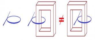
Cores made from W-shaped plates have the best distribution of magnetic flux. The ring shape of U-shaped components has great resistance.
To carry out the calculation, you need to indicate the shape of the core according to the type of plate (by clicking on the point) and its measured linear dimensions:
- The width of the plate under the coil with winding.
Thickness of the assembled package.
Paste this data into the appropriate table cells.
Step #2. Voltage selection
The transformer is created as a step-up, step-down (which is in principle reversible) or separating structure. In any case, you need to indicate what voltages you need on its primary and secondary windings in volts.
Fill in the indicated cells.
Step #3. AC signal frequency
By default, the standard household network value is set to 50 hertz. If necessary, it must be changed to that required by another calculation. But, this technique is not intended for high-frequency transformers used in switching power supplies.
They are created from other core materials and calculated in different ways.
Step #4. Efficiency
For conventional models of dry-type transformers, the efficiency depends on the applied electrical power and is calculated as an average value.
But, you can adjust its value manually.
Step #5. Magnetic inductance
The parameter determines the dependence of the magnetic flux on the geometric dimensions and shape of the conductor through which the current flows.
By default, the average parameter of 1.3 Tesla is adopted for calculating transformers. It can be adjusted.
Step #6. Current Density
The term is used to select the winding wire according to operating conditions. The average value for copper is 3.5 amperes per square millimeter of cross-section.
To operate the transformer in conditions of increased heating, it should be reduced. For forced cooling or reduced loads, it is permissible to increase. However, 3.5 A/mm kV is quite suitable for household devices.
Performing online transformer calculations
After filling in the cells with the original data, click on the “Calculate” button. The program automatically processes the entered data and displays the calculation results in a table.
How to calculate a power transformer using formulas in 5 steps
I present a simplified method that I have been using for several decades to create and test homemade transformer devices made from iron of an unknown brand in terms of load power.
Using it, I almost always managed to wind the circuit on the first try. Very rarely it was necessary to add or reduce a certain number of turns.
Stage No. 1. How does the power of a dry-type transformer affect the shape and cross-section of the magnetic circuit?
The calculation is based on the average efficiency ratio ŋ, as the ratio of the electrical power S2 converted in the secondary winding to the applied total power S1 in the primary.
Power losses in the secondary winding are estimated using a statistical table.
| Transformer power, watts | Efficiency ŋ |
| 15÷50 | 0,50÷0,80 |
| 50÷150 | 0,80÷0,90 |
| 150÷300 | 0,90÷0,93 |
| 300÷1000 | 0,93÷0,95 |
| >1000 | 0.95÷0,98 |
The electrical power of the device is determined by the product of the rated current flowing through the primary winding in amperes and the household wiring voltage in volts.
It is converted into magnetic energy flowing through the core, fully distributed in it depending on the shape of the flow distribution:
- for a ring figure of U-shaped plates, the cross-sectional area under the magnetic circuit coil is calculated as Qc=√S1;
- for a core made of Ш-shaped plates Qc=0.7√S1.
Stage No. 2. Features of calculating the transformation ratio and currents inside the windings
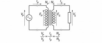
A power transformer is created to convert electrical energy from one voltage value to another, for example, U1=220 volts at the input and U2=24 V at the output.
The transformation ratio in the above example is written as the expression 220/24 or a fraction with the primary voltage value in the numerator and the secondary voltage in the denominator. It also allows you to determine the ratio of the number of turns between the windings.
At the first stage, we have already determined the electrical power of each winding. Using them and the voltage value, it is necessary to calculate the strength of the electric current I=S/U inside any coil.
Stage No. 3. How to calculate the diameters of copper wire for each winding
When determining the cross-section of the coil conductor, an empirical expression is used, taking into account that the current density lies in the range of 1.8÷3 amperes per square millimeter.
We determined the current value in amperes for each winding in the previous step.
Now we simply take the square root of it and multiply by a factor of 0.8. We write the resulting number in millimeters. This is the estimated wire diameter for the coil.
It is selected taking into account the release of permissible heat due to the current flowing through it. If space in the core window allows, the diameter can be slightly increased. Then these windings will be better adapted to thermal loads.
When, even with tight winding, all the turns of the wire do not fit into the window of the magnetic circuit, then its cross-section can be slightly reduced. But, such a transformer should be used for short-term operation and subsequent cooling.
Stage No. 4. Determining the number of turns of windings according to the characteristics of electrical steel: important points
The calculation is based on the magnetic properties of the iron core. Industrial transformers are assembled from different types of electrical steel, selected for specific operating conditions. They are calculated using complex, individual algorithms.
The home handyman gets magnetic cores of an unknown brand, the electrical characteristics of which are practically impossible for him to determine. Therefore, the formulas take into account average parameters, which are not difficult to adjust during setup.
For the calculation, an empirical coefficient ω' is introduced. It takes into account the magnitude of the voltage in volts, which is induced in one turn of the coil and is associated with the cross-section of the magnetic circuit Qc (cm kV).
In the primary winding, we calculate the number of turns as W1= ω'∙U1, and in the secondary - W2= ω'∙U2.
Stage No. 5. Taking into account the free space inside the magnetic circuit window
At this step, you need to estimate whether all the windings will fit into the free space of the core window, taking into account the dimensions of the coil.
To do this, we assume that the wire does not have a round cross-section, but a square with a side of the same diameter. Then, with absolutely ideal dense packing, it will occupy an area equal to the product of the unit section and the number of turns.
We increase this area by 30 percent, because it will not be possible to wind the turns perfectly this way. This will be a place inside the cavities of the coil, and it will still take up a certain space.
Next, we compare the resulting areas for the coils of each winding with the window of the magnetic circuit and draw conclusions.
The second way to evaluate is to wind the coils “for luck.” It can be used if the new design is rewound with wire from old working coils on the same core.
Typical parameter calculation
Quite often, radio amateurs use a simplified method when calculating a transformer. It allows you to perform calculations at home without using quantities that are difficult to know. But it’s easier to use an online calculator ready for calculating a transformer. In order to use such a calculator, you will need to know some data, namely:
- voltage of the primary and secondary windings;
- core dimensions;
- plate thickness.
After entering them, you will need to click the “Calculate” button or something similar in name and wait for the result.
Rod type magnetic core
If it is not possible to calculate on a calculator, performing such an operation yourself is not difficult and manually. To do this, you will need to determine the voltage at the output of the secondary winding U2 and the required power Po. The calculation proceeds as follows:
- The load current is calculated: In=Po/U2, A.
- The value of the secondary winding current is calculated: I2 = 1.5*In, A.
- The power of the secondary winding is determined: P2 = U2*I2, W.
- The total power of the device is found: Pt = 1.25*P2, W.
- The current strength of the primary winding is calculated: I1 = Pt/U1, A.
- The required cross-section of the magnetic circuit is found: S = 1.3*√ Pt, cm².
It should be noted that if a device is designed with several terminals in the secondary winding, then in the fourth point all powers are summed up and their result is substituted instead of P2.
After the first stage is completed, proceed to the next stage of calculation. The number of turns in the primary winding is determined by the formula: K1 = 50*U1/S. And the number of turns of the secondary winding is determined by the expression K2= 55* U2/S, where:
- U1 - voltage of the primary winding, V.
- S—core area, cm².
- K1, K2 - number of turns in windings, pcs.
It remains to calculate the diameter of the wound wire. It is equal to D = 0.632*√ I, where:
- d — wire diameter, mm.
- I is the winding current of the calculated coil, A.
When selecting a magnetic core, you should maintain a ratio of 1 to 2 of the width of the core to its thickness. At the end of the calculation, the fillability is checked, i.e. whether the winding will fit on the frame. To do this, the window area is calculated using the formula: So = 50*Pt, mm2.
Autotransformer Features
Autotransformers are calculated similarly to simple transformers, only the core is determined not for the entire power, but for the power of the voltage difference.
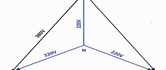
For example, the power of the magnetic circuit is 250 W, the input is 220 volts, and the output needs to be 240 volts. The voltage difference is 20 V, with a power of 250 W the current will be 12.5 A. This current value corresponds to a power of 12.5 * 240 = 3000 W. The mains current consumption is 12.5+250/220=13.64A, which exactly corresponds to 3000W=220V*13.64A. The transformer has one 240 V winding with a 220 V tap, which is connected to the network. The section between the outlet and the outlet is wound with a wire rated at 12.5A.
Thus, an autotransformer allows you to obtain significantly more output power than a transformer with the same core with a low transmission coefficient.
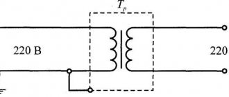
Toroidal type transformer
Toroidal transformers have a number of advantages over other types: smaller size, lighter weight and, at the same time, higher efficiency. At the same time, they are easily wound and rewound. Using an online calculator to calculate a toroidal transformer allows you not only to reduce the manufacturing time of the product, but also to experiment on the fly with different input data. The following data is used:
- input winding voltage, V;
- output winding voltage, V;
- output winding current, A;
- outer diameter of the torus, mm;
- internal diameter of the torus, mm;
- torus height, mm.
It should be noted that almost all online programs do not demonstrate particular accuracy when calculating pulse transformers. To obtain high accuracy, you can use specially developed programs, for example, Lite-CalcIT, or calculate manually. For independent calculations, use the following formulas:
- Output winding power: P2=I2*U2, W.
- Overall power: Pg=P2/Q, W. Where Q is the coefficient taken from the reference book (0.76−0.96).
- The actual cross-section of the “iron” at the location of the coil: Sch= ((Dd)*h)/2, mm2.
- Calculated cross-section of the “iron” at the location of the coil: Sw =√Pq/1.2, mm2
- Torus window area: Sfh=d*s* π/4, mm2.
- The value of the operating current of the input winding: I1=P2/(U1*Q*cosφ), A, where cosφ is a reference value (from 0.85 to 0.94).
- The wire cross-section is found separately for each winding from the expression: Sp = I/J, mm2., where J is the current density taken from the reference book (from 3 to 5).
- The number of turns in the windings is calculated separately for each coil: Wn=45*Un*(1-Y/100)/Bm* Sch pcs., where Y is a table value that depends on the total power of the output windings.
- It remains to find the output power and the calculation of the toroidal power transformer is considered completed. Pout = Bm*J*Kok*Kct* Sch* Sfh /0.901, where: Bm - magnetic induction, Kok - wire filling coefficient, Kct - iron filling coefficient.
All coefficient values are taken from the radio equipment reference book (REA). Thus, it is not difficult to carry out calculations manually, but you will need accuracy and access to reference data, so it is much easier to use online services.