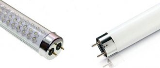
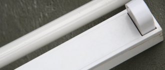
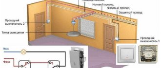
With rising electricity prices, we have to think about more economical lamps. Some of these use daylight lighting fixtures. The connection diagram for fluorescent lamps is not too complicated, so even without special knowledge of electrical engineering you can figure it out.
Good illumination and linear dimensions - the advantages of daylight
How to connect a lamp
A fluorescent lamp can be connected in several ways. The choice depends on the operating conditions and user preferences.
Connection using electromagnetic ballast
A common connection method is using a starter and electronic ballasts. The mains power starts the starter, which closes the bimetallic electrodes.
The current in the circuit is limited by an internal choke resistance. The operating current can be increased almost three times. The rapid heating of the electrodes and the appearance of the self-induction process cause ignition.
Connection using electronic ballasts
Comparing the method with other schemes for connecting fluorescent lamps, we can formulate the disadvantages:
- significant energy consumption;
- long startup, which can take 3 s;
- the circuit is not capable of functioning at low temperatures;
- unwanted stroboscopic blinking, which negatively affects vision;
- Throttle plates may make a humming noise as they wear out.
Two tubes and two chokes
In this case, a series connection of loads is implemented with a phase supplied to the resistance input.
The output is connected through the phase to the contact of the lighting device. The second contact is routed to the desired starter input.
Scheme with two tubes and two chokes
From the starter, the contact goes to the lamp, and the free pole goes to the zero of the circuit. A second lamp is also connected. The choke is connected, after which the bulb is mounted.
Connection diagram for two lamps from one choke
To connect two lighting fixtures from one stabilizer, you will need two starters. The circuit is economical, since the choke is the most expensive component of the system. The diagram is shown in the figure below.
Connection diagram for two lamps from one choke
Electronic ballast
Electronic ballast is a modern analogue of a traditional electromagnetic stabilizer. It significantly improves the startup of the circuit and makes using the lighting device more comfortable.
The current supplied to the load is rectified through a diode bridge. At the same time, the voltage is smoothed out, and the capacitors guarantee a stable supply of electricity.
Connection using electronic ballast
In this case, the transformer windings are turned on in antiphase, and the generator is loaded with high-frequency voltage. When a resonant voltage is applied inside the flask, a breakdown of the gaseous medium occurs, which generates the necessary glow.
Immediately after ignition, the resistance and voltage supplied to the load drop. Starting up using the circuit usually takes no more than a second. Moreover, you can easily use lighting sources without a starter.
Using Voltage Multipliers
Using Voltage Multipliers
The method helps to use a fluorescent lamp without electromagnetic balancing. In some cases, it is the most effective and extends the service life of the device. Even burnt-out devices can work for some time at powers not exceeding 40 W.
The rectification circuit provides significant acceleration and the ability to double the voltage. To stabilize it, capacitors are used.
It is important to remember that fluorescent light bulbs are not designed to operate with direct current. Over time, mercury accumulates in a certain area, reducing brightness. To restore the indicator, it is necessary to periodically change the polarity by turning the flask over
You can install a switch so you don’t have to disassemble the device
To restore the indicator, it is necessary to periodically change the polarity by turning the flask over. You can install a switch so as not to disassemble the device.
Connection without starter
Connection diagram without starter
The starter increases the heating time of the device. However, it is short-lived, so users are thinking about connecting lighting without it through secondary transformer windings.
Chokes and their purpose when using fluorescent lamps
A choke is a part used to regulate the current. This part separates or limits electrical signals of different frequencies and eliminates DC ripple.
Why and why is it needed in daylight devices?
Fluorescent lamps (daylight), as one of the types of discharge lamps, cannot be connected for lighting in the same way as a conventional heating electric lamp. To connect them, it is necessary to use an additional ballast.
The choke is switched on using a series connection with a fluorescent lamp and is designed to limit the current that flows through its electrodes. This device is characterized by the presence of reactance, as well as the absence of excessive heat generation. The choke can limit the current and prevent its avalanche-like growth when connected to the network.
The throttle is an integral part of any starter activation system. In addition, it is capable of performing the following additional functions:
- creating a safe current for a specific lamp, at which it is possible to ensure heating of its electrodes when ignited;
- the formation of an increased voltage pulse, which contributes to the occurrence of a discharge in the lamp bulb;
- ensuring stabilization of the electrical discharge;
- facilitating uninterrupted operation of the lamp during voltage fluctuations in the electrical network.
Specifications
The main technical characteristics of the part in question are power loss coefficient and inductance. To indicate this coefficient, the parameters of current, power and capacitance of the capacitor are indicated on the device.
Inductance is the inductive reactance that makes it possible to regulate the power of electricity supplied to the lamp contacts.
Kinds
Chokes are divided into the same types as the lamps connected to them. If you connect a lamp to a choke that does not meet its specifications, this will most likely lead to failure of any of the elements used in the connection system. There are the following types of chokes, divided depending on power:
- choke with a power of 9 W - for energy-saving lamps;
- 11 W - for miniature lamps;
- 15 W - for table lamps;
- 18 W - for office lamps;
- 36 W - for small fluorescent lamps;
- 58 W - for ceiling lamps;
- 65 W - for multi-lamp ceiling lamps;
- 80 W - for large fluorescent lamps.
Device
A typical connection diagram for a gas-discharge type choke is shown in the figure below.
Legend:
- EL - lamp;
- SF - starter;
- LL - throttle;
- 1, 2 — lamp spirals;
- C is a capacitor.
Operating principle of a fluorescent lamp
Fluorescent lamps take advantage of the ability of mercury vapor to emit infrared waves under the influence of electricity. This radiation is transferred into the range visible to our eyes by phosphor substances.
Therefore, an ordinary fluorescent lamp is a glass bulb, the walls of which are coated with a phosphor. There is also some mercury inside. There are two tungsten electrodes that provide electron emission and heating (evaporation) of mercury. The flask is filled with an inert gas, most often argon. The glow begins in the presence of mercury vapor heated to a certain temperature.
Basic design of a fluorescent fluorescent lamp
But normal network voltage is not enough to evaporate mercury. To begin work, start-up and control devices (abbreviated as ballasts) are turned on in parallel with the electrodes. Their task is to create a short-term voltage surge necessary to start the glow, and then limit the operating current, preventing its uncontrolled increase. These devices - ballasts - come in two types - electromagnetic and electronic. Accordingly, the schemes are different.
Checking functionality
If, after connecting, your lamp does not want to work or does not work correctly, you should check it and test it to make sure it is working properly. To do this, a special tester or ohmmeter will help you.
With their help, it is necessary to check all turns of the winding for breaks or short circuits between adjacent turns. If the circuit has an open circuit, then the resistance will be infinitely large and the meter will show an abnormal value. In this case, it is necessary to completely replace the winding.
If there is no break, but there is a loss of insulation due to which a short circuit occurs, the resistance will increase slightly. If a small number of turns interact with each other, then the increase will be insignificant.
If the short circuit occurs in the inductor winding, then there will be virtually no increase in resistance and this will not affect the operation of the device in any way. After checking the entire winding with an ohmmeter or tester and finding no problems, you need to look for the problem in the light bulb itself or in the power supply system.
We start the lamp without a choke
If you want to use the drl 250 model as a normal device without using a standard choke, it can be connected using special technology.
The simplest connection option is to purchase a special drl 250, which can work without a throttle. It is equipped with a special spiral that acts as a stabilizer and further dilutes the emitted light.
One option not to use a choke is to connect a regular incandescent lamp to the circuit. It must have the same power as the DRL in order to produce the necessary resistance and supply voltage to the DRL 250 light source.
Another option to remove the inductor from the structure is to install a capacitor or group of capacitors. But in this case, it is necessary to accurately calculate the current they produce. It must fully comply with the required voltage for operation.
Connection diagram via inductor
In order for the DRL lamp to work properly, the correct connection diagram for this device is necessary. Thanks to proper installation, lighting such a llama will not be any problem, and it will always work efficiently and without failures.
In addition, an incorrect connection increases the risk that the device will deteriorate and burn out ahead of time or at all, when first turned on.
The connection diagram is quite simple and represents a circuit of a series-connected inductor and the DRL 250 device itself. The connection is made to a 220 volt network and operates at a standard frequency. Therefore, they can be easily installed on a home network. The throttle works as a stabilizer and work corrector. Thanks to it, the light source does not flicker, operates continuously, and even with an unstable input voltage, the luminous flux remains unchanged.
Connecting DRL via throttle
A chokeless connection is not possible, as the lamp will burn out immediately. To start, the circuit must be supplied with a fairly high voltage, which sometimes reaches a level equivalent to two or three incoming voltages.
As previously mentioned, the drl device does not light up immediately. In rare cases, complete warm-up and start of operation at full power may take fifteen minutes.
Electronic ballast
All the shortcomings of the scheme described above stimulated research. As a result, an electronic ballast circuit was developed. It does not supply a network frequency of 50 Hz, but high-frequency oscillations (20-60 kHz), thereby eliminating the flickering of light, which is very unpleasant for the eyes.
One of the electronic ballasts is electronic ballasts
The electronic ballast looks like a small block with terminals removed. Inside there is one printed circuit board on which the entire circuit is assembled. The block has small dimensions and is mounted in the body of even the smallest lamp. The parameters are selected so that the start-up occurs quickly and silently. You don't need any more devices to work. This is the so-called starterless switching circuit.
Each device has a diagram on the back side. It immediately shows how many lamps are connected to it. The information is also duplicated in the inscriptions. The power of the lamps and their number, as well as the technical characteristics of the device are indicated. For example, the unit in the photo above can only serve one lamp. Its connection diagram is on the right. As you can see, there is nothing complicated. Take the wires and connect the conductors to the indicated contacts:
- Connect the first and second contacts of the block output to one pair of lamp contacts:
- serve the third and fourth to the other pair;
- supply power to the entrance.
All. The lamp is working. The circuit for connecting two fluorescent lamps to electronic ballasts is not much more complicated (see the circuit in the photo below).
Electronic ballasts for two fluorescent lamps
The advantages of electronic ballasts are described in the video.
The same device is built into the base of fluorescent lamps with standard sockets, which are also called “economy lamps”. This is a similar lighting device, only greatly modified.
These are also fluorescent lamps, only the shape is different.
Parameters and markings
When choosing a starting device, you need to pay special attention to its parameters and technical characteristics:
- Service life established by manufacturers. The leaders in this indicator are Osram and Phillips, whose products can withstand at least 6 thousand on and off cycles. However, in practice, this parameter is not always observed for objective reasons, for example, due to surges in mains voltage.
- Operating temperature range. Usually set within 5-55C. If you need to use luminaires outside the established standards, then for these cases you will need special starters with a much higher cost.
- The time period during which the cathodes are fully heated. This factor determines the period that the bimetallic electrodes are in the closed position. This indicator may vary significantly among different manufacturers.
- Varieties and modifications of capacitors involved in a particular device. The service life of the device largely depends on its design.
- Rated operating voltage. This characteristic must be checked, since a device designed for 127 V and connected to a 220 V lamp will immediately fail.
All parameters are displayed on the device label. For domestic devices it looks like this:
- The letter "C" indicates that it belongs to the starter category.
- The numbers in front of the letter “C” indicate the power of the lamp for which this starter is intended.
- The numbers behind the letter “C” correspond to the operating voltage parameters, for example, 127 or 220.
Types of starters
- Glow row starters are a lamp with bimetallic electrodes. Such starters are more often used because they have a simplified design and a relatively short ignition time.
- Thermal starters are characterized by an increased ignition time, due to which the electrodes heat up longer, which has a positive effect on the operation of the lamp. However, such starters have a more complex structure, additionally consume energy, and their connection diagram has a complex structure.
- Semiconductor starters. Their work is based on the key principle. After heating the electrodes, the voltage opens and a pulse occurs in the flask.
