Solar energy is so far limited (at the household level) to the creation of photovoltaic panels of relatively low power. But regardless of the design of the photoelectric converter of solar light into current, this device is equipped with a module called a solar battery charge controller.
Indeed, the solar photosynthesis installation includes a rechargeable battery - a storage device for the energy received from the solar panel. It is this secondary energy source that is primarily served by the controller.
In the article we present, we will understand the design and operating principles of this device, and also consider how to connect it.
Types used in practice
At the industrial level, two types of electronic devices have been launched and are being produced, the design of which is suitable for installation in a solar energy system:
- PWM series devices.
- MPPT series devices.
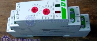
The first type of controller for a solar battery can be called “old man”. Such schemes were developed and put into operation at the dawn of the development of solar and wind energy.
The operating principle of the PWM controller circuit is based on pulse width modulation algorithms. The functionality of such devices is somewhat inferior to the more advanced devices of the MPPT series, but in general they also work quite effectively.
One of the popular solar station battery charge controller models in society, despite the fact that the device circuit is made using PWM technology, which is considered outdated
Designs using Maximum Power Point Tracking technology (tracking the maximum power limit) are distinguished by a modern approach to circuit solutions and provide greater functionality.
But if we compare both types of controller and, especially, with a bias towards the domestic sphere, MPPT devices do not look in the rosy light in which they are traditionally advertised.
MPPT type controller:
- has a higher cost;
- has a complex configuration algorithm;
- gives a gain in power only on panels of a large area.
This type of equipment is more suitable for global solar energy systems.
A controller designed for operation as part of a solar power installation. It is a representative of the class of MPPT devices - more advanced and efficient
For the needs of an ordinary user from a domestic environment, who, as a rule, has small-area panels, it is more profitable to buy and operate a PWM controller (PWM) with the same effect.
Types
On/Off
This type of device is considered the simplest and cheapest. Its only and main task is to turn off the charge supply to the battery when the maximum voltage is reached to prevent overheating.
However, this type has a certain disadvantage, which is that it switches off too early. After reaching the maximum current, you need to maintain the charging process for a couple more hours, and this controller will immediately turn it off.
As a result, the battery charge will be around 70% of the maximum. This has a negative impact on the battery.
PWM
This type is an improved On/Off. The modernization lies in the fact that it has a built-in pulse width modulation (PWM) system. This function allowed the controller, when the maximum voltage was reached, not to turn off the current supply, but to reduce its strength.
Because of this, it became possible to charge the device almost 100%.
MRRT
This type is considered the most advanced at present. The essence of its work is based on the fact that it is able to determine the exact value of the maximum voltage for a given battery. It continuously monitors the current and voltage in the system. Due to the constant acquisition of these parameters, the processor is able to maintain the most optimal current and voltage values, which allows it to create maximum power.
If we compare the MPPT and PWN controllers, the efficiency of the former is approximately 20-35% higher.
Block diagrams of controllers
Schematic diagrams of PWM and MPPT controllers to consider them with a layman's eye are too complex a point associated with a subtle understanding of electronics. Therefore, it is logical to consider only structural diagrams. This approach is understandable to a wide range of people.
Option #1 - PWM devices
The voltage from the solar panel travels through two conductors (positive and negative) to the stabilizing element and the separating resistive circuit. Due to this piece of the circuit, potential equalization of the input voltage is obtained and, to some extent, they organize protection of the controller input from exceeding the input voltage limit.
It should be emphasized here: each individual device model has a specific input voltage limit (indicated in the documentation).
This is approximately what the block diagram of devices made on the basis of PWM technologies looks like. For operation as part of small household stations, this circuit approach provides quite sufficient efficiency
Next, the voltage and current are limited to the required value by power transistors. These circuit components are in turn controlled by the controller chip through the driver chip. As a result, the output of a pair of power transistors sets the normal value of voltage and current for the battery.
The circuit also contains a temperature sensor and a driver that controls the power transistor, which regulates the load power (protection against deep discharge of the battery). The temperature sensor monitors the heating status of important elements of the PWM controller.
Usually the temperature level inside the case or on the heatsinks of power transistors. If the temperature goes beyond the limits set in the settings, the device turns off all active power lines.
Option #2 - MPPT devices
The complexity of the circuit in this case is due to its addition to a number of elements that build the necessary control algorithm more carefully, based on operating conditions.
Voltage and current levels are monitored and compared by comparator circuits, and based on the comparison results, the maximum output power is determined.
Circuit design in structural form for charge controllers based on MPPT technologies. A more complex algorithm for monitoring and controlling peripheral devices is already noted here.
The main difference between this type of controller and PWM devices is that they are able to adjust the solar energy module to maximum power, regardless of weather conditions.
The circuitry of such devices implements several control methods:
- disturbances and observations;
- increasing conductivity;
- current sweep;
- constant voltage.
And in the final segment of the overall action, an algorithm for comparing all these methods is also used.
Battery selection
When choosing batteries for solar panels, FORUMHOUSE users are guided by different considerations:
- Those who have the means and capabilities purchase durable and expensive alkaline batteries - nickel-cadmium (NC) or nickel-iron (NI).
- Some people purchase specialized gel batteries made using GEL technology, which last much longer than conventional starter batteries, but are also more expensive.
- Those who prefer the most affordable option use starter car batteries.
Considering that the choice of battery largely depends on the actual capabilities of the owner of the battery, it is very difficult to give any recommendations in this regard. But the advantages and disadvantages of various batteries should be listed.
Acid (car) batteries
Starter batteries are the cheapest and most affordable batteries for most buyers. Despite the rather impressive capacity, these batteries are buffer batteries: they are initially designed for short-term shallow discharge and quick recharging to full capacity. They are absolutely not designed to work in cyclic mode and deep discharge conditions. This leads to the disadvantages of the presented batteries.
vvaleryvv FORUMHOUSE user, Moscow.
Car batteries have a buffer mode of operation! Therefore, in a battery with a cyclic operating mode (it doesn’t matter whether there is a 3-stage charging or not), the maximum is a year of operation, and the starter battery is used. I am basing this on the experience of a very large eco-village that does not have a power grid. More than a hundred families have tried lead batteries (naturally, starting with the starter). The result is always the same: with constant use the battery lasts for a year, with seasonal use it can last 2-3 years.
In order to bring the service life of a car battery closer to its maximum, it is necessary to create conditions under which its discharge will not exceed 20-30% of the rated capacity. At the same time, ensure immediate recharging of the battery. It is quite difficult to implement such a cycle in autonomous power supply systems, so in practice the battery is discharged by no more than 50%. You cannot discharge the battery by more than 80%, because... This very quickly leads to battery failure.
The table shows the dependence of the open circuit voltage on the degree of discharge of the lead-acid battery.
The table gives an approximate understanding of the voltage value at which the load from the battery should be disconnected (cut-off voltage). It is approximate because the voltage of the battery connected to the load is always lower than the open circuit voltage of the battery. Idle parameters are measured several hours after the load is turned off. When setting the cut-off voltage, it is better to follow the recommendations of the battery manufacturers and the controller readings (most devices show the percentage of battery charge).
Chernomor93FORUMHOUSE user
Look at the passport for your battery. Yesterday I looked at information about what currents can be used to discharge it and to what values.
Alkaline batteries
Alkaline batteries are designed for cyclic operation (which is optimal for autonomous power supply systems): they are able to gradually release their energy until they are completely discharged.
And the deeper such a battery is discharged, the more capacity it will gain during recharging (this is called the memory effect).
Leo2FORUMHOUSE user
You cannot charge and discharge an alkaline battery in portions - only “from start to finish”. But with proper use (in addition to charging/discharging, it involves washing the cans and replacing the electrolyte once a season), alkaline batteries last for 20 years.
A significant disadvantage of alkaline batteries is that at low currents they charge poorly or do not charge at all. This problem can be solved by correctly calculating the power of solar panels and installing a suitable controller.
Conclusion: if possible, then it is better to purchase alkaline batteries for solar panels.
WatchCatFORUMHOUSE user
We have a village here for a quarter of a century without a centralized power supply, and all residents use 12 V batteries. Moreover, by hook or by crook, they have always mined alkaline ones (NK and NL). I currently have ten cans of TNZh-250 from a loader working, written off in the early 90s. They contain about a third of the passport capacity, but this is quite enough for me, and this capacity has not changed for many years.
Gel batteries
If the disadvantages of car batteries are unacceptable to the consumer, and he does not have the opportunity to purchase a suitable alkaline battery, then the choice is made in favor of lead-acid gel batteries. According to their characteristics, they are optimally suited for autonomous solar and wind energy systems, do not require maintenance, and their service life is 10 years. The disadvantage of gel batteries is their high cost.
There are also lithium iron phosphate batteries (lithium ion). By the way, they are recognized as the best batteries for autonomous systems.
Taking into account the “exorbitant cost of these devices, only a few are used in homemade systems.
Controller connection methods
Considering the topic of connections, it should immediately be noted: for the installation of each individual device, a characteristic feature is working with a specific series of solar panels.
So, for example, if a controller is used that is designed for a maximum input voltage of 100 volts, a series of solar panels should output a voltage no greater than this value.
Any solar power installation operates according to the rule of balancing the output and input voltages of the first stage. The upper limit of the controller voltage must correspond to the upper limit of the panel voltage
Before connecting the device, you need to decide on the location of its physical installation. According to the rules, the installation location should be chosen in dry, well-ventilated areas. Avoid the presence of flammable materials near the device.
The presence of sources of vibration, heat and humidity in the immediate vicinity of the device is unacceptable. The installation site must be protected from precipitation and direct sunlight.
Connection technology for PWM models
Almost all manufacturers of PWM controllers require that the devices be connected in the exact sequence.
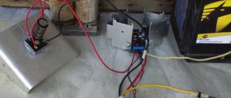
The technique of connecting PWM controllers to peripheral devices is not particularly difficult. Each board is equipped with labeled terminals. Here you simply need to follow the sequence of actions
Peripheral devices must be connected in full accordance with the designations of the contact terminals:
- Connect the battery wires to the battery terminals of the device in accordance with the indicated polarity.
- Switch on the protective fuse directly at the point of contact of the positive wire.
- Attach the conductors coming from the solar panel battery to the controller contacts intended for the solar panel. Observe polarity.
- Connect a test lamp of the appropriate voltage (usually 12/24V) to the load terminals of the device.
The specified sequence must not be violated. For example, connecting solar panels first when the battery is not connected is strictly prohibited. By doing this, the user runs the risk of “burning” the device. This material describes in more detail the assembly diagram of solar panels with a battery.
Also, for PWM series controllers, it is not permissible to connect a voltage inverter to the controller load terminals. The inverter should be connected directly to the battery terminals.
Procedure for connecting MPPT devices
The general physical installation requirements for this type of device do not differ from previous systems. But the technological setup is often somewhat different, since MPPT controllers are often considered more powerful devices.
For controllers designed for high power levels, it is recommended to use large cross-section cables equipped with metal end caps for power circuit connections.
For example, for powerful systems, these requirements are supplemented by the fact that manufacturers recommend using a cable for power connection lines designed for a current density of at least 4 A/mm2. That is, for example, for a controller with a current of 60 A, you need a cable to connect to the battery with a cross-section of at least 20 mm2.
Connecting cables must be equipped with copper lugs, tightly crimped with a special tool. The negative terminals of the solar panel and battery must be equipped with adapters with fuses and switches.
This approach eliminates energy losses and ensures safe operation of the installation.
Block diagram of connecting a powerful MPPT controller: 1 – solar panel; 2 – MPPT controller; 3 – terminal block; 4.5 – fuses; 6 – controller power switch; 7.8 – earth bus
Before connecting solar panels to the device, you should make sure that the voltage at the terminals is equal to or less than the voltage that can be supplied to the controller input.
Connecting peripherals to the MTTP device:
- Switch the panel and battery switches to the “off” position.
- Remove the protective fuses on the panel and battery.
- Connect the battery terminals with a cable to the controller terminals for the battery.
- Connect the terminals of the solar panel with a cable to the controller terminals indicated by the corresponding sign.
- Connect the ground terminal to the ground bus with a cable.
- Install the temperature sensor on the controller according to the instructions.
After these steps, you need to reinsert the previously removed battery fuse and turn the switch to the “on” position. A battery detection signal will appear on the controller screen.
Next, after a short pause (1-2 minutes), replace the previously removed solar panel fuse and turn the panel switch to the “on” position.
The device screen will show the voltage value of the solar panel. This moment indicates the successful launch of the solar energy installation.
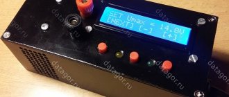
Principle of operation
If there is no current from the solar battery, the controller is in sleep mode. It doesn't use a single watt from the battery. After sunlight hits the panel, electric current begins to flow to the controller. It should turn on. However, the indicator LED along with 2 weak transistors turns on only when the current voltage reaches 10 V.
Once this voltage is reached, current will flow through the Schottky diode to the battery. If the voltage rises to 14 V, amplifier U1 will start working, which will open the MOSFET transistor. As a result, the LED will go out and two low-power transistors will close. The battery will not charge. At this time, C2 will be discharged. On average this takes 3 seconds. After capacitor C2 discharges, the hysteresis of U1 will be overcome, the MOSFET will close, and the battery will begin to charge. Charging will continue until the voltage rises to the switching level.
Charging occurs periodically. Moreover, its duration depends on the charging current of the battery and how powerful the devices connected to it are. Charging continues until the voltage reaches 14 V.
The circuit turns on in a very short time. Its activation is influenced by the charging time of C2 with current, which limits transistor Q3. The current cannot be more than 40 mA.
Conclusions and useful video on the topic
The industry produces devices that are multifaceted in terms of circuit designs. Therefore, it is impossible to give unambiguous recommendations regarding the connection of all installations without exception.
However, the main principle for any type of device remains the same: without connecting the battery to the controller buses, connection to photovoltaic panels is unacceptable. Similar requirements apply for inclusion in a voltage inverter circuit. It should be considered as a separate module connected to the battery via direct contact.
If you have the necessary experience or knowledge, please share it with our readers. Leave your comments in the block below. Here you can also read about the topic of the article.
How can some components be replaced?
Any of these elements can be replaced. When installing other circuits, you need to think about changing the capacitance of capacitor C2 and selecting the bias of transistor Q3.
Instead of a MOSFET transistor, you can install any other one. The element must have low open channel resistance. It is better not to replace the Schottky diode. You can install a regular diode, but it must be placed correctly.
Resistors R8, R10 are equal to 92 kOhm. This value is non-standard. Because of this, such resistors are difficult to find. Their full replacement can be two resistors with 82 and 10 kOhm. They must be turned on sequentially.
If the controller will not be used in an aggressive environment, you can install a trimming resistor. It allows you to control the voltage. It will not work for long in an aggressive environment.
If you need to use a controller for more powerful panels, you need to replace the MOSFET transistor and diode with more powerful analogues. All other components do not need to be changed. There is no point in installing a heatsink to regulate 4A. By installing a MOSFET on a suitable heatsink, the device will be able to work with a more efficient panel.
Which is better to choose?
The choice of controller type is made based on the power and performance of the system . If they are small, you can limit yourself to installing a PWM controller. It's cheaper and easier.
However, if the kit produces significant power and supplies power to sensitive consumer devices, the best solution would be to use an MPPT controller. It is much more expensive, but is capable of setting up the most efficient operation of a set of equipment. In any case, the final choice is determined by the capabilities of the owner and the features of the existing solar complex.