I made this charger to charge car batteries, the output voltage is 14.5 volts, the maximum charge current is 6 A. But it can also charge other batteries, for example lithium-ion ones, since the output voltage and output current can be adjusted within a wide range. The main components of the charger were purchased on the AliExpress website.
These are the components:
You will also need an electrolytic capacitor 2200 uF at 50 V, a transformer for the TS-180-2 charger (see this article for how to solder the TS-180-2 transformer), wires, a power plug, fuses, a radiator for the diode bridge, crocodiles. You can use another transformer with a power of at least 150 W (for a charging current of 6 A), the secondary winding must be designed for a current of 10 A and produce a voltage of 15 - 20 volts. The diode bridge can be assembled from individual diodes designed for a current of at least 10A, for example D242A.
The wires in the charger should be thick and short. The diode bridge must be mounted on a large radiator. It is necessary to increase the radiators of the DC-DC converter, or use a fan for cooling.
Charger assembly
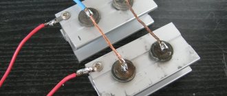
Connect a cord with a power plug and a fuse to the primary winding of the TS-180-2 transformer, install the diode bridge on the radiator, connect the diode bridge and the secondary winding of the transformer. Solder the capacitor to the positive and negative terminals of the diode bridge.
Connect the transformer to a 220 volt network and measure the voltages with a multimeter. I got the following results:
- The alternating voltage at the terminals of the secondary winding is 14.3 volts (mains voltage 228 volts).
- The constant voltage after the diode bridge and capacitor is 18.4 volts (no load).
Using the diagram as a guide, connect a step-down converter and a voltammeter to the DC-DC diode bridge.
How to calculate and select a diode bridge based on power
The maximum ripple voltage present in the full-wave rectifier circuit is determined not only by the value of the smoothing capacitor, but also by the frequency and load current and is calculated as:
Rectifier Bridge Ripple Voltage
Ripple Voltage Formula
Where: I is the DC load current in amperes, ƒ is the ripple frequency or twice the input frequency in Hertz, and C is the capacitance in Farads.
The main advantages of a full-wave bridge rectifier are that it has lower AC ripple for a given load and a smaller reservoir or smoothing capacitor than an equivalent half-wave rectifier. Therefore, the fundamental frequency of the ripple voltage is twice the AC frequency (100 Hz), where for a half-wave rectifier it is exactly equal to the supply frequency (50 Hz).
The amount of ripple voltage that is superimposed on top of the DC supply voltage by the diodes can be virtually eliminated by adding a greatly improved π filter (pi filter) to the output terminals of the bridge rectifier. This type of low-pass filter consists of two smoothing capacitors, usually of the same value, and an inductor or inductor across them to introduce a high-impedance path into the variable ripple component.
Bridge rectifier
Another, more practical and cheaper alternative is to use an off-the-shelf three-pole voltage regulator IC such as the LM78xx (where xx denotes the rated output voltage) for positive output voltage, or its inverse equivalent, LM79xx for negative output voltage, which can reduce ripple by more than 70 dB (datasheet), providing a continuous output current of more than 1 amp.
Many circuits with this technology are built with a bridge rectifier. Bridge rectifiers convert AC to DC using their diode system made of semiconductor material, either in a half-wave method, which rectifies one direction of the AC signal, or in a full-wave method, which rectifies both directions of the AC input signal.
Diode bridge GBL10
Semiconductors are materials that allow current to pass because they are made of metals such as gallium or metalloids such as silicon that are contaminated with materials such as phosphorus as a means of controlling the current. You can use a bridge rectifier for a variety of applications for a wide range of currents.
Bridge rectifiers also have the advantage of delivering more voltage and power than other rectifiers. Despite these advantages, bridge rectifiers suffer from the need to use four diodes with additional diodes compared to other rectifiers, causing a voltage drop that reduces the output voltage.
Setting the output voltage and charging current
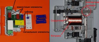
There are two trimming resistors installed on the DC-DC converter board, one allows you to set the maximum output voltage, the other allows you to set the maximum charging current.
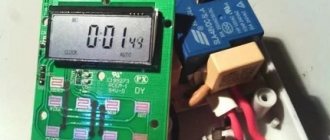
Plug in the charger (nothing is connected to the output wires), the indicator will show the voltage at the device output and the current is zero. Use the voltage potentiometer to set the output to 5 volts. Close the output wires together, use the current potentiometer to set the short circuit current to 6 A. Then eliminate the short circuit by disconnecting the output wires and use the voltage potentiometer to set the output to 14.5 volts.
Literature
M. Salato, A. Lokhandwala, M. Soldano. International Rectifier. AN-1087 Building a Secondary Arm Rectifier Using the IR1167 SmartRectifierTM Control IC
International Rectifier. Data Sheet of IR1167S Smart Rectifier Control IC
Adnaan Lokhandwala, Maurizio Salato, Marco Soldano. Portable Power Developers Conference 2006 New Output Rectification Control IC Improves Efficiency and Thermal Performance of External AC-DC Power Converters
US Patent Application No. 2005/0122753 A1 dated June 9, 2005
ATTENTION READERS!
There was a typo in the 11th issue of the magazine for 2009 on page 29.
Table name 2 should read: “Characteristics of switches.”
The first paragraph on the page should read:
“Texas Instruments offers fairly balanced solutions for video applications. The balance lies in the optimal, often interdependent, technical characteristics of the keys. For example, with a sufficiently low on-resistance, very high switching speeds are also achieved.”
•••
Reverse polarity protection
This charger is not afraid of a short circuit at the output, but if the polarity is reversed, it may fail. To protect against polarity reversal, a powerful Schottky diode can be installed in the gap in the positive wire going to the battery. Such diodes have a low voltage drop when connected directly. With such protection, if the polarity is reversed when connecting the battery, no current will flow. True, this diode will need to be installed on a radiator, since a large current will flow through it during charging.
Suitable diode assemblies are used in computer power supplies. This assembly contains two Schottky diodes with a common cathode; they will need to be paralleled. For our charger, diodes with a current of at least 15 A are suitable.
It must be taken into account that in such assemblies the cathode is connected to the housing, so these diodes must be installed on the radiator through an insulating gasket.
It is necessary to adjust the upper voltage limit again, taking into account the voltage drop across the protection diodes. To do this, use the voltage potentiometer on the DC-DC converter board to set 14.5 volts measured with a multimeter directly at the output terminals of the charger.
Electricity rectification
Until the end of the 19th century, converting alternating voltage to direct voltage was a problem. With the invention of the diode - first vacuum, and later semiconductor - the situation changed radically. Thanks to its unique properties, the diode perfectly distinguishes polarity and makes it easy to sort currents in the desired direction. At first, separate diodes were used for these purposes, later diode bridges appeared, providing high quality rectification.
https://youtube.com/watch?v=XamfUIu4wDI
Single diode rectifier
A diode conducts current in only one direction, which is why it is called a semiconductor device. If you connect the plus of the voltage source to the cathode of the device, and the minus to the anode, the diode will behave like a regular conductor. If the polarity is changed, the device will close and turn into a dielectric. To answer the question of what this gives, you will have to assemble a simple circuit and again arm yourself with an oscilloscope.
The diagram shows the operation of a semiconductor diode in an alternating current circuit. The oscillogram on the left shows the picture at the output of the transformer - ordinary alternating current. After the diode, everything changes significantly - the negative half-wave of the alternating voltage disappears from the graph. The current has not yet become constant, but it is no longer alternating - there is no movement of the electric charge in the opposite direction. This type of current is usually called pulsating. They can't power electronics yet, but changes are evident. All that remains is to smooth out the pulse peaks. This is done using capacitors.
The diagram shows a half-wave rectifier with a smoothing capacitor. During a positive pulse, the voltage not only powers the load, but also charges the capacitor at the same time. When the pulse ends, the capacitor releases the accumulated energy, smoothing out voltage surges.
Full wave device
Despite the significant progress achieved in converting alternating current into direct current by previous experiments, the result is still far from ideal. The fact is that the frequency of alternating current is quite low (50 Hz), and hanging smoothing capacitors has its limitations. In order to significantly improve the shape of the output signal, you need to increase the frequency.
However, in sockets it is strictly fixed and does not depend on external factors. The negative half-wave of the voltage is cut off by a diode. Changing its polarity is not difficult at all - you just need to add a few diodes to assemble a bridge circuit. The figure shows a full-wave rectifier with four diodes, explaining how a diode bridge works:
When a positive half-wave appears, diodes VD2, VD3 will be turned on in the forward direction and will be open. VD1, VD2 - closed. The half-wave passes freely to the output of the rectifier. When the voltage changes polarity, the pairs of diodes will change places - VD1 and VD4 will open, VD2 and VD3 will close. The negative half-wave will also pass to the output, but will change polarity. The result will be the same pulsed unipolar voltage, but its frequency will double. All that remains is to add a smoothing capacitor and see what happens.
The full-wave rectifier with a smoothing capacitor in the image shows that the problem has been solved: the alternating voltage is converted to direct voltage. Of course, the consistency is not ideal - there are pulsations, but they can be dealt with using filters. In addition, any electronics allows for one or another amount of pulsation.
This circuit, consisting of four diodes, has become classic and is called a diode or rectifier bridge. There is a separate category of electronic devices - rectifier bridges. They consist of four diodes connected to each other in a suitable manner. As an example, you can look at the rectifier bridge KTS402G and its electrical circuit.
How to charge the battery
Wipe the battery with a cloth soaked in soda solution, then dry. Remove the plugs and check the electrolyte level; if necessary, add distilled water. The plugs must be turned out during charging. No debris or dirt should get inside the battery. The room in which the battery is charged must be well ventilated.
Connect the battery to the charger and plug in the device. During charging, the voltage will gradually increase to 14.5 volts, the current will decrease over time. The battery can be conditionally considered charged when the charging current drops to 0.6 - 0.7 A.
Device diagram
All motorists have found themselves in such an unpleasant situation. There are two options: start the car with a charged battery from a neighbor’s car (if the neighbor doesn’t mind), in the jargon of car enthusiasts this sounds like “lighting a cigarette.” Well, the second way out is to charge the battery.
Instructions for verification
In answer to the question of how to check a diode with a multimeter without desoldering, it is necessary to clarify that in order to successfully test it, like a zener diode, you need to take it and a multimeter and make a test. As a rule, many of the devices are equipped with a diode test function. According to the instructions, it looks like this:
Anode and cathode
- All you need to do is set the regulator to the test function, take the ends of the multimeter and connect them to the diode assembly. You need to bring the anode to the minus sign, and the cathode to the plus sign. Often these are simply white and red stripes, respectively.
- Then the threshold voltage values and the value from the test readings will appear.
Connecting the anode and cathode
Note! When checking a Schottky or Schottky rectifier LED, you cannot touch one of the charges with your hands, since the readings in this case will not be correct. During the first determination, you need to repeat the procedure in the opposite order
So, the anode must be placed to the plus sign, and the cathode to the minus sign. With this connection, the multimeter will receive the number 1. This means that no current is flowing. Everything is protected.
It is worth noting that more detailed instructions with diagrams, answers to popular questions about LED narrow suppressors and warnings are given in the instructions for each multimeter.
Multimeter for checking the diode assembly
Checking the serviceability of semiconductor elements
To check semiconductor elements for serviceability, you need to use a digital measuring multimeter with a lid and great functionality. Most of them are equipped with a similar function for ringing the bridge and generator, so anyone can do the verification procedure. All you need to do is ring the free diode using a multifunctional multimeter, install the control knob on the measuring device and press the button with this designation on the control panel. Next, you need to connect the corresponding red probe to the anode, and the black one to the cathode. This is the only way the device will measure everything correctly.
Note! It is easy to understand where the anode is and where the cathode is by reading the description of the multimeter model, or using the help of an electronics engineer. As a rule, each wiring has its own marking, thanks to which it is very easy to understand where everything is in a particular situation.
The result should be a threshold forward voltage. If there is damage to any element, then a zero will appear on the panel opposite the electrode that will be connected, or a number higher or lower than the permissible one.
In response to how to check a diode assembly with a multimeter, if there is no special mode in the multimeter, you can indicate that it is necessary to assemble a circuit: connect the power source to a resistor and the semiconductor being tested. Then connect the anode element to the resistor, and the cathode to the power source. Next, you should press start and see what state the semiconductor element is in. As in the previous case, a working element will produce a direct voltage with the meter.
Checking with a multimeter without soldering
Without desoldering, you can check the electrodes with a multimeter. All you need to do is select the resistive measuring mode on the device with a range of 2 kOhm. Then, as standard, you need to connect the red wire to the anode part, and the black wire to the cathode part. This will show the voltage in ohms. As a rule, when the circuit is broken, the measurement is obtained with a figure higher than the permissible value or with a value of 0.
Note! It is important to understand that in order to test equipment and semiconductor elements, you must fully act in accordance with the instructions provided with the multimeter. It is also necessary to understand important physics and understand a little electronics to draw up a proper electrical diagram. Otherwise, lack of knowledge may make it difficult to operate the multimeter
Otherwise, lack of knowledge may make it difficult to operate the multimeter.
Correct connection of the electrodes is the key to a successful test
Answers to 5 Frequently Asked Questions
- Will I need to take any additional measures before charging the battery in my car?
– Yes, you will need to clean the terminals, since acid deposits appear on them during operation. The contacts need to be cleaned very well so that current flows to the battery without difficulty. Sometimes motorists use grease to treat terminals; this should also be removed. - How to wipe charger terminals?
— You can buy a specialized product in a store or prepare it yourself. Water and soda are used as a self-made solution. The components are mixed and stirred. This is an excellent option for treating all surfaces. When the acid comes into contact with soda, a reaction will occur and the motorist will definitely notice it. This area will need to be thoroughly wiped to get rid of all the acid. If the terminals were previously treated with grease, it can be removed with any clean rag. - If there are covers on the battery, do they need to be opened before charging?
— If there are covers on the body, they must be removed. - Why is it necessary to unscrew the battery caps?
— This is necessary so that the gases formed during the charging process can freely exit the case. - Is there a need to pay attention to the electrolyte level in the battery?
- This is done without fail. If the level is below the required level, then you need to add distilled water inside the battery. Determining the level is not difficult - the plates must be completely covered with liquid.
Physical properties of pn junction
The main element used to create a rectifier unit is a diode. Its operation is based on the electron-hole transition (pn).
The generally accepted definition says: a pn junction is a region of space located at the boundary of the junction of two semiconductors of different types. In this space, an n-type to p-type transition is formed. The value of conductivity depends on the atomic structure of the material, namely on how tightly the atoms hold electrons. Atoms in semiconductors are arranged in a lattice, and electrons are bound to them by electrochemical forces. This material itself is a dielectric. It either conducts current poorly or does not conduct it at all. But if atoms of certain elements are added to the lattice (doping), the physical properties of such a material change radically.
An excess charge of one sign causes carriers to repel each other, while an area with an opposite charge tends to attract them towards itself. An electron, moving, occupies a free space, a hole. At the same time, a hole also forms in its old place. As a result, two flows of charge movement are created: one main and the other reverse. A material with a negative charge uses electrons as majority carriers and is called an n-type semiconductor, while a material with a positive charge using holes is called a p-type semiconductor. In both types of semiconductors, minority charges generate a current opposite to the movement of the main charges.
In radio electronics, germanium and silicon are used from materials to create pn junctions. When crystals of these substances are doped, a semiconductor with different conductivity is formed. For example, the introduction of boron leads to the appearance of free holes and the formation of p-type conductivity. Adding phosphorus, on the other hand, will create electrons and the semiconductor will become n-type.
It’s also important to know: 3 nuances about operation
The homemade product differs somewhat in its method of operation from the factory version. This is explained by the fact that the purchased unit has built-in functions that help with operation. They are difficult to install on a device assembled at home, and therefore you will have to adhere to several rules during operation.
- A self-assembled charger will not turn off when the battery is fully charged. That is why it is necessary to periodically monitor the equipment and connect a multimeter to it to monitor the charge.
- You need to be very careful not to confuse “plus” and “minus”, otherwise the charger will burn out.
- The equipment must be turned off when connecting to the charger.
By following these simple rules, you will be able to properly recharge the battery and avoid unpleasant consequences.
Principle of operation
It is not difficult to understand the principle of operation of a semiconductor diode. All you need is to understand the basic laws of physics and know how some electrical processes occur.
Initially, an electric current acts on the cathode, which causes the heating element to glow. In turn, electrons are emitted from the electrode, and an electric field appears between the two parts.
The formation of a spatially negative charge begins in the two electrodes, which can impede the flow of electrons. However, this only happens when the anode potential decreases, as a result of which the mass of electrons is not able to cope with the negative elements, which forces them to move in the reverse order, that is, the electrons return to the cathode again.
Often the cathode current readings remain zero - this happens when exposed to particles with a minus charge. As a result, the generated field does not force the electrons to move faster, but causes the opposite reaction - it slows them down and forces them to return back to the cathode. Eventually the circuit opens as the diode remains in the off state.
How to avoid 2 mistakes when charging a battery
It is necessary to follow basic rules in order to properly charge the battery in your car.
- It is prohibited to connect the battery directly to the mains. Chargers are intended for this purpose.
- Even if the device is made with high quality and from good materials, you will still need to periodically monitor the charging process to avoid troubles.
Following simple rules will ensure reliable operation of self-made equipment. It is much easier to monitor the unit than to spend money on components for repairs.
The simplest battery charger
Scheme of a 100% working 12 volt charger
Look in the picture at the diagram of a 12 V charger. The equipment is intended for charging car batteries with a voltage of 14.5 Volts. The maximum current received during charging is 6 A. But the device is also suitable for other batteries - lithium-ion, since the voltage and output current can be adjusted. All the main components for assembling the device can be found on the Aliexpress website.
- dc-dc buck converter.
- Ammeter.
- Diode bridge KVRS 5010.
- Hubs 2200 uF at 50 volts.
- transformer TS 180-2.
- Circuit breakers.
- Plug for connecting to the network.
- "Crocodiles" for connecting terminals.
- Radiator for diode bridge.
Any transformer can be used at your own discretion. The main thing is that its power is not lower than 150 W (with a charging current of 6 A). It is necessary to install thick and short wires on the equipment. The diode bridge is fixed on a large radiator.
What are diodes
A diode is a semiconductor element based on a silicon crystal. Previously, these parts were also made of germanium, but over time this material was forced out due to its shortcomings. The electrical diode functions as a valve, i.e. it allows current to flow in one direction and blocks it in the other. Such capabilities are built into this part at the level of the atomic structure of its semiconductor crystals.
One diode cannot obtain a full constant voltage from an alternating voltage. Therefore, in practice, more complex combinations of these elements are used. An assembly of 4 or 6 parts, combined according to a special circuit, forms a diode bridge. He is already quite capable of coping with full current rectification.
Interesting. Diodes have parasitic sensitivity to temperature and light. Transparent rectifiers in a glass case can be used as light sensors. Germanium diodes (approx. D9B) are suitable as a temperature-sensitive element. Actually, due to the strong dependence of the properties of these elements on temperature, they stopped producing them.
Memory circuit for Rassvet 2
Look in the picture at the diagram of the Rassvet 2 charger. It is compiled according to the original charger. If you master this scheme, you will be able to independently create a high-quality copy that is no different from the original sample. Structurally, the device is a separate unit, closed with a housing to protect the electronics from moisture and exposure to bad weather conditions. It is necessary to connect a transformer and thyristors on the radiators to the base of the case. You will need a board that will stabilize the current charge and control the thyristors and terminals.