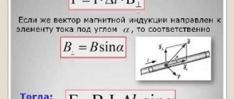
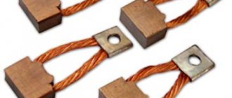
Just as a stationary electric charge acts on another charge through an electric field, an electric current acts on another current through a magnetic field. The effect of a magnetic field on permanent magnets is reduced to its effect on charges moving in the atoms of a substance and creating microscopic circular currents.
What is an electric field?
In physics, this concept is usually understood as a vector field that is formed around particles or bodies with a certain charge. The electric field is considered one of the two integral components of the electromagnetic field.
To better understand the nature of this phenomenon, you need to remember what the Coulomb force is. Coulomb's law serves to determine the degree of interaction between each of a pair of point electric charges. At the same time, it takes into account information about the interval between them.
To understand the tension of the phenomenon, it is worth turning to this example:
- There are 2 bodies that have a charge. In this case, one of them is stationary, and the second moves around the first.
- The Coulomb force in this case is equal to the product of charge and voltage.
- The tension will include the central charge parameter and the square of the distance from the center to the second body.
It is noteworthy that for each point of the electric field the Coulomb force parameter and direction will be different. Due to the difference in directions at different points, the concept is considered vector.
What is a magnetic field?
In physics, this term is understood as a force field that affects exclusively moving bodies, particles or charges.
Each element is characterized by a magnetic moment. The force in this case depends less on the movement of the charge. In this case, electrons act as charged particles. As for the strength of this type of field, the value will be in direct proportion to the speed of the charge and its parameters. The best example is planet Earth. Its central part consists of red-hot iron. Like other metal objects, it can move electrons around it. That is why the largest magnetic field on Earth is formed by the planet itself, or its center, to be more precise. If this field disappears, there is a high probability of disasters and even the death of living organisms.
Expert opinion Ekaterina Vladimirovna Karnaukh Graduated from the National University of Shipbuilding, majoring in Enterprise Economics. A more standard example of such a concept is electromagnets. They typically involve wires that are wrapped around ferromagnets. These elements are a series of substances that acquire magnetic characteristics only if their temperature is below a specific level. The last parameter is called the Cure temperature in physics. In fact, ferromagnets are considered unique elements. They interact with the magnetic field, but do not carry moving charges.
What is the difference between an electric field and a magnetic field?
Both concepts under consideration are considered power. This means that at each point in space where the field acts, a specific force affects the charge. At another point its value will be different. The electromagnetic field affects charged bodies and particles. Moreover, it acts on all charges, while the magnetic field acts exclusively on moving ones.
There are substances that interact with a magnetic field, but do not involve moving charges. These include, in particular, ferromagnets. This concept differs from the electric field, since similar substances do not exist for it. Magnets, natural or magnetized bodies, have 2 poles. They are called southern and northern.
Expert opinion Ekaterina Vladimirovna Karnaukh Graduated from the National University of Shipbuilding, majoring in Enterprise Economics. Conventional electric charges are considered relatively homogeneous. They do not include poles. Moreover, such charges are characterized by 2 types - positive and negative. The sign affects the direction of the Coulomb force. As a consequence, this affects the interaction of two charged particles. The sign will not affect the interaction of other charged particles with the magnetic field. It will only reverse the poles.
The graphic representation of the physical phenomena under consideration is also different. Electric field lines have a beginning and an end. They can be visualized. An example is quinine crystals in oil. The induction lines are closed. They can also be visualized. An example of this is metal filings.
Separately, it is worth mentioning the electromagnetic field, which has the characteristics of both an electric and a magnetic field. This means that it is capable, under certain conditions, of turning the compass needle and moving electrically charged particles. Both components have a close relationship with each other. Each of them differs in its energy reserve. It is this that influences the energy of the entire electromagnetic field.
Expert opinion Ekaterina Vladimirovna Karnaukh Graduated from the National University of Shipbuilding, majoring in Enterprise Economics. The emergence of an electromagnetic field is possible with any, even small, change in current in conductors. At the same time, it influences the adjacent zones of space and transfers its own energy to them. As a result, an electromagnetic field also appears in these places.
Characteristics
The main characteristics are:
- potential;
- tension;
- voltage.
Potential
The term means the ratio of the potential energy W possessed by the test charge q′ at a given point to its value. Expression φ =W/q′. is called the electric field potential at that point.
In other words: the amount of accumulated energy that can potentially be spent on doing work aimed at moving a unit charge to infinity, or to another point with conditionally zero energy, is called the potential of the electric field in question at a given point.
The field energy is taken into account in relation to a given point. It is also called the potential at a given point. The total potential of the system is equal to the sum of the potentials of the individual charges. This is one of the most important characteristics of the field. The potential can be compared to the energy of a compressed spring, which, when released, is capable of performing a certain amount of work.
The unit of measurement for potential is 1 volt. When a point moves infinitely away from an electrified body, the potential at this point decreases to 0: φ∞=0 .
Field strength
It is reliably known that the electric field of a single charge q acts with a certain force F on a point test charge, regardless of the distance at which it is located. The force acting on an isolated positive test charge is called tension and is symbolized by E.
Tension is a vector quantity. The magnitude of the tension vector: E=F/q′ .
Electric field strength lines (known as field lines) are tangent lines, which at the points of contact coincide with the orientation of the strength vectors. The density of the field lines determines the magnitude of the tension.
Rice. 5. Electric field of positive and negative voltage vector
The tension around a point charge Q at a distance r from it is determined by Coulomb’s law: E = 14πε0⋅Qr2 . Such fields are called Coulomb fields.
The intensity vectors of a positive point charge are directed away from it, and of a negative one – towards the center (toward the charge). The directions of the Coulomb field vectors can be seen in Fig. 6.
Rice. 6. Direction of lines of tension of positive and negative charges
For Coulomb fields, the principle of superposition is valid. The essence of the principle is as follows: the tension vector of several charges can be represented as a geometric sum of the tensions created by each individual charge included in this system.
For the general case of charge distribution we have:
The tension lines are shown schematically in Figure 7. The picture shows lines characteristic of the fields:
- electrostatic;
- dipole;
- systems and charges of the same name;
- homogeneous field.
Rice. 7. Lines of intensity of various fields
Voltage
Since electric field forces are capable of doing work to move elementary charge carriers, the presence of a field is a condition for the existence of electric current. Electrons and other elementary charges always move from a point of higher potential to a point of lower potential. In this case, part of the energy is spent on moving work.
To maintain a constant current (ordered movement of elementary charge carriers), it is necessary to maintain a potential difference at the ends of the conductor, which is also called voltage. The greater this difference, the more actively the work is performed, the more powerful the current in this area. The functions of maintaining the potential difference are assigned to current sources.
What is a magnetic field and its properties
Many have seen and held magnets in their hands. It is easy to notice the force that arises between them.
Each magnet has two poles: opposite poles attract, and like poles repel. In addition, magnets are always surrounded by an area where this force occurs. Magnetic fields precisely describe such a force.
Thus, a magnetic field is a concept that is used to describe how force is distributed in the space around and within a magnet. This phenomenon was first noticed by the French scientist Peregrine, and then studied by Ampere and Faraday.
The phenomenon of magnetism and magnetic fields is one of the components of electromagnetic forces, which are basic to nature. A magnetic field appears where charges move. When large charges move at high speeds, the strength of the magnetic field increases.
Magnetic field around a magnet
What is the nature of the magnetic field? There are methods that organize the movement of charges so that they generate such a field. For example:
- You can pass current through a conductor connected to the battery. If the current strength is increased (that is, the number of moving charges is increased), then the magnetic field will increase proportionally. Its strength will decrease in proportion to the distance from the conductor. This phenomenon is called Ampere's law.
- You can use the properties of electrons. They have a negative charge and move around the nucleus of atoms, which is the basis of the operating principle of a permanent magnet. Not all materials can be magnetized. This requires one or more so-called unpaired electrons (usually electrons always form pairs). For example, an iron atom has four unpaired electrons, so this material will make a good magnet.
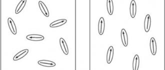
Every piece of every material is made up of billions of atoms. When they are oriented in space arbitrarily, their field fades, even in the presence of unpaired electrons. Only in stable substances can one obtain a constant orientation of electrons, that is, a permanent magnet or ferromagnet.
Some materials require an external source of magnetic field for this purpose. It is capable of orienting the rotation of electrons and giving them the desired direction, but as soon as the external field disappears, the general orientation will also disappear. Such materials are called paramagnetic materials.
A good example of a paramagnetic material is the metal door of refrigerators. It is not a magnet in itself, but it can attract magnets applied to it. Many people use this property when they use a magnet to attach a shopping list or a note to the refrigerator door.
The experimentally confirmed properties of the magnetic field are as follows:
- it is material, that is, it exists in objective reality, even if we don’t know about it;
- it is generated only by moving electric charges, that is, any moving charged body is surrounded by such a field. Magnetic fields are also created by magnets, but in this case the reason for their appearance lies in the movement of electrons. Alternating electric fields also create them;
- detect these fields by exerting some force on moving electric charges or current-carrying conductors;
- in space its propagation occurs at a speed that is equal to the speed of light in vacuum conditions.
Thus, the magnetic field, which was defined above, is a mysterious and invisible phenomenon, but at the same time completely explainable.
Permanent magnets. Earth's magnetic field
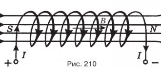
In the last lesson, we studied the magnetic field of a coil with current:
A coil with a core is called an electromagnet.
Numerous experiments on improving electromagnets have shown that if you insert a hardened steel core into a coil with current, then, unlike an iron rod, it does not demagnetize even after the current is turned off and is capable of maintaining magnetization for a long time.
Bodies that can maintain magnetization for a long time are called permanent magnets or simply magnets.
The history of magnetism goes back to ancient times, to the ancient civilizations of Asia Minor. Even 600 BC. e. In the ancient city of Magnesia in Asia Minor, a rock was discovered, samples of which attracted each other. Based on the name of the city, they began to be called magnets.
And for the first time the properties of magnetic materials were used in China: it was there that the first compass was constructed more than 4,000 years ago.
And only at the beginning of the 12th century. Magnetic compasses began to be used in Europe.
Magnets can have a variety of shapes and sizes. But the most common are strip and horseshoe magnets, which are found in any physics classroom.
It is also common to distinguish between natural
and
artificial
magnets.
Natural magnets are certain iron ores that have the ability to attract nearby small iron objects and influence the compass.
A piece of iron or its alloy can be magnetized, that is, made into an artificial magnet.
For example, if you bring a magnet close enough to a metal, it will acquire magnetic properties and will attract other iron objects. However, once the magnet is removed, it may lose its magnetization.
Are the properties of a magnet the same at different points? To answer this question, let's do the following experiment. Let's take a strip magnet and touch it with an iron ball mounted on a dynamometer. Based on the readings of the dynamometer at the moment the ball is separated from the magnet, one can judge the force of attraction of the ball to any point on it.
Experience shows that the attraction of the ball to the ends of the magnet is strongest, and it is practically not attracted to the middle of the magnet.
Those places of the magnet in which the magnetic effect is most pronounced are called magnetic poles.
Every magnet has two poles:
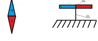
north and south
. To indicate the poles of a magnet, it is customary to color the south pole in red and the north pole in blue.
The middle of the magnet, that is, where there is no attraction, is called the neutral zone.
Note that any magnet can be demagnetized by very strong heating or other influences.
Now let's study the interaction of two magnets. To do this, let's do the following experiment. Let's attach one magnet rigidly to the tripod, and attach the other to the spring of the dynamometer.
By bringing magnets with different poles closer to each other, it is easy to notice that they begin to attract.
If you bring magnets to each other with the same poles, they will begin to repel.
In this case, the force of interaction will depend on the distance between the poles and may even be greater than or equal to the gravity force of the magnet.
Thus, the interaction of magnets has significant similarities with the interaction of electrically charged bodies. In both cases, like poles (or charges) repel, and unlike poles (or charges) attract.
A. Ampere was the first to try to explain the relationship between magnetic fields and moving electric charges. He suggested that electric currents circulate inside each molecule of a substance like iron or its alloys.
Around these currents there are magnetic fields, which lead to the appearance of the magnetic properties of matter. Ampere's hypothesis was very progressive for the beginning of the 19th century, since it was not yet known either about the structure of the atom or about the movement of charged particles - electrons around the nucleus.
But electric and magnetic interactions have one very big difference. Electric charges can be separated from each other. Think about electrification by friction or electrification through influence. And the poles of a magnet are inseparable. By cutting a magnet into pieces (whether equal or unequal), you will not separate its poles from each other, but will receive new magnets. Each of them will have a neutral zone and two poles: north and south.
The interaction of magnets is explained by the fact that there is a magnetic field around any magnet.
Let's make sure of its existence, for which we will use small magnetic arrows. Let's place them around a strip magnet. The arrows will instantly begin to move and will be located in a strictly defined order.
This means that the magnetic field existing around the magnet acted with a certain force on the magnetic needles and did work. The action of the magnetic field is confirmation of its existence.
Using iron filings, you can get an idea of the type of magnetic field of a permanent magnet.
It is not difficult to notice that the sawdust is arranged in the form of chains, with different densities around the strip magnet. This suggests that the effects that the magnet has on the sawdust are different at different points in the field. This effect is most pronounced near the poles of the magnet. The farther from the poles, the weaker this effect is, therefore, the weaker the magnetic field.
The interaction of magnets explains the principle of operation of the compass.
The compass needle is a light, strong magnet that can rotate around a vertical axis.
And what second magnet does the compass needle interact with? Our Earth is such a giant magnet. This was first proven by the English researcher W. Gilbert. He made a large diameter ball from magnetic iron ore - a “magnetic globe”. Walking around a ball with a compass, he showed that the orientation of the needle at all the points being studied completely copies its orientation at various points on the Earth.
Very simply, the Earth's magnetic field can be represented as the magnetic field of a strip magnet located between the North and South geographic poles.
The Earth's magnetic poles are located not too far from the geographic poles of our planet. That is why the poles of all magnets got their names - north and south, and designations - N
and
S
, from Dutch "
nord
" and "
here
".
Numerous observations have shown that the geographic and magnetic poles do not coincide.
Strictly speaking, the compass needle points in the direction of the magnetic meridian.
Its northern end is oriented not to the North geographic pole of the planet, but to the South magnetic pole of the Earth.
In addition, the position of the magnetic poles of our planet is constantly changing. For example, from the second half of the twentieth century. the south magnetic pole is moving quite quickly towards the Taimyr Peninsula at a speed of about 60 km/year.
Why does the Earth need a magnetic field? It is needed to protect us from unwanted cosmic radiation, in particular radiation from the Sun. It constantly emits streams of various kinds of charged particles. Their entry onto Earth in such quantities harms living organisms. The Earth's magnetic field deflects these particles, and they, obeying magnetic lines, are directed towards the poles. This is when we see the northern and southern lights.
But the invasion of such a number of particles cannot pass without a trace: it causes heating of the atmosphere and a change in the strength of some electromagnetic fields. Such phenomena are called magnetic storms.
A magnetic storm is a rapid and strong change in the Earth's magnetic field caused by strong solar radiation.
They often cause problems with electrical appliances (for example, radio interference).
And one more interesting fact: on our planet there are areas in which the compass needle deviates very strongly from the direction of the Earth’s magnetic field line - these are areas of magnetic anomalies
.
Kursk magnetic anomaly
The reason for them, in most cases, is iron ore deposits in the bowels of the Earth. One of the largest magnetic anomalies in our country and in the world is the Kursk magnetic anomaly.
How is magnetic field measured?
The magnetic field is a vector quantity and to measure/determine it you need to know its direction and strength.
To determine the direction, you can place a magnetic compass next to a magnetic object. Thus, the compass needle will stop along the field line.
Magnetic field strength is measured:
1. Either in SI units Tesla (T) or microtesla (μT)
2. Either in units of Gauss (G) or milligauss (mG), still used experimentally.
Where:
- 1 T = 10,000 Gauss
- 1 G = T
- 1 mG = 0.1 µT
How is a magnetic field created?
Magnetic fields are created by moving electrically charged particles, i.e. the field appears where electric charges move. For example, passing an electric current through a conductor.
Another way is to combine the electrons' own magnetic fields, which happens in some materials. They are called permanent magnets (for example, the magnets on our refrigerators).
If a very large charge moves at an even higher speed, then the strength of its magnetic field will also increase.
Formulas
Formula for calculating magnetic induction:
Where:
- B - magnetic field induction (in T)
- - maximum torque of magnetic forces applied to the frame (in Nm)
- l - conductor length (in m)
- S - frame area (in m²)
The formula for magnetic induction, which is created by an infinitely long conductor with current:
Where:
- B - magnetic field induction (in T)
- - magnetic permeability of vacuum (this is a constant) = (in H/m - Henry per meter)
- I - the strength of the current flowing through the conductor (in A - amperes)
- r - distance from the conductor to the point in question (in cm)
Characteristics of the magnetic field
Main characteristics:
- magnetic induction
- magnetic flux
- magnetic permeability
Magnetic induction (B)
This is the intensity of the magnetic field. The stronger a magnet or electromagnet creates a magnetic field, the greater the induction.
Formula: B = Ф/S.cos()
Where:
- B - magnetic induction (in T - Tesla)
- Ф - magnetic flux (in Wb - Weber)
- S - surface area (in m²)
- cos - angle (the angle formed between lines B with vector n, perpendicular to plane S)
Magnetic flux (F)
Magnetic induction (B) passes through a certain surface (with area S), and the induction inside it will be listed as magnetic flux (F). Formula: Ф = BS.
This is the total number of magnetic lines of force that penetrate a certain limited surface.
Magnetic permeability
Magnetic induction also depends on the environment where the magnetic field is created. This value is characterized by magnetic permeability. A medium with greater magnetic permeability will create a magnetic field with greater induction.
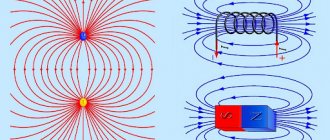
Image of magnetic field lines for some types of magnets
Let's start with an image of magnetic field lines. They are used to visualize the magnetic field. Outside a magnet, the field lines always go from the north pole to the south pole. Since the magnetic field is a closed field, they must move from south to north inside the magnet. The density of the field lines gives information about the strength of the magnetic field; The denser the field lines, the greater the magnetic field strength.
Magnetic field of a bar magnet
Figure 2 below shows the magnetic field of a bar magnet. A bar magnet is permanent and has north and south poles.
Rice. 2. Magnetic field of a bar magnet
If we compare a magnetic field with an electric field, then instead of a positive and negative pole there is a north and south. This figure shows the course of field lines from the north to the south pole. It can also be seen here that the field line density is not constant for a bar magnet. It is higher at the poles than between the poles. This suggests that the magnetic field is stronger directly at the poles than between the poles.
Magnetic field of a horseshoe magnet
Besides the bar magnet, there are other forms of permanent magnets. One important shape is the horseshoe magnet, which can be round or square.
Rice. 3. Magnetic field of a horseshoe magnet
As you can see, the magnetic field inside the horseshoe is uniform (see Figure 3). Uniformity means that the magnetic field is constant and does not depend on location. A uniform magnetic field in a field line diagram can be recognized by parallel field lines that are equally spaced. Therefore, the magnetic field strength in a uniform magnetic field is the same at every point.
Magnetic field of two bar magnets
Let's look at another example of a magnetic field (see Figure 4 below):
Rice. 4. Magnetic field of two bar magnets
These field lines show that two magnets with the same polarity repel each other. From this we can conclude that like poles repel, and different poles attract.
Magnetic field of planet Earth
But what do the poles of a magnet have to do with the north and south of the Earth? You can get closer to the answer if you ask yourself how a compass works.
Rice. 5. The compass is aligned with the magnetic field
The Earth also has a magnetic field (see Figure 5), the origin of which lies at the poles, i.e. at the north and south poles. The compass needle is a permanent bar magnet and is aligned with this field. In this case, the northern part of the compass needle is attracted to the south pole of the Earth's magnetic field. Therefore, geographic south lies on magnetic north.
Magnetic field propagation
A magnetic field is one of the forms of manifestation of electromagnetism: a field that affects moving charges, as well as magnetized bodies in different states.
The magnetic field is created by sources in the form:
- conductors through which electric current flows;
- charges and charged bodies in motion;
- bodies that are magnetized;
- variable electrical bodies.
The intensity of the magnetic field is determined using magnetic induction. This value corresponds to the applied force with which it acts on a conductor one meter long with a current flowing through it of 1 A. The unit of measurement of magnetic induction is 1 T (tesla).
Carefully! If a teacher discovers plagiarism in a work, major problems cannot be avoided (including expulsion). If you can’t write it yourself, order it here.
In the formula:
- F – is the greatest force that acts on the conductor;
- L – represents the length of the conductor;
- I – determines the current strength of charged particles in the metal.
Magnetic induction of the ring
The induction of a straight wire has a small value and decreases with distance from the conductor, therefore it is practically not used in practical devices. The most widely used magnetic fields are those created by a wire wound around a frame. Therefore, such fields are called magnetic fields of circular current. The simplest such magnetic field is possessed by an electric current flowing through a conductor, which has the shape of a circle of radius R.
In this case, two cases are of practical interest: the magnetic field at the center of the circle and the magnetic field at point P, which lies on the axis of the circle. Let's consider the first case.
Magnetic induction at the center of a circular current.
In this case, each current element dl creates an elementary magnetic induction dB in the center of the circle, which is perpendicular to the contour plane, then the Biot-Savart-Laplace law will have the form
All that remains is to integrate the resulting expression over the entire length of the circle
where μ0 is the magnetic constant, μ0 = 4π•10-7 H/m,
I – current strength in the conductor,
R is the radius of the circle into which the conductor is rolled.
Let's consider the second case, when the point at which the magnetic induction is calculated lies on the straight line x , which is perpendicular to the plane limited by the circular current.
Magnetic induction at a point lying on the axis of a circle.
In this case, the induction at point P will be the sum of the elementary inductions dBX , which in turn is a projection onto the x- of the elementary induction dB
Applying the Biot-Savart-Laplace law, we calculate the value of magnetic induction
Now let’s integrate this expression over the entire length of the circle
where μ0 is the magnetic constant, μ0 = 4π•10-7 H/m,
I – current strength in the conductor,
R is the radius of the circle into which the conductor is rolled,
x is the distance from the point at which the magnetic induction is calculated to the center of the circle.
As can be seen from the formula for x = 0, the resulting expression transforms into the formula for magnetic induction at the center of the circular current.
An empirical method for finding the speed of electromagnetic waves
The speed at which electromagnetic waves travel can be determined empirically. At the same time, stationary waves obtained in the circuit are studied. For example, such a picture can be observed when the output of the generator is connected to the line wires through capacitors. During operation of the generator, voltage fluctuations occur between the wires, which indicates the presence of electric field fluctuations. This creates an electromagnetic wave.
You can understand the intensity of vibrations at different points of the line if you turn on incandescent lamps. Thanks to such an experiment, it is possible to find out that the occurrence of standing waves in a line is caused by a certain frequency of the generator, which coincides with the natural frequency of the lines.
By measuring the distance (△x) at which neighboring nodes in a standing wave are removed, we can conclude that this value is equal to 1/2 the wavelength (λ). If you measure ν, that is, the oscillation frequency of the generator, then you can determine the speed of propagation of the electromagnetic wave using the formula:
V = λ * v
Classification
Electric fields are of two types: homogeneous and inhomogeneous.
Uniform electric field
The state of the field is determined by the spatial location of the tension lines. If the intensity vectors are identical in magnitude and they are co-directed at all points in space, then the electric field is uniform. In it, the lines of tension are located parallel.
An example is the electric field formed by opposite charges on a section of flat metal plates (see Fig. 2).
Rice. 2. Example of homogeneity
Non-uniform electric field
More often there are fields whose strengths differ at different points. Their tension lines have a complex configuration. The simplest example of inhomogeneity is an electric dipole, that is, a system of two opposite charges influencing each other (see Fig. 3). Despite the fact that the electric dipole intensity vectors form beautiful lines, but since they are not equal, such a field is inhomogeneous. Vortex fields have a more complex configuration (Figure 4). Their heterogeneity is obvious.
Rice. 3. Electric dipole
Rice. 4. Vortex fields
Oersted's experience
The most important experimental proof that a magnetic field arises due to the movement of charges is Oersted's experiment. In 1820, Oersted experimentally connected electricity and magnetism through an experiment with the deflection of a compass needle.
This phenomenon was used when the first ammeters were created, since the deflection of the needle is proportional to the magnitude of the current. It underlies any electromagnet.
And here is a video of the experiment:
What is a uniform and inhomogeneous magnetic field
A uniform magnetic field is a magnetic field at any point of which the force on the magnetic needle is the same in magnitude and direction.
In a uniform magnetic field, a charged particle moving with a speed \(\overrightarrow v\) perpendicular to the induction lines is exposed to a force \(\overrightarrow{F_л}\), constant in magnitude and directed perpendicular to the velocity vector \(\overrightarrow v\). In such a field, magnetic induction B at all points is the same in magnitude and direction.
Thanks to the Lorentz force in a uniform field, particles move uniformly in a circle with centripetal acceleration.
Carefully! If a teacher discovers plagiarism in a work, major problems cannot be avoided (including expulsion). If you can’t write it yourself, order it here.
The Lorentz force \(\overrightarrow{F_л}\) is an electromagnetic force from a magnetic field acting on a moving charge q:
\(F=qE+q\left[vB\right]\)
The invariance in absolute value of the centripetal acceleration of a particle moving with a constant velocity in absolute value means that the particle moves uniformly in a circle with radius r.
The radius r of a circle is defined as the quotient of the product of mass m with speed v and the product of electric charge q with induction B.
The radius of the trajectory of a particle with a constant mass and its speed do not affect the period of its revolution in a uniform field.
In a uniform magnetic field, the maximum torque \(M_{max}\) under the influence of closed conductors made of very thin wire of different sizes and shapes with current acquires the following properties:
- It is proportional to the current in circuit I.
- Proportional to the area of the contour.
- For contours with the same area does not depend on their shape.
Thus, the maximum torque becomes proportional to the magnetic moment \(P_{m}\) of the current-carrying circuit:
\(P_m=I\ast S.\)
The magnitude of the magnetic moment \(P_{m}\) characterizes the effect of the magnetic field on a flat circuit with current.
In this case, the value of the torque \(M_{max}\) acting on the circuit with the magnetic moment \(P_{m}\) is taken equal to unity.
Consequently, the formula for determining the induction B in a uniform magnetic field takes the form:
\(B=\frac{M_{max}}{P_m}.\)
Examples of uniform magnetic fields:
- Magnetic field inside the solenoid. A solenoid is a long cylindrical coil consisting of several turns of wire tightly wound in a spiral staircase. Each turn creates its own magnetic field, which adds up with others into a common field. It is uniform provided that the length of the coil significantly exceeds its diameter. Then inside the solenoid the field lines will be parallel to its axis and straight.
- Magnetic field inside a toroidal coil. Here the lines are closed inside the coil itself. Presented in the form of circles parallel to the torus axis. Currents in the winding of a toroidal coil flow uniformly clockwise.
A non-uniform magnetic field is a magnetic field in which the force acting on a magnetic needle placed in this field at different points of the field can be different both in magnitude and in direction.
In a non-uniform magnetic field, magnetic induction in different places has different magnitudes and directions. To calculate the value of the vector \(\overrightarrow B\) in a non-uniform field, it is necessary to determine the torque acting on it. To do this, a contour of dimensions smaller than the distances at which the field changes noticeably is placed at a certain point.
Examples of non-uniform magnetic fields:
- Outside the solenoid. The lines at the ends of the solenoid coil are not parallel to each other and extend from one end to the other. And outside, near the side surface of the coil, the field is practically absent.
- Outside the strip magnet. The magnetic field of a bar magnet is similar to the field around a solenoid. Magnetic lines stretch from one end of a magnet to the other in the direction from the north pole to the south pole. There is a neutral zone.
Differences between homogeneous and inhomogeneous magnetic fields
- A uniform field is inside a conductor or magnet, a non-uniform field is outside.
- In a uniform field, the force acting at different points is the same. In heterogeneous - different.
- The lines of a uniform magnetic field are equal in density and parallel to each other. In a non-uniform field, the lines differ in density and are curved.
- The lines of magnetic induction of a uniform field are at an equal distance from each other.
Physics 10_Appendix 1_tests with answers
“Electromagnetic induction”
Option 1
A1.
What explains the interaction of two parallel conductors with direct current?
- interaction of electric charges;
- the effect of the electric field of one conductor with current on the current in another conductor;
- the effect of the magnetic field of one conductor on the current in another conductor.
A2.
Which particle is affected by the magnetic field?
- on a moving charged one; 2. on a moving uncharged vehicle;
3. to a stationary charged one; 4. to a stationary, uncharged one.
| A3 . Which of the figures correctly shows the direction of induction of the magnetic field created by a straight conductor carrying current? 1) A; 2) B; 3) V. |
A4.
A straight conductor 10 cm long is in a uniform magnetic field with an induction of 4 Tesla and is located at an angle of 300 to the magnetic induction vector. What is the force acting on the conductor from the magnetic field if the current in the conductor is 3 A?
1)1.2 N; 2) 0.6 N; 3) 2.4 N.
| A5. There is a current-carrying conductor in a magnetic field. What is the direction of the Ampere force acting on the conductor? 1) from us; 2) to us; 3) is equal to zero. |
A6.
Electromagnetic induction is:
- a phenomenon characterizing the effect of a magnetic field on a moving charge;
- the phenomenon of the occurrence of electric current in a closed loop when the magnetic flux changes;
- a phenomenon characterizing the effect of a magnetic field on a current-carrying conductor.
A7.
A square frame with an area of 1 m2 in a uniform magnetic field with an induction of 2 T is subject to a maximum torque of 4 N∙m. what is the current in the frame?
1) 1.2A 2) 0.6A 3) 2A
IN 1.
Establish a correspondence between physical quantities and their units of measurement
| VALUES | UNITS | ||
| A) | inductance | 1) | Tesla (T) |
| B) | magnetic flux | 2) | Henry (Gn) |
| IN) | magnetic field induction | 3) | Weber (Wb) |
| 4) | Volt (V) | ||
AT 2.
A particle of mass
m
, carrying charge q, moves in a uniform magnetic field with induction
B
along a circle of radius
R
with speed
v
. What happens to the orbital radius, orbital period, and kinetic energy of the particle as its speed increases? For each position in the first column, select the corresponding position in the second and write down the selected numbers in the table under the corresponding letters
| PHYSICAL QUANTITIES | THEIR CHANGES | ||
| A) | orbital radius | 1) | will increase |
| B) | circulation period | 2) | will decrease |
| IN) | kinetic energy | 3) | Will not change |
C1.
In a coil whose inductance is 0.4 H, a self-inductive emf of 20 V has arisen. Calculate the change in current strength and energy of the magnetic field of the coil if this happened in 0.2 s.
“Electromagnetic induction”
Option 2
A1.
The rotation of a magnetic needle near a current-carrying conductor is explained by the fact that it is affected by:
- magnetic field created by charges moving in a conductor;
- electric field created by conductor charges;
- electric field created by moving charges of a conductor.
A2.
A moving electric charge creates:
- only electric field;
- both electric field and magnetic field;
- only magnetic field.
| A3 . Which of the figures correctly shows the direction of induction of the magnetic field created by a straight conductor carrying current? 1)A; 2) B; 3) V. |
A4.
A straight conductor 5 cm long is in a uniform magnetic field with an induction of 5 T and is located at an angle of 300 to the magnetic induction vector. What is the force acting on the conductor from the magnetic field if the current in the conductor is 2 A?
1)0.25 N; 2) 0.5 N; 3) 1.5 N.
| A5. There is a current-carrying conductor in a magnetic field. What is the direction of the Ampere force acting on the conductor? 1) from us; 2) to us; 3) is equal to zero. |
A6.
The Lorentz force acts
- on an uncharged particle in a magnetic field;
- to a charged particle at rest in a magnetic field;
- on a charged particle moving along the lines of magnetic induction field.
A7.
A square frame with an area of 2 m2 with a current of 2 A is subject to a maximum torque of 4 N∙m.
What is the magnetic field induction in the space under study? 1)1 T; 2) 2 T; 3) 3T. IN 1.
Establish a correspondence between physical quantities and the formulas by which these quantities are determined
| VALUES | UNITS | ||
| A) | Force acting on a current-carrying conductor from a magnetic field | 1) | |
| B) | Magnetic field energy | 2) | |
| IN) | The force acting on an electric charge moving in a magnetic field. | 3) | |
| 4) | |||
AT 2.
A particle of mass
m
, carrying a charge
q
, moves in a uniform magnetic field with induction
B
along a circle of radius
R
with speed
v.
What happens to the orbital radius, orbital period, and kinetic energy of the particle as the particle's charge increases? For each position in the first column, select the corresponding position in the second and write down the selected numbers in the table under the corresponding letters
| PHYSICAL QUANTITIES | THEIR CHANGES | ||
| A) | orbital radius | 1) | will increase |
| B) | circulation period | 2) | will decrease |
| IN) | kinetic energy | 3) | Will not change |
C1.
At what angle to the magnetic field lines with an induction of 0.5 T should a copper conductor with a cross section of 0.85 mm2 and a resistance of 0.04 Ohm move so that at a speed of 0.5 m/s an induced emf equal to 0.35 is excited at its ends IN? (copper resistivity ρ= 0.017 Ohm∙mm2/m)
“Electromagnetic induction”
Option 3
A1.
Magnetic fields are created:
- both stationary and moving electric charges;
- stationary electric charges;
- moving electric charges.
A2.
The magnetic field affects:
- only on stationary electric charges;
- only on moving electric charges;
- both moving and stationary electric charges.
| A3 . Which of the figures correctly shows the direction of induction of the magnetic field created by a straight conductor carrying current? 1)A; 2) B; 3) V. |
A4.
What force acts from a uniform magnetic field with an induction of 30 mT on a straight conductor 50 cm long located in the field, carrying a current of 12 A? The wire forms a right angle with the direction of the magnetic field induction vector.
1)18 N; 2) 1.8 N; 3) 0.18 N; 4) 0.018 N.
| A5. There is a current-carrying conductor in a magnetic field. What is the direction of the Ampere force acting on the conductor? 1)up; 2) down; 3) left; 4) to the right. |
A6.
What do the four outstretched fingers of the left hand show when determining the Ampere force?
- direction of field induction force;
- direction of current;
- direction of the Ampere force.
A7.
A magnetic field with an induction of 10 mT acts on a conductor in which the current is 50 A with a force of 50 mN. Find the length of the conductor if the field induction lines and the current are mutually perpendicular.
1)1 m; 2) 0.1 m; 3) 0.01 m; 4) 0.001 m.
IN 1.
Establish a correspondence between physical quantities and their units of measurement
| VALUES | UNITS | ||
| A) | current strength | 1) | weber (Wb) |
| B) | magnetic flux | 2) | ampere (A) |
| IN) | induced emf | 3) | tesla (T) |
| 4) | volt (V) | ||
AT 2.
A particle of mass
m
, carrying a charge
q
, moves in a uniform magnetic field with induction
B
along a circle of radius
R
with speed
v.
What happens to the orbital radius, orbital period, and kinetic energy of the particle as the magnetic field induction increases? For each position in the first column, select the corresponding position in the second and write down the selected numbers in the table under the corresponding letters
| PHYSICAL QUANTITIES | THEIR CHANGES | ||
| A) | orbital radius | 1) | will increase |
| B) | circulation period | 2) | will decrease |
| IN) | kinetic energy | 3) | Will not change |
C1.
In a coil consisting of 75 turns, the magnetic flux is 4.8∙10-3 Wb. How long does it take for this flux to disappear for an average induced emf of 0.74 V to arise in the coil?
Electromagnetic induction"
Option 4
A1.
What is observed in Oersted's experiment?
- a current-carrying conductor acts on electric charges;
- the magnetic needle turns near the current-carrying conductor;
- magnetic needle turns a charged conductor
A2.
A moving electric charge creates:
- only electric field;
- both electric field and magnetic field;
- only magnetic field.
| A3 . Which of the figures correctly shows the direction of induction of the magnetic field created by a straight conductor carrying current? 1)A; 2) B; 3) V. |
A4.
In a uniform magnetic field with an induction of 0.82 T, a conductor 1.28 m long is located perpendicular to the lines of magnetic induction. Determine the force acting on the conductor if the current in it is 18 A.
1)18.89 N; 2) 188.9 N; 3) 1.899N; 4) 0.1889 N.
| A5. There is a current-carrying conductor in a magnetic field. What is the direction of the Ampere force acting on the conductor? 1) to the right; 2) left; 3)up; 4) down. |
A6.
Induction current occurs in any closed conductive circuit if:
- The circuit is in a uniform magnetic field;
- The circuit moves forward in a uniform magnetic field;
- The magnetic flux passing through the circuit changes.
A7.
A straight conductor 0.5 m long, located perpendicular to the field lines with an induction of 0.02 T, is acted upon by a force of 0.15 N. Find the strength of the current flowing through the conductor.
1)0.15 A; 2)1.5 A; 3) 15 A; 4) 150 A.
IN 1.
Establish a correspondence between physical quantities and the formulas by which these quantities are determined
| VALUES | UNITS | ||
| A) | Induction EMF in moving conductors | 1) | |
| B) | force acting on an electric charge moving in a magnetic field | 2) | |
| IN) | magnetic flux | 3) | |
| 4) | |||
AT 2.
A particle of mass
m
, carrying a charge
q
, moves in a uniform magnetic field with induction
B
in a circle of radius
R
with speed
v U.
What happens to the orbital radius, orbital period and kinetic energy of the particle as the mass of the particle decreases? For each position in the first column, select the corresponding position in the second and write down the selected numbers in the table under the corresponding letters
| PHYSICAL QUANTITIES | THEIR CHANGES | ||
| A) | orbital radius | 1) | will increase |
| B) | circulation period | 2) | will decrease |
| IN) | kinetic energy | 3) | Will not change |
C1.
A coil with a diameter of 4 cm is located in an alternating magnetic field, the lines of force of which are parallel to the axis of the coil. When the field induction changed by 1 T for 6.28 s, an EMF of 2 V arose in the coil. How many turns does the coil have?
Assessment of tasks of parts A and B
For completing task A
the student receives
1 point
if the answer he chooses matches the answer indicated in the table.
For completing task B,
the student receives
2 points
if the set of numbers he recorded coincides with those indicated in the table;
1 point
if the answer contains at least one error;
0 points
if there is more than one error.
General rules for grading assignments C
- For completing task C, the student receives 3 points if the following elements are correctly completed in the solution:
- the equations (laws) necessary for the solution are correctly written;
— algebraic transformations and calculations were performed correctly, the correct answer was written down. The task is scored 2 points if
- an error is made in the transformations or calculations - with the original equations written correctly, there are no transformations or calculations.
the task is scored 1 point if
- an error is made in one of the initial equations - one of the required initial equations is missing.
In all other cases, a score of 0 points is given.
Table of answers to tasks in parts A, B and C
| A1 | A2 | A3 | A4 | A5 | A6 | A7 | IN 1 | AT 2 | C1 | |
| IN 1 | 3 | 1 | 3 | 2 | 2 | 2 | 3 | 231 | 131 | 10 A;20 V |
| AT 2 | 1 | 2 | 3 | 1 | 1 | 3 | 4 | 143 | 223 | 300 |
| AT 3 | 3 | 2 | 3 | 3 | 1 | 2 | 2 | 214 | 223 | 0,48 |
| AT 4 | 2 | 2 | 3 | 1 | 1 | 3 | 3 | 312 | 222 | 1000 |
Solving the tasks of part C
Option 1
Using the law of electromagnetic induction we obtain =
10 A.
Magnetic field energy =
20 V Option 2
induced emf in moving conductors →
(1)
(2) = 2 m;
a joint solution of (1) and (2) we obtain; α= 300 Option 3
According to the law of electromagnetic induction: ;
t = 0.48 s
Option 4
According to the law of electromagnetic induction; (1)
Magnetic flux (2); (3).
Solving (1), (2) and (3) together, we obtain N= 10000 turns.
Evaluation criteria
Maximum number of points – 14
What are power lines and how are they located?
Magnetic field lines or magnetic induction lines are lines whose tangents at each point have the direction of the induction vector at that point. These lines are similar to the lines of the electrostatic field strength vector.
If we imagine that there is a small magnetic needle at a certain point in the magnetic field, then under its action it will be positioned tangent to the field line at this point. The northern end of the arrow will indicate the direction of the magnetic field line.
Note: Magnetic induction lines always have neither beginning nor end, that is, they are always closed. Magnetic lines correspond to the direction of the vector at each point of the field. Vector directions are indicated by arrows.
Fields with closed vector lines are called vortex fields.
In a uniform magnetic field, all lines are parallel and equal to each other.
In a straight conductor, the magnetic induction lines are located in the form of circles lying in planes perpendicular to the conductor. The centers of the circles are on the axis of the conductor.
In order to determine the induction vector in this case, it is necessary to look along the conductor in the direction of movement of positive charges, that is, in the direction of the current. The magnetic induction vector will be directed clockwise. If the current is directed towards the observer, then the induction vector is directed counterclockwise.
1.17. Biot-Savart's law. Circulation theorem
The magnetic field of direct currents of various configurations was studied experimentally by French scientists J. Biot and F. Savard (1820). They came to the conclusion that the magnetic field induction of currents flowing through a conductor is determined by the combined action of all individual sections of the conductor. The magnetic field obeys the principle of superposition:
If a magnetic field is created by several current-carrying conductors, then the induction of the resulting field is the vector sum of the field inductions created by each conductor separately.
The induction of a conductor with current can be represented as a vector sum of elementary inductions created by individual sections of the conductor. Experimentally, it is impossible to isolate a separate section of a conductor with current, since direct currents are always closed. It is possible to measure only the total induction of the magnetic field created by all current elements. The Biot-Savart law determines the contribution to the magnetic induction of the resulting magnetic field created by a small section Δl of a conductor with current I.
Here r is the distance from a given section Δl to the observation point, α is the angle between the direction to the observation point and the direction of the current in a given section, μ0 is the magnetic constant. The direction of the vector is determined by the gimlet rule: it coincides with the direction of rotation of the gimlet handle as it moves forward along the current. Rice. 1.17.1 illustrates the Biot-Savart law using the example of the magnetic field of a straight conductor carrying current. If we sum (integrate) the contributions to the magnetic field of all individual sections of a straight conductor with current, we obtain a formula for the magnetic induction of the forward current field:
which was already given in § 1.16.
| Figure 1.17.1. Illustration of Biot–Savart's law |
The Biot-Savart law allows one to calculate the magnetic fields of currents of various configurations. It is not difficult, for example, to calculate the magnetic field in the center of a circular coil with current. This calculation leads to the formula
where R is the radius of the circular conductor.
To determine the direction of the vector, you can also use the gimlet rule, only now its handle must be rotated in the direction of the circular current, and the translational movement of the gimlet will indicate the direction of the magnetic induction vector. Magnetic field calculations are often simplified by taking into account symmetry in the configuration of the currents creating the field. In this case, you can use the theorem on the circulation of the magnetic induction vector, which in the theory of the magnetic field of currents plays the same role as the Gauss theorem in electrostatics.
Let us explain the concept of vector circulation. Let in the space where the magnetic field is created, some conditional closed circuit (not necessarily flat) is selected and the positive direction of its circuit is indicated. On each individual small section Δl of this contour, it is possible to determine the tangent component of the vector at a given location, that is, determine the projection of the vector onto the direction of the tangent to a given section of the contour (Fig. 1.17.2).
| Figure 1.17.2. Closed loop (L) with a specified bypass direction. Shown are currents I1, I2 and I3 creating a magnetic field |
The circulation of a vector is the sum of products Δl taken over the entire contour L:
Some currents creating a magnetic field may penetrate the selected circuit L, while other currents may be away from the circuit.
The circulation theorem states that the circulation of the magnetic field vector of direct currents along any circuit L is always equal to the product of the magnetic constant μ0 by the sum of all currents passing through the circuit:
As an example in Fig. Figure 1.17.2 shows several conductors with currents creating a magnetic field. Currents I2 and I3 penetrate the circuit L in opposite directions; they must be assigned different signs - currents that are associated with the selected direction of traversing the circuit by the rule of the right screw (gimlet) are considered positive. Consequently, I3 > 0, and I2 < 0. Current I1 does not penetrate circuit L.
The circulation theorem in this example is expressed by the relation:
The circulation theorem in general follows from the Biot-Savart law and the superposition principle.
The simplest example of the application of the circulation theorem is the derivation of a formula for the magnetic induction of the field of a straight conductor carrying current. Taking into account the symmetry in this problem, it is advisable to choose the contour L in the form of a circle of some radius R lying in a plane perpendicular to the conductor. The center of the circle is located at some point on the conductor. Due to symmetry, the vector is directed along a tangent, and its magnitude is the same at all points of the circle. Application of the circulation theorem leads to the relation:
whence follows the formula for the modulus of magnetic induction of the field of a straight conductor with current, given earlier.
This example shows that the theorem on the circulation of the magnetic induction vector can be used to calculate magnetic fields created by a symmetrical distribution of currents, when, from symmetry considerations, the overall structure of the field can be “guessed.”
There are many practically important examples of calculating magnetic fields using the circulation theorem. One such example is the problem of calculating the field of a toroidal coil (Fig. 1.17.3).
| Figure 1.17.3. Application of the circulation theorem to a toroidal coil |
It is assumed that the coil is wound tightly, that is, turn to turn, on a non-magnetic toroidal core. In such a coil, the lines of magnetic induction are closed inside the coil and are concentric circles. They are directed in such a way that, looking along them, we would see the current in the turns circulating clockwise. One of the induction lines of a certain radius r1 ≤ r < r2 is shown in Fig. 1.17.3. Let us apply the circulation theorem to the contour L in the form of a circle coinciding with that shown in Fig. 1.17.3 magnetic field induction line. From symmetry considerations it is clear that the magnitude of the vector is the same along this entire line. Using the circulation theorem, we can write:
| B ∙ 2πr = μ0IN, |
where N is the total number of turns, and I is the current flowing through the turns of the coil. Hence,
Thus, the magnitude of the magnetic induction vector in a toroidal coil depends on the radius r. If the coil core is thin, that is, r2 – r1 << r, then the magnetic field inside the coil is almost uniform. The quantity n = N / 2πr represents the number of turns per unit length of the coil. In this case
| B = μ 0I n. |
This expression does not include the radius of the torus, so it is also valid in the limiting case r → ∞. But in the limit, each part of the toroidal coil can be considered as a long straight coil. Such coils are called solenoids. Far from the ends of the solenoid, the magnetic induction module is expressed by the same ratio as in the case of a toroidal coil.
In Fig. Figure 1.17.4 shows the magnetic field of a coil of finite length. It should be noted that in the central part of the coil the magnetic field is almost uniform and much stronger than outside the coil. This is indicated by the density of magnetic induction lines. In the limiting case of an infinitely long solenoid, the uniform magnetic field is entirely concentrated inside it.
| Figure 1.17.4. Magnetic field of a coil of finite length. In the center of the solenoid, the magnetic field is almost uniform and significantly exceeds in magnitude the field outside the coil |
In the case of an infinitely long solenoid, the expression for the magnetic induction modulus can be obtained directly using the circulation theorem, applying it to the rectangular loop shown in Fig. 1.17.5.
| Figure 1.17.5. Application of the circulation theorem to the calculation of the magnetic field of an infinitely long solenoid |
The magnetic induction vector has a non-zero projection onto the direction of bypassing the circuit abcd only on side ab. Consequently, the circulation of the vector along the contour is equal to Bl, where l is the length of side ab. The number of turns of the solenoid piercing the circuit abcd is equal to n l, where n is the number of turns per unit length of the solenoid, and the total current passing through the circuit is I n l. According to the circulation theorem,
| B l = μ0I nl, |
where
| B = μ0 I n. |
This expression coincides with the previously obtained formula for the magnetic field of a thin toroidal coil.
| Model. Magnetic field of a circular coil with current |
| Model. Direct current magnetic field |
| Model. Solenoid magnetic field |
Magnetic field detection methods
Scheme of experiment for magnetic field detection:
- Fasten two flexible conductors parallel and vertically. For experiment, you can take conductors consisting of wire of various thicknesses and made of different types of metal. You can use steel, copper, aluminum, nichrome wire.
- Connect the poles of the current sources to their lower ends. In this case, the conductors should not repel or approach each other, since Coulomb forces do not appear when the potential difference between the charges of the conductors is insignificant.
- It is necessary to connect the conductors so that an electric current flows through them.
- In the first option, it is necessary to short-circuit the ends of the conductors so that currents of the opposite direction arise in them. The conductors must repel each other.
- In the second option, it is necessary to short-circuit the ends of the conductors to create currents in one direction. They should be attracted to each other.
Experience allows us to detect magnetic interaction, that is, the interaction between electric charges moving in a direction.
A magnetic field can be detected by its effect on electric current, that is, by its effect on moving charges.
Experiment to determine the nature of the action of a magnetic field on a current-carrying circuit:
- Hang a small flat frame consisting of several turns of wire on thin flexible conductors woven together.
- Place the wire vertically at a significantly greater distance than the dimensions of the frame.
- The frame must be positioned so that when electric current is passed through it, the wire ends up in the plane of the frame.
- When changing the direction of the current, the frame must rotate 180⁰.
Experience shows that a magnetic field is created not only by currents in conductors, but also by any directional movement of electric charges.
A magnetic field can be detected by the deflection of a nearby magnetic needle on a compass when an electric current is passed through a conductor.
The magnetic field is also created by permanent magnets. To detect it, it is necessary to suspend a flat frame with current on flexible conductors between the poles of the magnet. The frame must be rotated until its plane becomes perpendicular to the line connecting the poles of the magnet. Experiments make it possible to see the orienting effect of a magnetic field on a current-carrying frame.
Magnetic field of a current-carrying conductor
It turns out that if an electric current is passed through any conductor, a magnetic field is formed around the conductor.
Here you can recall the famous gimlet rule, but for clarity, I’d rather use the screw rule, since almost everyone has screwed in either a bolt or a self-tapping screw at least once in their life.
We screw it in clockwise - the screw goes down. In our case, it shows the direction of the electric current. The movement of our hands shows the direction of the magnetic field lines. Everything is the same when we start to unscrew the screw. It begins to climb upward, that is, in our case it shows the direction of the electric current, and at this time our hand draws the direction of the magnetic field lines in the air.
You can also often see in physics textbooks that the direction of electric current away from us is drawn as a circle with a cross, and towards us as a circle with a dot. In this case, we again imagine a self-tapping screw and in our heads we will see the direction of the magnetic field.
What do you think will happen if we make a wire loop like this? What will change in this case?
Let's look at this case in more detail. Since in this plane both conductors create a magnetic field, then in theory they should repel each other. But if they are well secured, then the fun begins. Let's look at the top view of what it looks like.
As you can see, in the region where the magnetic lines of force are summed up, the magnetic flux goes off scale.
Magnetic flux
Before you understand what electromagnetic induction is, you need to define such an entity as magnetic flux.
Imagine that you took a hoop in your hands and went outside into the rain. The heavier the rain, the more water will pass through this hoop - the greater the flow of water.
If the hoop is positioned horizontally, a lot of water will pass through it. And if you start to turn it, it’s already smaller, because it is not located at a right angle to the vertical.
Now let's place the hoop vertically - not a single drop will pass through it (unless the wind blows, of course).
Magnetic flux is essentially the same flow of water through a hoop, only we count the magnitude of the magnetic field passed through the area, not the rain.
Magnetic flux through the area S of the circuit is a scalar physical quantity equal to the product of the magnitude of the magnetic induction vector B, the surface area S penetrated by this flux, and the cosine of the angle α between the direction of the magnetic induction vector and the normal vector (perpendicular to plane of a given surface):
| Magnetic flux Ф - magnetic flux [Wb] B—magnetic induction [T] S - area of the penetrated surface [m^2] n — normal vector (perpendicular to the surface) [-] |
Magnetic flux can be visualized as a value proportional to the number of magnetic lines passing through a given area.
Depending on the angle α, the magnetic flux can be positive (α < 90°) or negative (α > 90°). If α = 90°, then the magnetic flux is 0. This depends on the magnitude of the cosine of the angle.
You can change the magnetic flux by changing the area of the circuit, the field induction module, or the location of the circuit in the magnetic field (by rotating it).
In the case of a non-uniform magnetic field and a non-flat contour, the magnetic flux is found as the sum of the magnetic fluxes penetrating the area of each of the sections into which a given surface can be divided
Magnetic interaction
Even in ancient times it was noticed that some bodies attract other bodies. Amber should be rubbed so that it attracts hair or scraps of fabric, but magnets always attract, but only iron objects. Ancient people also discovered that a magnet could cause another body made of iron to become magnetic if held close enough to the magnet. They also noticed that the two sides of a magnet have different properties—magnets facing each other can attract or repel each other.
We already know that a magnetic field arises between the poles of a magnetic material. The poles are north and south. You've probably experienced that when you bring two magnets together, they either attract or repel each other. This happens because magnetic poles with different names (north-south) attract, while poles with the same names (north-north, south-south) repel.
The magnetic field of a body is often represented as a diagram of field lines. If you introduce a ferromagnetic body into a magnetic field, it will align itself along the field lines. Ferromagnets are the most famous magnets that create a constant magnetic field.
If we hold a number of iron paper clips close to a magnet, we will notice that most of the paper clips will accumulate at the ends of the magnet (called the poles) because the magnetic force is greatest there. However, in the middle of the magnet it has the smallest value. Magnetic forces act in the space around a magnet and create the same magnetic field.
The magnetic field is invisible, but by using iron filings you can observe its effects (see Figure 1).
Rice. 1. The iron filings are arranged in a characteristic way - they form lines around the magnet. These lines show the shape of the magnetic field that has developed around the bar magnet.
Most of the iron filings accumulate near the poles, while the rest are located along the field lines. They are magnetic field lines that surround a magnet. Iron filings become magnetized, i.e. acquire magnetic properties and become small magnets that attract each other.
Electromagnetic induction
Electromagnetic induction is the phenomenon of the occurrence of current in a closed conducting circuit when the magnetic flux passing through it changes.
The phenomenon of electromagnetic induction was discovered by M. Faraday.
Michael Faraday conducted a series of experiments that helped discover the phenomenon of electromagnetic induction.
Experience once. Two coils were wound on one non-conducting base: the turns of the first coil were located between the turns of the second. The turns of one coil were closed to a galvanometer, and the second was connected to a current source.
When the key was closed and current flowed through the second coil, a current pulse arose in the first. When the switch was opened, a current pulse was also observed, but the current through the galvanometer flowed in the opposite direction.
Experience two. The first coil was connected to a current source, and the second to a galvanometer. In this case, the second coil moved relative to the first. As the coil approached or moved away, the current was recorded.
Experience three. The coil is closed to the galvanometer, and the magnet moves in (extends) relative to the coil
Here's what these experiments showed:
- Induction current occurs only when the lines of magnetic induction change.
- The direction of the current will be different when the number of lines increases and when they decrease.
- The strength of the induction current depends on the rate of change of the magnetic flux. The field itself may change, or the circuit may move in a non-uniform magnetic field.
Why does induced current occur?
Current in a circuit can exist when external forces act on free charges. The work done by these forces to move a single positive charge along a closed loop is equal to the emf.
This means that when the number of magnetic lines through the surface limited by the contour changes, an emf appears in it, which is called the induced emf.
Law of Electromagnetic Induction
The law of electromagnetic induction (Faraday's law) sounds like this:
The induced emf in a closed loop is equal and opposite in sign to the rate of change of the magnetic flux through the surface bounded by the loop.
Mathematically it can be described by the formula:
Faraday's law
Ɛi — induced emf [V]
ΔФ/Δt — rate of change of magnetic flux [Wb/s]
The “–” sign in the formula allows you to take into account the direction of the induction current. The induced current in a closed circuit is always directed so that the magnetic flux of the field created by this current through the surface bounded by the circuit would reduce those changes in the field that caused the appearance of the induced current.
If the circuit consists of N turns (that is, it is a coil), then the induced emf will be calculated as follows.
Faraday's law for a circuit of N turns
Ɛi — induced emf [V]
ΔФ/Δt — rate of change of magnetic flux [Wb/s]
N - number of turns [-]
The strength of the induction current in a closed conductive circuit with resistance R:
Ohm's law for a conductive circuit
Ɛi — induced emf [V]
I - induction current strength [A]
R - circuit resistance [Ohm]
If a conductor of length l moves with speed v in a constant uniform magnetic field with induction B the emf of electromagnetic induction is equal to:
Induction emf for a moving conductor
Ɛi — induced emf [V]
B—magnetic induction [T]
v—conductor speed [m/s]
l - conductor length [m]
The occurrence of induced emf in a conductor moving in a magnetic field is explained by the action of the Lorentz force on free charges in moving conductors. The Lorentz force plays the role of an external force in this case.
A conductor moving in a magnetic field through which an induced current flows experiences magnetic braking. The total work done by the Lorentz force is zero.
The amount of heat in the circuit is released either due to the work of an external force, which maintains the speed of the conductor unchanged, or due to a decrease in the kinetic energy of the conductor.
A change in the magnetic flux penetrating a closed circuit can occur for two reasons:
- due to movement of the circuit or its parts in a time-constant magnetic field. This is the case when conductors, and with them free charge carriers, move in a magnetic field
- due to changes in time of the magnetic field with a stationary circuit. In this case, the occurrence of induced emf can no longer be explained by the action of the Lorentz force. The phenomenon of electromagnetic induction in stationary conductors, which occurs when the surrounding magnetic field changes, is also described by Faraday's formula
Thus, the phenomena of induction in moving and stationary conductors proceed in the same way, but the physical reason for the occurrence of induction current turns out to be different in these two cases:
- in the case of moving conductors, the induced emf is due to the Lorentz force
- in the case of stationary conductors, the induced emf is a consequence of the action on free charges of the vortex electric field that occurs when the magnetic field changes.
Electromagnets and their applications
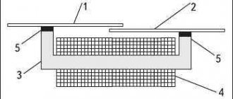
The existence of a magnetic field around a conductor carrying electric current is widely used in technology and industry. Devices called electromagnets are often used. An electromagnet consists of a coil, a core and a voltage source (see Figure 8).
Rice. 8. Electromagnet structure
The ferromagnetic core of the electromagnet plays an important role. Magnetic fields are created inside it, which enhance the magnetic field of the coil.
Small products made of ferromagnetic materials are most strongly attracted by the poles of an electromagnet. Thus, we can conclude that the magnetic field around an electromagnet is similar to the magnetic field of a bar magnet.
Application of electromagnets.
Rice. 9. Electromagnets are devices that have wide practical significance. They are used literally in everything from door locks, bells and loudspeakers to industrial equipment and high-speed trains, as well as medical and research equipment.
Electromagnets have various applications. For example, in scrap yards, electromagnetic cranes move broken cars.
Electromagnets are also used in electric locks. When an electric current passes through an electromagnet, a magnetic field is created that strongly affects the metal (steel) part of the lock (bolt). This causes the damper to move and the door to open. When the door is closed, a properly positioned spring moves the bolt and locks the lock. The lock can be opened after reconnecting the power supply.
The strongest electromagnets are used, among other things, in accelerators to control the movement of high-energy particles. Until recently, the magnetic field created by current-carrying conductors controlled the movement of electrons in television picture tubes and computer monitors.
Lenz's rule
To determine the direction of the induced current, you need to use Lenz's rule.
Academically, this rule is as follows: the induced current excited in a closed loop when the magnetic flux changes is always directed in such a way that the magnetic field it creates prevents the change in the magnetic flux causing the induced current.
Let's try a little simpler: the coil in this case is a dissatisfied granny. They take away her magnetic flux - she is unhappy and creates a magnetic field, which this magnetic flux wants to take back.
They give her a magnetic flux, take it, they say, use it, and she’s like, “Why did I give up your magnetic flux!” and creates a magnetic field, which expels this magnetic flux.