The main functions of a vector frequency generator and its scope of application
The main function of frequency converters (FCs) is to equalize the frequency of industrial current to that required by the motor. The main tasks of a directed emergency are interaction with the electric motor from the moment of starting to a complete stop, as well as protecting the mechanism and saving energy.
A vector frequency generator has the following advantages:
- the most complete accounting of the dynamics (torque, frequency, speed, angle of rotation) of an asynchronous motor with increased efficiency;
- stable control of torque on the electric motor shaft;
- quick response to load changes, can operate with instantaneous values;
- wide range of frequencies with which you can work. For example, with mechanisms at low speeds (slow speed) or at certain moments;
- copes with any work of a “scalar”.
Vector type frequency drivers are used in various mechanisms and industries:
- in fast-acting systems - roller machines, winches, elevators, special mechanisms, as well as in the production of machine tools;
- in compressors;
- in washing machines in industry;
- in metalworking (in equipment for running in);
- in extruders;
- in printing;
- in equipment for wire production;
- in injection molding machines for injection molding;
- in multi-level car parks.
Thanks to the vector orientation, we obtain stable operation at low rotation speeds.
If you need to perform complex and precise work with variable speed and torque, it is better to choose a vector frequency converter.
Description of self-connection
We suggest you consider how you can assemble and connect a simple homemade inverter frequency converter for a small three-phase electric motor yourself in the form of detailed instructions.
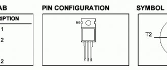
Let's consider the creation of an inverter using the example of a motor with a frequency of 400 Hz and an electrical network voltage of 27 Volts. The windings are connected in a star, due to which the middle point of each is brought out, this allows you to significantly simplify the microcircuit: you need three output signals, and one output switch for each phase. The electrical connection diagram is shown in the photo below:
Photo - Connection diagram
This device consists of the following components: a generator that generates pulses, switches on composite transistors and an electric motor.
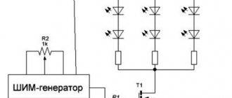
Photo - Frequency converter circuit 1
The manual for connecting the motor frequency converter is in the form of a simplified diagram. The drawing shows a motor that is controlled by several keys. Mechanical contacts are shown as semiconductor type elements. The engine is powered by constant voltage. Naturally, you cannot open the lower and upper keys at the same time, otherwise a short circuit will occur and the power of the HPV flow will drop to zero. To prevent this, you need to connect the converter in such a way that when the lower key is opened, the upper one closes. To implement this technology, special controllers are used that form a dead zone.
The time interval for the dead zone must be calculated in such a way as to guarantee the successful closing of all transistors in the upper row, only then the likelihood of through currents will be minimized.
Keys with galvanic coupling are controlled by a driver on a compound resistor; for this, an additional optocoupler is often installed for each key or channel (as shown in the diagram), this part in this drawing acts as another inverter.
To power each driver, you need to use a special rectifier, which in turn is powered from the drive winding. Perhaps this is one of the shortcomings of the scheme. To control the duration of the dead zone, this voltage and frequency converter uses a capacitor.
This device is a universal type, it can be connected to any engines whose power does not exceed 10 kW.
Management methods
The vector type of torque control and control has two methods:
- The linear method works with PWM voltage. The regulator operates with averaged discrete values, and not with instantaneous ones. Most processes use space vector modulation. The linear method includes several subtypes:
- field-oriented control;
- direct torque control with voltage FDA;
- direct torque control with the flow FDA.
- The nonlinear method is developed as a replacement for the linear method. The main advantages of the nonlinear method are ease of control, no conversion of coordinates and a rotor position sensor is required. This method achieves good dynamics.
Various variable speed control options improve the operation of the electric motor, for example, starting torque, reducing noise levels or torque pulsation.
Types of “vector” operating modes
Vector-directed frequency converters are used for accurate and high-precision calculations of speed and torque. To carry out such operations, the vector control unit contains a mathematical model (MM). Depending on the accuracy of the mathematical model of the engine, devices are distinguished:
Electric motors may or may not have feedback sensors. In the absence of a speed sensor, the frequency converter uses data from a mathematical model and the values it receives when measuring the rotor or stator current.
If a speed sensor is installed, the state of emergency additionally receives information about the speed of the rotor before the sensor, current.
It is the scope of application and equipment requirements that dictate the choice of frequency devices. For example, with a speed measurement range of 1:100 and accuracy within ±1.5%, sensorless vectorizers are used. If the measurement accuracy is high and the measurement speed is 1:10000, devices with feedback are used.
Technical differences between converters
There are many differences, let’s highlight the most basic ones, and without a scientific web of words. For a scalar (sensorless) frequency driver, the U/F relationship is linear and the speed control range is quite small. By the way, this is why at low frequencies there is not enough voltage to maintain torque, and sometimes it is necessary to adjust the voltage-frequency characteristic (VFC) to the operating conditions, the same thing happens at a maximum frequency above 50 Hz.
When rotating the shaft in a wide speed and low-frequency range, as well as meeting the requirements for automatic torque control, the vector control method with feedback is used. This reveals another difference: the scalar usually does not have such feedback.
Which emergency situations to choose? The application of one or another device is mainly guided by the scope of use of the electric drive. However, in special cases, the choice of the type of frequency converter becomes choiceless. Firstly: there is a clear, noticeable difference in price (scalar ones are much cheaper, there is no need for expensive computing cores). Therefore, cheaper production sometimes outweighs the decision-making process. Secondly: there are applications in which only their use is possible, for example, in conveyor lines, where several electric motors are synchronously controlled from a single variable frequency drive (VFD).
Difference between scalar and vector NPs
The difference between the scalar method is in the control object, areas of application, as well as technological features. “Scalars” are used in pumps, fans, conveyors, various drives, in mills, and in packaging machines.
Features of the “scalar”:
- convenience and ease of operation and adjustment of mechanisms;
- reduction of additional drive devices;
- production automation, day-night adjustment possible;
- increasing equipment efficiency - adjusting positioning, speed, frequencies;
- Possibility of smooth starting and stopping of units.
Also, the difference between the two methods lies in the object of control and management. For a “scalar”, this is the magnetic field of the stator, and for vector-directed PEs, these are the magnetic fields of the stator and rotor, which interact with each other. This interaction optimizes torque at different speeds.
The “scalar” converter uses the output frequency and current, while the “vector” converter uses the output frequency, current and its phase.
Scalars do not control torque; for this, you can install a separate torque sensor. Also, in scalars you cannot control torque and speed at the same time.
Despite the above advantages of “vectors”, many buyers often choose between it and scalar PEs. Why is this happening?
- The price for a “vector book” is significantly higher than for a “scalar book”.
- Installation and maintenance of a scalar frequency generator is cheaper and clearer than that of a “vector”.
- “Skalyarnik” can control several electric motors at once, but “vectornik” cannot.
- With a constant load, the “vector” speed fluctuates more.
Therefore, before purchasing, you need to determine the characteristics of the equipment that will regulate the frequency converter.
How to choose a frequency generator
When selecting converters, pay attention to the scope of application, the equipment on which the device will be installed, as well as the technical characteristics.
Among the technical characteristics are the following:
- power;
- frequency adjustment range;
- number of input phases;
- mains voltage;
- control method;
- number of input and output signals;
- service and maintenance under warranty.
You will find a large selection of converters at the best price on the website prompoint.ru. Using the filter in the Industrial Point online store, you can select the necessary frequency conversion devices, pump or solar panel. Find out more about products, delivery and payment from managers by phone or write to us in the feedback chat on the website.
Basic parameters
Selection of a frequency converter begins with studying the basic characteristics.
Number of supply phases and rated voltage
If these parameters are not taken into account and the equipment is connected incorrectly, emergency situations will arise and the equipment will fail.
They produce single-phase and three-phase inverter models. A single-phase network with a voltage of 220V is connected to the single-phase input, and three phases with a linear voltage of 220V or 380V are obtained at the output. Three phases are connected to three-phase, respectively.
A single-phase converter, like a three-phase one, is designed to control a three-phase asynchronous motor and is capable of solving the same problems.
It is important that the rated motor supply voltage does not exceed the inverter supply, and that the parameter values of the supply network and the electric drive match.