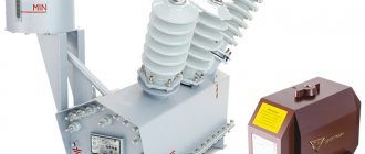
Electrical energy, from the stage of generation at power plants to supply to the networks of end consumers, undergoes a number of transformations, consisting of a change in its voltage level at electrical substations. The main elements of step-up and step-down substations are power transformers, the operating voltage of which can exceed 1000 kV. Until relatively recently, insulation and cooling of the windings of high voltage transformers was ensured by immersing their active part in transformer oil. The emergence of new technologies for the production of solid insulating materials has made it possible to design dry high-voltage transformers.
Design and operating principle
The design of such a device is similar to a conventional oil unit. The transformer consists of the following main components:
Dry transformer design
- magnetic circuit (ring-shaped, rod or armored structure) - acting as a transmission of electromotive force between the windings at the input and output. For its manufacture, laminated, strip or plate steel is usually used;
Types of magnetic cores - windings - electric current flows through them and an electromagnetic effect is formed;
Dry transformer windings - winding insulation - to separate live parts from each other and surrounding objects;
- connecting elements - couplers, bolts, strut frames and other auxiliary parts;
- housing, inside of which the main components are located;
Frame - insulators - for connecting contacts to the unit.
The principle of operation is based on the generation of electric current in the secondary winding due to the induced EMF on the primary coil after voltage is applied to it, with the transformation of characteristics due to the difference in the number of turns at the input and output.
Design and principle of operation of a power transformer
An electrical conversion unit or voltage transformer has several main structural elements:
- The housing - of various types, depending on the installation details, may have a different design, but its main task is to reliably contain and safely isolate the entire electrical part of the energy conversion device from surrounding processes.
- The primary winding is the input of the device (input) - a coil with copper conductors, a certain number of turns, cross-section, type, the internal part of which is connected to external contact terminals mounted on an insulating base. Depending on the general functionality of the transformer (step-up/step-down type), conductive elements are connected to its contact part to further carry out the transformation process. The winding of the primary type, like the secondary one, is connected (wound) to a structural part of the magnetic circuit - a mandatory requirement for performing the main transformation process.
- The secondary winding is the output contact part of the converter. Depending on the general functionality of the equipment, it has its own characteristics and design, the cross-section of the conductor in its coil winding.
- Magnetic core is a structure made of electrically laminated, pressed steel, or ferromagnetic materials, of a certain structure and shape, uniting both windings with its “body”. Thanks to its closed circuit, electromagnetic laws are practically implemented, which makes it possible to carry out the process of energy transformation according to voltage class.
- Additional element base if you scale the transformer devices according to their purpose and scope. It includes all other elements that make up the voltage converter.
The structure of a voltage transformer is most clearly shown in Figure 1.
Figure 1. Detailed design and structure of a voltage transformer
Radiators, insulators, expansion tank and other additional parts may vary depending on the type of specific electrical equipment.
It is easy to explain in detail the principle of operation of the voltage converter based on the equipment diagram:
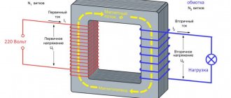
There is a primary, input winding made of usually copper conductors wound on a magnetic circuit, to which a certain voltage value is applied, and a secondary (output) winding, from the output terminals of which the voltage is removed, but already reduced to the required voltage value. Both windings are wound on the sides of the core and have no electrical connection with each other. The core, also known as the magnetic circuit, according to the law of electromagnetic induction, implements the entire process of voltage conversion in the device.
Figure 2. Transformer operating principle
Alternating current (varying over time with an operating frequency of 50 Hz) enters the input of the primary winding and flows through all the conductors of this coil, thereby inducing an EMF from its side of the core. According to the law of electromagnetic induction, a magnetic flux of a certain magnitude is induced in the magnetic circuit and begins to circulate. This magnetic field, in the course of a circular motion along the core, passes through the conductors of the secondary winding of the device, which is wound on the opposite side of the equipment and induces its own EMF of a smaller magnitude there (the example considers the step-down type of device). The magnitude of the EMF of the secondary winding by its action creates the rated current and voltage on the secondary winding, which are removed from its output terminals and are the result of the entire operation of the electric converter.
By changing the design of the core, the cross-section, the type of conductors and the number of turns in each of the windings, it is possible to vary the principle of operation of the equipment, using it as a step-down unit for transmitting electrical energy from the power source to the consumer, a step-up element as part of the “Generator-Transformer-Power Line” installation, or a transmission an element when it is necessary not to change the voltage value, but to use it in relay protection systems as a safe device that provides galvanic isolation for automation and protection.
Peculiarities
Dry transformers differ in the type of windings used, which are open, monolithic and cast types. The use of the last two varieties is limited due to poorer heat dissipation. Because of this, wire with a larger cross-section is used for such coils. And for cooling, it is necessary to increase the gaps between the windings and the housing, make special windows to improve air circulation and organize forced airflow.
The following cooling systems are used for dry insulation transformers:
- air, with natural heat removal - the temperature of heating units is reduced due to direct contact with the air, through the process of convection and air circulation;
- forced air - the air flow is directed by a fan to the windings, inside the housing, to ensure a reduction in the temperature of the components.
An air cooling system with natural heat removal for high-power units requires an increase in the size of the housing, which leads to an increase in the weight and cost of the equipment, which is not always acceptable.
Installing cooling fans can reduce the price and improve the performance of the unit.
What is a dry-type transformer?
The concept of a dry transformer implies that the space between the windings and the housing is not filled with liquid dielectric. The idea of dry converters appeared relatively long ago, but their practical implementation was hampered in every possible way due to the lack of suitable technical means.
Therefore, at the initial stages they were made for indoor installation in dry rooms, low-power devices with a closed housing, laboratory samples, etc. But with the advent of technologies and materials that made it possible not to accumulate moisture from the surrounding space, their scope of application expanded to the open part of high-voltage electrical installations.
Specifications
- Rated power - determines the volume of processed electricity for a dry transformer.
- Rated voltage - shows the value of the voltage level that can be supplied to each of the high, medium and low potential windings.
- Overload factor – shows by what amount the workload can exceed the rated current value.
- No-load and short-circuit loss coefficients
- The degree of dust-moisture resistance and climatic performance determines the external conditions under which the unit can be operated and the insulation strength is maintained.
- Overall dimensions and weight of a dry-type transformer.
- Noise level.
To enlarge the table with characteristics, click on it:
Temperature relay connection diagrams
The temperature control system for dry voltage converters on all three phases and at several points of the core is implemented automatically based on the connection of a thermal relay of the RT 100 type, connected via temperature sensors to the temperature measurement points of the operating equipment.
The thermal relay is located on the housing of the power plant in a place on the housing convenient for maintenance and reading indicators on a universal DIN rail.
The connection diagram for the contact parts of the thermal relay control to the transformer is given below.
Figure 5. Thermal relay RT 100
The limit of maximum and minimum response thresholds for signaling an emergency or shutdown mode of a power device can be set by maintenance personnel, but it should not exceed the permissible values of 140-1500 C for the standard insulation resistance class and higher for more reinforced ones. In Table. 6 these characteristics are described in detail for each class.
The relay is connected to the power supply through modular differential protection, and is also connected by its contacts to the power coils of cooling fans of certain areas of dry-type equipment, when the PT 100 is triggered, which begin forced airflow into these areas of the device.
Advantages and disadvantages
Compared to oil-based ones, dry transformers have the following advantages:
- environmental safety - their operation does not involve the use of toxic substances with the subsequent need for their disposal. This significantly reduces the negative impact on the environment,
- ease of maintenance - no need to constantly replace and top up oil, control the tightness of components,
- safety in operation - such devices have a significantly lower fire hazard and risk of fire, the threat of thermal expansion of the oil with a possible explosion is eliminated,
- simplicity of design - this reduces the cost of production and ensures reliable operation,
- light weight - which is especially important for units of significant power due to the fact that no liquid dielectric is used.
Comparison of oil, dry and air transformers
Comparison of oil and dry transformers
Economic benefits of a dry-type transformer
Disadvantages are associated with relatively large dimensions. For powerful machines, it becomes necessary to significantly increase the volume of the case in order to increase the air gap for cooling.
The use of cast insulation poses a risk of mechanical failure when operating in conditions of low temperatures or sudden temperature fluctuations.
Service
Despite the shortcomings, dry transformer devices are often used in various areas of human activity. Maintenance of the unit is simple. The inspection is carried out once every 6 months. At the same time, the ventilation system is checked.
Caring for the unit also involves periodically cleaning it from various contaminants. The frequency of cleaning depends on the environment. In dusty rooms, maintenance of the surface of the device must be performed more often.
Maintenance involves an external inspection of the equipment. There should be no defects or mechanical damage on it. Fasteners must be tightly tightened. Bolts are checked once a year. By following simple maintenance recommendations, you can ensure long-term, reliable operation of the unit.
Application area
This equipment is widely used in the domestic and industrial spheres. Dry-type transformers are used to convert electrical energy in enterprises in the following areas:
- Traction and transformer substations for energy transmission,
- Drives of ground electric transport,
- Power supply for production workshops, etc.
In everyday life, such machines are installed to supply converted energy to residential buildings and public institutions. Miniature devices are used to connect various household equipment.
Permissible overloads
Dry-type power transformers are divided depending on the heating class of insulation resistance according to established standards. Based on them, there is a parametric table of tolerances for temperature overloads of power devices.
Table 6. Permissible overloads of dry type transformers
| Device insulation type according to heating resistance class with temperature range | Triggering of thermal probes installed on the transformer upon an “ALARM” | Triggering of thermal probes installed on the transformer upon the “SHUTDOWN” signal |
| Class "B" = -50 to 1200 C | 1200 C | 1300 C |
| Class "F" = -50 to 1550 C | 1400 C | 1500 C |
| Class "H" = -50 to 1800 C | 1600 C | 1700 C |
Thus, if dry transformers are selected in a climatic zone with an increased temperature balance for long-term operation, it is imperative to select them with an insulation resistance heating class of at least “H”, based on the values given above.
Vacuum Impregnation Insulation (VPI)
This technology creates a varnish coating on conductors by alternating cycles of pressure and vacuum. The VPI process uses polyester resins. It provides conductors with better varnish coverage than conventional dipping. The coils coated with it are then placed in an oven where baking occurs. They turn out to be much more resistant to corona discharges. What does such a transformer look like? His photo is posted below.
three-phase dry voltage class 6 | 10 | 20 kV with insulation heat resistance class H (180ºC)
NIPO RusEnergo offers converter transformers of the TS and TSZ types for delivery. The use of transformers is due to the use of electrical installations with consumed direct and alternating current in drilling rigs; railway power supply; excitation systems; in ferrous and non-ferrous metallurgy, in the coal industry, oil and gas sector, chemical industry and transport for railway and urban transport, in the metro, and in other areas of industry and urban infrastructure.
What's on the Russian market?
It is worth noting that in recent years a steady tendency has formed in Russia to repeat the experience of Europe, where up to 90% of all newly installed transformers are of the dry type. The market reacts accordingly. Today in the Russian Federation there are offers of such devices from two groups of manufacturers. The first of them includes Russian, Italian, Chinese and Korean brands. Basically, constructive analogues of well-known Russian brands are offered: TSZ, TSL, TSGL. How much does such a dry transformer cost? The price of a typical “thousander” varies from 900 thousand to 1 million rubles.
The second group includes German and French manufacturers. They offer brands of the DTTH, GDNN, GDHN series. How much will such an imported transformer cost? The price of the same “thousander” will be from 1.5 to 2 million rubles.
Main settings
The most crucial moment in the operation of the devices in question is ensuring the temperature conditions of the windings. To help in choosing or purchasing a dry type apparatus for power supply to various facilities, let’s consider several basic operational parameters:
- Power, kVA.
- Rated voltage of the primary and secondary windings.
- The heat transfer of an insulating system is the sum of the maximum ambient temperature + the average temperature rise in the windings + the difference between the average temperature rise in the windings and the highest value in them.
- Core and coils - of particular importance are possible damage to the core or accumulation of delaminations (copper or aluminum conductors).
There are various design types of transformers, determined primarily by the methods used to insulate their windings. Among them are known: vacuum impregnation, encapsulation and cast coil. Let's consider each of them separately.
How to arrange ventilation in compartments
For optimal creation and implementation of natural air cooling of a power transforming unit, electricity is necessary in the compartments where its permanent installation and connection is planned, the creation of a correct supply and exhaust ventilation scheme.
Some recommendations for creating them in a short diagram and with a short description are given below.
Figure 6. Creation of ventilation for dry transformers in their operating area
Calculation of the selection of the supply and exhaust openings indicated in Fig. 6 S1/S2 is produced using special calculation formulas and depends on several parameters of the power converter, as well as on the dimensions of the compartment itself in which the installation takes place. It is better to entrust these calculations either to computerized services for calculating technical parameters for optimal operation of transformers or to attribute them to the design bureaus that design the future electrical installation or part of it.
A few words about ventilation
By equipping the transformer with a blowing fan, the load can be significantly increased. Thus, for cast windings, such a function can increase the long-term permissible load by 50% above the rated one. For VPE or VPI types, the power increase in this case can be up to 33%.
For example, the power of a standard transformer of 3000 kVA with a cast winding, when equipped with a blower fan, increases to 4500 kVA (by 50%). At the same time, a VPE or VPI type with a power of 2500 kVA with a fan will raise it to 3.333 kVA (33%).
However, you should always take into account that the presence of a blower reduces the overall reliability of the system. If, when working with airflow under a load higher than the rated one, the fan fails, then there is a real risk of a serious accident, as a result of which the entire transformer can be lost.
Cast coils (in molded compacted epoxy resin)
These devices contain coils encapsulated in epoxy resin during the molding process. They are completely filled with resin under vacuum.
Each winding insulation method is specifically suited to specific environments. It is very important to understand where to use the appropriate types of devices. For example, dry-type cast resin transformers cost approximately 50% more than VPE or VPI products. Thus, the choice of a specific device type can significantly affect the overall cost of the project.
