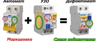
Circuit breaker (automatic)
is an installation electrical product designed to protect electrical wiring from electric current exceeding the permissible value by opening the load circuit.
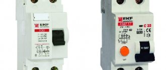
The photograph shows a modular single-pole circuit breaker of type BA101 with shutdown characteristic C, designed for operation in an alternating voltage network of 220 V and rated for a protection current of 10 A. These data are usually indicated on the front panel of the machine.
Automatic switches are produced in accordance with the technical requirements of GOST 9098-78 “Low-voltage automatic switches”.
The machine simultaneously performs two types of electrical wiring protection - against instantaneous current surges, for example, in the event of a short circuit in the electrical wiring that exceeds several times the rated one, and slow thermal protection, which is triggered when the rated load current is slightly exceeded for 15-60 minutes.
Thermal protection is made specially slow to eliminate false alarms of the machine. For example, a machine with a nominal value of 25 A is loaded with a current of 15 A. You turned on a vacuum cleaner, which will add another 10 A. But at the moment of starting, any engine consumes a current much higher than the rated one, and when the vacuum cleaner was turned on, its current consumption could momentarily increase to 15 A. As a result for a short time, the current flowing through the machine will be 30 A. But due to the inertia of the thermal protection, the machine does not operate.
How to choose a circuit breaker
Automatic circuit breakers in accordance with GOST 9098-78 are produced for the following protection currents: 1, 2, 3, 6, 10, 16, 20, 25, 32, 40, 50 and 63 A. You can select from this range the circuit breaker required for the protection current using below presented in the table only after determining the cross-section of the electrical wiring wire.
| Table for selecting a machine for protecting household single-phase electrical wiring depending on the cross-section of the copper wire | |||||||||||
| Wire core cross-sections, mm2 | 1,0 | 1,2 | 1,5 | 2,0 | 2,5 | 3,0 | 4,0 | 5,0 | 6,0 | 8,0 | 10,0 |
| Wire core diameter, mm | 1,1 | 1,2 | 1,4 | 1,6 | 1,8 | 2,0 | 2,3 | 2,5 | 2,7 | 3,2 | 3,6 |
| Rated load current of the wire, A | 5 | 6 | 7 | 10 | 16 | 20 | 25 | 32 | 40 | 50 | 63 |
| Rated load power, kW | 1,1 | 1,3 | 1,6 | 2,2 | 3,5 | 4,4 | 5,5 | 7,0 | 8,8 | 11 | 14 |
| Rated current of the circuit breaker, A | 3 | 6 | 6 | 10 | 16 | 16 | 25 | 25 | 32 | 50 | 50 |
In addition to the protection current, the circuit breaker must be designed to operate in an AC power supply with a voltage of 220 V
, with a frequency of
50 Hz
, with a shutdown characteristic
of type C
(the current value at which the machine will operate is equal to the rated current of the machine, multiplied by 5-10) and
class 3
(operation time less than 1/3 of the half-cycle of a sinusoid).
When choosing a machine, you need to take into account that the real current of its protection is greater than that indicated in the passport. Therefore, when choosing according to the table, if the load current does not fall into the standard range of circuit breakers, then you must select a circuit breaker with a lower protection current. For example, the calculated cross-section of the electrical wiring turned out to be 3.0 mm2, the rated load current is 20 A. In this case, you need to select a circuit breaker with a protection current of 16 A.
It is important to note that when choosing a machine, you should take into account not only the cross-section of the electrical wiring in the apartment, but also the cross-section of the wires coming to the meter. It may well turn out that the new electrical wiring in the apartment is laid with a wire with a cross-section of 4.0 mm2, and a wire with a cross-section of 3.0 mm2 comes from the entrance panel. In this case, you need to select a machine based on a smaller wire cross-section, or replace the wires suitable for the meter with wires of a larger core cross-section.
The circuit breaker is intended solely to protect electrical wiring from destruction. To protect electrical appliances, they are equipped with their own protection, usually in the form of a fuse.
Types of Circuit Breakers
, type C circuit breakers are usually installed
.
| Table for selecting the type of machine depending on the type of load | ||
| Type of time characteristic of the machine | Operation current, A | Type of load |
| B | In×3…5 | Lighting and socket circuits for resistive loads (heater, iron) |
| C | In×5…10 | Inductive and capacitive (motors) |
| D | In×10…20 | Power transformers, heavy-start motors, lighting systems |
| Z | In×2…3 | Semiconductor devices, cables |
| K | In×8…15 | Motors transformers, electronics |
| S | In×1 | Contactors, motors, instrument transformers |
Note. In is the rated protection current of the machine, indicated on its front panel.
Specifications
Naturally, each model has certain power and throughput parameters. We propose to consider the technical characteristics of an automatic single-pole circuit breaker type ABB (ABB):
- Initial network voltage – 230–400 V;
- Rated (initial) current – 16A;
- Frequency – 50Hz;
- Capacity (up to a switch with a power of 60 A) – at least 4.5 kA;
- Operability up to 10 thousand shutdowns and starts;
- Guaranteed circuit strength - up to 10 thousand shutdowns and starts;
- There is one pole (hence the name “single-pole”), in contrast to a two-pole machine, which, accordingly, has two of them;
- Fire safety class and protection against penetration of water and solid particles under the body - 20IP;
- The maximum connection wire size is 25 mm 2 ;
- Shutdown speed - less than 0.1 seconds;
- The current determines the certificate of a specific device.
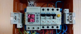
From this series, the BM40 automatic modular switch is most often used. It is known for its ability to pass up to 32 Amperes, while providing a maximum number of operating cycles (off-on) - up to 30. The Legrand, Schneider electric Multi9 (25 A), Merlin Gerin and ABB automatic machines also operate in a similar manner SH201-B6.
Photo - marking of single-pole circuit breakers
In addition, single-pole circuit breakers are also divided into types :
- A – this type is used to connect group loads in residential buildings or apartments, used in domestic conditions;
- B – used to protect networks that are connected to heavy loads. Most often these are personal lighting or homes with increased energy consumption needs. Used in systems with a ratio of 3÷5 In;
- C – necessary for connecting industrial buildings, factories, companies and other industrial networks.
Video: Connecting a single-pole circuit breaker
Electrical diagram for connecting circuit breakers
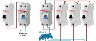
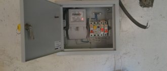
The drawing shows a block diagram of modern apartment electrical wiring. Automatic switches are usually installed in a panel next to the electric meter and are connected to the break in the phase wire coming from it if there is no RCD.
It is customary to connect the phase wire from the meter to the top terminal of the machine. Electrical wires going to electrical appliances are connected to the bottom terminal.
It is recommended to lay separate electrical wiring lines for the lighting system and sockets and install its own circuit breaker for each. For electrical appliances with high current consumption, for example, a washing machine, an electric oven, it is also recommended to install individual electrical wiring with a circuit breaker, as shown in the diagram.
Design and principle of operation of a circuit breaker
If you remove the side wall of the circuit breaker, the picture shown in the photograph will open before your eyes. It is easy to study the design of the machine and the principle of its operation.
When the control knob is set to the “On” position, as shown in the photo, the current from the meter output is supplied through a wire to the upper screw terminal (pictured on the right), then through the break contacts through the solenoid coil and the bimetal heater to the screw terminal. An electrical wire is connected to the terminal to connect electrical appliances.
The machine remains in this state until the current consumption of electrical appliances exceeds the set one. If the current suddenly exceeds the protection current of the machine, then the electromagnetic field in the solenoid winding will increase to a value sufficient to overcome the force of the spring to pull the core into the coil. When shifted to the left, the core will press on the lever of the release mechanism. As a result, the opening contacts will separate and the control knob will turn counterclockwise.
Thermal protection works in the same way, only the release mechanism is triggered as a result of bending the bimetallic plate. A spiral is wound on the plate through which the main current passes. If the current flowing through the spiral for a long time slightly exceeds the protection current, then the bimetallic plate bends to such an extent that the release mechanism is activated.
To extinguish the electric arc that occurs when the contacts open, an arc-extinguishing chamber is installed in the machines, which protects the breaking contacts at the moment of opening when large currents flow through them from burnout.
Bipolar
With this connection of AV in single-phase networks, three types of conductor are used - grounding, power and neutral. The input contacts located on the top of the AB are marked with odd numbers, and the output with even numbers.
The supply wire is connected to input 1, after which it is tightly clamped into the terminal. The neutral, suitable for terminal 3, is connected in an identical way. Then the power core is passed through the meter and distributed evenly across all groups of switches. From pin 4, the yellow-green wire is connected to the ground bus by passing through the three-phase reading and protection blocks.
Mounting the machine in the panel on a DIN rail
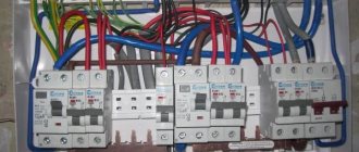
In a wall panel or boxes, circuit breakers, like other electrical installation devices, are mounted on a DIN rail, also often called a mounting rail. It is a metal plate 35 mm wide, curved in such a way that its longitudinal edges are raised. According to GOST R IEC 60715-2003 “Low-voltage distribution and control equipment. Installation and fastening on rails of electrical devices in low-voltage complete distribution and control devices" is designated T35
.
This method of fastening does not require additional fasteners and allows you to quickly install and remove machines for maintenance, inspection or replacement. The photo shows an old-style DIN rail, when they were an aluminum alloy profile.
DIN rails are installed horizontally in the panel. There are two latches on the back of the circuit breaker - a stationary one (pictured on the left) and a spring-loaded movable one (on the right). Thus, to install the machine on the rail, you need to place the upper fixed clamp over the edge of the DIN rail, and then press the lower part against it. The movable latch will sink into the body of the machine and come out of it when the machine is pressed with its entire plane against the DIN rail.
To remove the machine from the DIN rail, simply insert the end of the blade of a flat-head screwdriver located below the exiting conductor into the ear of the movable clamp and push it down. The latch will disengage and the lower part of the machine will freely move away from the DIN rail.
The connected circuit breaker is under phase voltage and must be de-energized before dismantling.
How to properly connect the wires to the machine
The uninterrupted operation of all electrical wiring is determined not only by the correct choice of wire cross-section and electrical appliances, but also by the reliability of their connections to each other. Despite the simplicity of this operation, mistakes are often made, which subsequently leads to burnt contacts and failure of circuit breakers.
If the insulation is not removed to an insufficient length, it may get under the clamping strip of the terminal and will subsequently lead to poor contact and charring of the connection.
When removing insulation with a knife, you need to place its blade parallel to the wire, then notches will not appear on the copper core, leading to a fracture in this place of the wire when bending.
To increase the contact area between the terminal and the wire, I recommend that, if the terminal window allows, bend its end, as shown in the photo.
The picture shows a view of the machine from the screw terminals side. To connect the wires, simply unscrew the screw, insert the end of the freed wire from the insulation for a length of about 10-15 mm until it stops at the terminal, and screw the screw back in with sufficient force.
After clamping the wire, you need to pull it with considerable force to make sure that it is securely fastened. When inserted into the hole of the terminal, the wire may slip past, the screw will be tightened without clamping it between the contacts.
Installation
Before installing protective devices, it is necessary to determine in advance how many wires can be connected to the machine, how the supply wires will be connected, and only after that think about connecting the circuit breaker to the electrical circuit. If there is any doubt, it is better to refer to the basics of electrical installation. They describe in detail how to correctly connect circuit breakers in an electrical panel, prepare wires and carry out maintenance of electrical panels.
To install the machine in the electrical panel, you will need some tools and materials.:
- Cables of the same cross-section for the main circuit and jumpers when installing several circuit breakers.
- Insulating tape.
- Knife for removing insulation from ends.
- Screwdrivers of various types - Phillips or slotted.
- Devices for determining phase - indicator or multimeter.
- Pliers or regular wire cutters.
In order to understand what actions need to be performed in different situations, you need to consider different connection methods - single-pole and double-pole.
Why is it unacceptable to install a circuit breaker on the neutral wire?
I corresponded via email with Volodymirom about the inadmissibility of installing a circuit breaker on the neutral wire of the electrical wiring. For those who want to understand the intricacies of this issue, I think its result will be useful.
Volodymyr:
I'm currently installing an electrical panel in my apartment and a question has arisen. Why can’t separate machines be set to zero and phase, but only paired ones? Why “It is strictly prohibited to install a single circuit breaker on the neutral wire.”?
Answer:
When installing separate circuit breakers on the neutral and phase wires, designed for the same protection current, in the event of an overload of the electrical wiring, only one of them is likely to work. This is due to the fact that circuit breakers have a variation in the magnitude of the operating current. If the machine installed on the neutral wire is triggered, then all electrical wiring, including the neutral wire, will be under phase voltage. The phase will reach the neutral wire through electrical appliances that are turned on at this time, for example, a TV in standby mode, a refrigerator. And if a person thinks that since the machine has worked, it means that the wires are de-energized and, therefore, safe, then he can start repairing the electrical wiring and accidentally come under dangerous voltage.
That's why it's impossible. It is possible to install twin circuit breakers in household electrical wiring, but there is no point in this, only extra costs, since a paired circuit breaker costs much more. Therefore, the neutral wire is laid directly, and a machine must be installed on the phase wire.
Volodymyr:
If during a short circuit the zero-machine is knocked out faster, and the phase-man-earth short circuit continues, then the phase-machine will still be knocked out. Also, both can work approximately simultaneously. That is, the machine must be set to zero more powerful than the phase one. But there will be no disruptions to the network, only additional costs.
Answer:
If the phase-person-ground short circuit continues,” then the person will die before the circuit breaker on the phase wire is triggered. The lethal current through the human body is only 0.1 A, and a 10 A machine will only work when a current of more than 10 A flows through it. Therefore, the PUE categorically prohibits the installation of a separate machine on the neutral wire.
You can, of course, install a machine designed for a higher current on the neutral wire, but where is the guarantee that the machine will not fail? After all, the main value for any person is his health and life! Therefore, even with the hypothetical possibility of causing harm to a person, they do everything to exclude it.
Volodymyr:
I am just beginning to master electrical installation in practice, including using your recommendations. And I want to understand the technical side in order to better understand the recommendations of the PUE. So forgive me if I'm wrong somewhere.
There are two common situations: 1. Phase-to-human-earth or phase-to-earth short circuit. A phase machine will work here. Zero machine has nothing to do with it. 2. Short circuit phase-man-zero or phase-zero. A phase machine and/or a zero machine will work here. That is, if the phase machine does not work, then the zero one will break the circuit. Accordingly, the circuit breaker to zero will not be a hindrance, but only additional protection when it is not possible to install a more expensive two-pole circuit breaker that cuts off the line completely. The only inconvenience, as you wrote, if during a short circuit only zero is knocked out, then we will not know whether the phase is knocked out.
Answer:
Your reasoning is based on the assumption that the machine serves to protect a person from electric shock. But the machine is designed solely to protect electrical wiring from destruction if the current flowing through it exceeds the permissible limit. To protect people, an RCD is installed. The situations you described involving a person will not lead to the machine being turned off, since the person will die instantly if the current flowing through his body is more than 0.1 A.
According to Ohm's law, current can only flow through a closed circuit and in the event of a short circuit, it does not matter which wire is broken, phase or neutral. From this point of view, you can put one machine on the phase or neutral wire, or, if there is nowhere to put the money, sequentially, at least 10 machines on both the zero and phase wires. The wires will be protected. The machine is placed on the phase wire only so that when the machine is triggered, the possibility of a person coming under life-threatening voltage is completely eliminated.
Let me give you an example: a man decided to replace a light bulb in a chandelier and turned off only the switch, and not the machine, this is usually what they do. The wiring in the chandelier was old, and the neutral wire was touching the metal body of the chandelier. The man stood on the ground and, screwing in the light bulb, held the chandelier by the metal body with one hand. At this time, another family member decided to turn on an electrical appliance, whose insulation at the exit from the plug had frayed and the wires were short-circuited. A short circuit occurred, and only the circuit breaker installed on the neutral wire worked, and a phase appeared on the neutral wire of the entire apartment wiring. As a result, a person changing a light bulb can receive an even fatal electric shock. The machine can also work when the lights are turned on if the light bulb burns out at that moment.
PUEs are written based on accidents involving electric shock to people and it is impossible to describe all situations in which people were injured or died. You just need to follow the PUE and then the electrical wiring will never fail.