An acoustic switch is quite an entertaining and interesting device, which is very useful to assemble for a novice electronics engineer or radio amateur to improve their skills. Let's look at how to make an acoustic switch with your own hands from available radio elements.
The principle of operation of such a device is that a sound signal, usually a clap of the hands, is perceived by a microphone, after which the load is connected or disconnected using various circuit solutions. Most often, the load is an incandescent lamp or an LED lamp.
Manufacturers
The most famous models presented on the Russian market are “Ecosvet” and “Claps”. Let's look at their main characteristics.
Switch "Сlaps"
One of the newest developments is the “Claps” cotton switch model. In this device, the sound is processed using a microprocessor; it does not react to any extraneous noise, but is tuned to several claps in a row (this is the most important operating condition).
It is permissible to install several such switches in one room, each of them will react to a certain number of claps, and accordingly turn on the light, humidifier, fan, TV or stereo system. This switch model is suitable for any household appliances that have an electrical cord.
Perhaps to some, the clap switch may seem like a toy or a completely unnecessary device. Others, on the contrary, are passionate about the idea of creating their own “smart home” so that lights and electrical appliances turn on and start working on command or clap. Arrange your life the way you want, but at the same time make it as comfortable as possible.
Ecolight switch
The Ecosvet device is designed to work with 220 Volt light bulbs.
Main parameters of the device:
- load - 300 Watt;
- sound signal spread - from 30 to 150 decibels;
- housing protection level - IP30;
- permissible temperature range - from 20 degrees below zero to 40 degrees above zero;
- cost - from 350 rubles.
“Ekosvet” is fixed with self-tapping screws using the mounting legs. It is not recommended to install the device in noisy rooms. Despite the fact that “Ekosvet” is configured to clap, false alarms are possible.
The figure above shows the device connection diagram. "Ecolight" is connected to a conventional switch to provide the ability to de-energize the circuit and stop its operation.
With microcontroller
A microcontroller is a small piece of silicon covered in plastic and has metal terminals that does not perform any functions without software. Its use in any appliance makes it smart and involves use in the Smart Home system.
Difference from standard sound switch:
- reduced response time to 100 microseconds;
- possibility of reprogramming, setting individual parameters;
- increased range;
- the ability to change the signal threshold value (to eliminate interference and avoid responding to false commands);
- smooth change in lighting brightness;
- fewer components;
- short circuit protection.
Types of switches for home (domestic use)
The various types of switches used in everyday life must be convenient, safe, and have an attractive design. They differ from each other in types and types. Depending on the installation method, the switch can be built-in or installed externally. Nowadays, a rotary key is most often used as controls; such switches are common in Europe.
Types of switches for the home
In the USA they prefer to use lever-type switches (toggle switches), apparently not wanting to break away from tradition. But this is now, but in the old days, when Thomas Edison just made his invention, rotary switches were used. They were known throughout the world in the first half of the 20th century and switched up to several circuits in 3–4 positions (batch switch). Package switches are still used in many old utility panels.
To turn on the lamp, use a single-key switch; for chandeliers, use a two-key or even three-key switch. For rooms such as the toilet and bathroom, use a double light switch. Let us add that in our age of advanced technology, many switches with additional functions have appeared. These are the functions:
- Illuminated switch for night time
- switch with shutdown timer.
- Switches with brightness control.
If everything is clear with the first type of function, then the second is used to save light in small rooms (closets, bathrooms) where people enter for a short time and forget to turn off the lights. And the third can be used together with those lamps that support the dimmer function (dimmer). Sometimes they are included in the kit, since this type of device has not yet been standardized.
Unusual types of switches
A light switch with a motion sensor is another way to save electricity and is very convenient. The light turns on if the infrared sensor detects human movement within the sensor's field of view. Repeated motion may turn off the lights, or a timer may do so after motion has been detected. A switch with a motion sensor does not require any action from a person; his presence is sufficient.
There is one so-called smart switch, this is a clap switch. The way it reacts to noise, it can turn on involuntarily. Inside it there is a microphone, which is also an amplifier and a microprocessor device in order to recognize the nature of the sound. It may not work the first time, as it stores the sound from the user in memory for later comparison.
And there are such things
The floor switch is made in the form of a button with a locking mechanism. It can be turned on by pressing your foot with little force, and is designed in such a way that the weight of your foot will not damage it.
The ceiling switch is also a button with a lock, to which the force is transmitted from a lever with a cord attached to it. The mechanics are hidden behind a decorative cover. To turn it on or off, you need to lightly pull the cord.
What is an acoustic switch: device, operation, types and features of the device (100 photos)
An acoustic switch is a switch that has a built-in sensor that can turn an electrical circuit on or off when it detects a specific sound (such as a clap).
With this simple device you can turn on lights and electrical appliances. The most popular are light ones.
In this article we propose to understand the circuit and structure of the acoustic switch.
- Principle of operation
- Sensor types
- Advantages
- Flaws
- Acoustic switch circuit
- Setting the acoustic switch
- Prospects
- Conclusion
- Photos of acoustic switches
Principle of operation
Let's find out how acoustic sensors work.
They represent a microphone. The level of sensitivity at which the light will be turned on or off is adjusted. They can rightfully be considered the most miniature.
Sensor types
The modern market offers the following options:
Direct connection. They are given a sound to which they must respond by turning on the light. Repeated sound will cause disconnection. Most often they are mounted in parallel with the switch. The disadvantage is that when you turn on the light with a regular switch, the sound will not be active.
Combined with a timer (or light sensor). In this case, the light is turned on for a certain time. They cost very little and have become very popular for state houses.
Equipped with intelligent blocks. They can rightly be called a mini-computer. It is possible to configure for various actions. Using such a unit, it is possible to simultaneously control sound and motion sensors.
Cotton switches. They are used in alarms and video surveillance. In addition to turning on the lights, they can automatically start recording for surveillance cameras.
On the Internet you can find a huge variety of photos of types of acoustic switches.
Check it out here too!
Advantages
These include simplification of lighting control, which in turn will lead to energy savings. They are quite easy to install yourself.
Flaws
The first follows from the name - reaction to sound. In modern times, they are quite sophisticated and only respond to a certain type of sound. However, to control you must know what sound the reaction occurs to.
The second disadvantage is the sensitivity zone. If the room is large, you will need to move closer or clap louder. You can, of course, increase the sensitivity, but this will lead to a reaction to actions from another room.
Acoustic switch circuit
There are quite a lot of them. To figure out how to make an acoustic switch with your own hands, we suggest taking a closer look at the assembly diagram on a microcontroller. With its help, algorithms of varying levels of complexity are implemented with the most minor changes or without them at all.
What do you need to make an acoustic switch? First of all, a microphone that will convert the sound signal from the user into electrical current. An electret microphone will be sufficient.
Here are simple instructions on how to make an acoustic sensor. On one side, the microphone is connected to the negative contact, on the other, through a resistor to the positive one.
Check it out here too!
The signal will pass through the coupling capacitor to the transistor, which is equipped with an amplifier. This in turn is connected to the negative contact. The collector is connected to the positive through a resistor.
After this, the amplified signal will be transmitted to the input of the microcontroller.
Setting the acoustic switch
For setting, two variable resistors are used. We consider it optimal to set the sensitivity so that the switch does not react to speech, light noise, or the sound of a TV, but works great for clap.
Have you ever wondered why cotton is used? The secret lies in the amplitude of the sound waves. During clapping it is much higher than during speech. Thanks to this, it is possible to configure it so that there are no false alarms.
Prospects
These devices are constantly evolving. It is likely that models that accept voice commands will soon appear. Previously, the cost of such production was too high.
Check it out here too!
However, recently software has come a long way in identifying voice commands. This will allow you to create blocks at an acceptable cost. You just need to say a command from the list of programmed ones.
A voice-controlled unit can control several sensors at once, sending commands to their destination. With the help of such devices it will be possible to turn on a variety of devices, not just lights.
Conclusion
As you can see, anyone can make an acoustic switch. This type is gaining increasing popularity.
Principle of operation
The device operates using a microcontroller installed in it. The controller authorizes turning the light on and off by clapping. If desired, this device can be used to control other electrical household devices (air conditioners, fans, etc.).
A typical audible light switch contains an electronic microphone with a preamplifier. This component amplifies the sound entering the device, which allows you to record even the quietest pops. The operation of the amplifier is controlled using transistors VT1 and VT2. The circuit is controlled by a pair of resistors R2, and diodes VD1 and VD2 are used to equalize the signal.
The sound from the clap passes through the microphone, where the electrical impulse is amplified and transformed. Next, the sound is equalized due to the work of rectifying diodes. The sound is controlled by a resistor (if the sound volume level is below the specified level, the resistor will prevent the device from operating). When the signal on the capacitor is leveled, the voltage increases and the transistor switch VT3 opens.
The light turns off and on after sequential charging and discharging of the capacitors. At the end of a full cycle of activity (one more bang), the resistor and capacitor C10 are discharged in four seconds. This causes the device to turn off.
SIMPLE ACOUSTIC RELAY
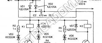
Operation of the circuit. When you clap your hands or click, the carbon powder in the microphone moves and changes its resistance. In this case, at the connection point between the limiting resistor R1 and the microphone, an alternating component appears, which, through the separating capacitor C 1, is supplied to the base of transistor T 1. Transistor T1 is both an amplifier of alternating and direct voltage. With the help of resistor R2, transistor T1 is in a slightly open state. The variable component received at the base is amplified by a transistor and, from the collector through capacitor C2, goes to a doubler rectifier assembled on elements DD1, DD2, C3. Double the constant voltage accumulates on capacitor C3, which is discharged through the circuit: minus the capacitor, resistor R1, base-emitter T1, plus the capacitor. In this case, the transistor opens like an avalanche, relay P1 is activated, its contacts close for the duration of the sound signal. When setting up the operation of the circuit, sometimes it turns out that its sensitivity is too high; it is triggered by cars passing along the street or by waving a hand near the microphone. It all depends on the type of relay used. You can roughen the circuit by connecting a variable resistor in series with capacitor C1. In order to switch the load (light bulbs) using claps, it is necessary to add a trigger to the circuit. The circuit of such a trigger on a polarized relay is shown in Figure 2 - it has not been published anywhere before.
When a sound signal is given (clap, click), the contacts of relay KP1 are temporarily closed. An alternating voltage of 220 V through the lamp L1, diode D1 with a positive half-cycle is applied to the end of the second winding of the RP-4 relay, pin 8, the beginning of the winding, pin 7, current limiter resistor R1, capacitor C1, closed contacts of the relay KR1, pin 220V. The charging current of capacitor C1 switches the relay armature to the left position according to the diagram, light bulb L1 lights up and light bulb L2 goes out, diode D1 is blocked by the relay contacts, and diode D2 is unlocked and ready for operation. When the next sound signal arrives, the contacts of relay P1 KP1 close. A voltage of 220 V through light bulb L2 and diode D2 is applied as a plus to the beginning of the first winding, contact 5, from the output of the winding, contact 6 goes to resistor R1 and recharges capacitor C1. A polarized relay switches the armature to the right contact in the circuit. Diode D2 is blocked, and diode D1 is ready for the next cycle. Light L1 goes out and light L2 lights up. Thus, when sound signals are received, the load switches alternately. In order for the trigger to perform the function of turning on and off only one light bulb, you need to exclude one of the light bulbs from the circuit, and instead turn on a series chain of a 0.33 μF x 300 V capacitor and a 5–10 kOhm, 2 W resistor. When setting up the operation of the trigger, it is necessary to adjust the armature of the polarized relay so that it switches well and is securely fixed in the right or left position.
Correctly determine the beginning and end of the relay windings or change the polarity of one of the diodes. Of course, this design of an acoustic relay on a carbon microphone is more suitable for beginners, so the next article will describe an acoustic relay on a single chip, and a piezoelectric element is used as a sensor. Author: Valery Ivanov.
Forum for discussing the material SIMPLE ACOUSTIC RELAY
Source
Voice relay
I offer a simple acoustic machine for switching on various actuators. The essence of the circuit (Fig. 1) is as follows. At a certain level of acoustic noise near the highly sensitive sensor-microphone VM1, the threshold level of which is set by trimming resistor R1, the signal amplified by the operational amplifier DA1 is supplied to the transistor switch VT1-VT2, which supplies power to relay K1. The relay with its contacts (they are not shown in the diagram) closes the load power supply circuit. After the noise stops, the load is turned off.
Fig.1. Schematic diagram of an acoustic machine
This method is used in microdictaphones, which automatically switch to recording mode when there is a sound signal. I use this circuit to automatically turn on the ultrasonic intercom.
This circuit will serve well in a lighting machine. Then it should be supplemented with a final stage with a turn-off delay of 3...4 minutes. If you install such a machine, for example, in the hallway, the light will light up automatically when there is the slightest noise (a door opening or a voice) and go out after a few minutes in complete silence.
In the initial state, both inputs of the DA1 microcircuit are in a state of equilibrium, and a very weak signal, on the order of several millivolts, is received at the base of the transistor VT1, which is insufficient to open the transistor. When sound is applied to the microphone, alternating voltage is supplied to input 2 of the op-amp. The multiply amplified signal from pin 6 of the op-amp, further amplified by transistor VT1, goes to the electronic switch on transistor VT2, which, in turn, switches the actuator - relay K1.
The relay switch-off delay when the sound influence on the microphone disappears depends on the values of C5 and R2. If the delay is not needed, these elements are excluded from the circuit. When a longer turn-off delay is needed, the C5 rating should be increased. With the ratings indicated in the diagram, the turn-off delay when powering the circuit at 12 V will be 1 min ±10%. If the capacitance of capacitor C5 is increased to 2000 μF, the turn-off delay at the same supply voltage will increase to 10 minutes. However, in the latter case, the accuracy of the exposure time is lost and the dependence on the duration of the initial impact of sound vibrations on the microphone increases.
Diode VD1 is used to eliminate bounce of relay K1 contacts. K1 is a low-power relay of type RES10, RES15 for an operating voltage of 9...11 V. To switch powerful load circuits with a high supply voltage, it is necessary to observe safety measures and use a relay with the appropriate permissible current through the contacts. The VM1 microphone is a DEMSh capsule or similar with a winding resistance of 200...250 Ohms and higher. Good results are obtained when using an FEM electret capsule of various modifications as a microphone (previously used as a built-in microphone in cassette tape recorders).
To eliminate interference and other interference, the microphone must be connected to the device with a short shielded cable no more than 20 cm long. When rigidly attaching the device body to other structures (for example, to a vertical wall), you should wrap the microphone capsule with foam rubber and not screw it to the device body, so that interference when various shocks (for example, the slamming of a neighboring door) did not affect the microphone.
As VT2, you can use medium-power silicon transistors KT603, KT630 or their analogues with any letter indices. KT361 with any letter index is suitable as VT1.
A device that is correctly assembled from serviceable parts requires virtually no setup. You only need to use trimming resistor R1 to select the operating threshold of the device.
How to assemble?
To make miracle technology yourself, you need the following skills and knowledge:
- on reading simple electrical circuits;
- experience with a soldering iron;
- ability to understand electrical and radio components;
- practice in the manufacture of printed circuit boards.
The switch will operate at 9 volts . A rectangular battery is suitable as a power source, but it can be replaced with a battery. When using a step-down transformer or DC-DC converter, you can operate from a 220 W network.
Advice
If you don't have the skills or qualifications, it's best not to try to do it yourself. For such people, there is a huge selection of ready-made options.
Parts List
Resistors:
- R1– 10K;
- R2– 1M;
- R3– 22K;
- R5– 2K;
- R6– 1.8K;
- R7– 330 Ohm;
- R8– 1.5K.
Transistors:
- VT1–KT315;
- VT2–RT315;
- V3– 3107 (DC557).
Capacitors:
- C1– 2200 pF;
- C2– 1 µF*10V.
Diode - VD1– 1N.
Miscellaneous:
- M1 - electrical chip;
- HL1 – LED or relay;
- contact block.
Attention
If a relay is used as a load, then resistor R8 must be changed to 2 Ohms.
Printed circuit board
Small size blank, designed for DIP components . Selecting a case will not take much time. The manufacturing process is not easy, it takes more than one hour. There is enough information on this issue on the Internet. Design is carried out in the Spirint-layout 6.0 program. The manufactured board is shown in photo 1.
Treat the paths with tin . It will protect the surface from oxidation.
An example of the produced coating is in photo 2.
Connection rules and specifics
Although limit switches themselves are designed quite simply, they are used in equipment with complex electrical circuits. Consequently, their connection must be carried out by specialists and strictly according to the schematic diagrams, based on the technical features.
Let's look at an example of connecting a simple mechanical switch in a 3D printer. This is necessary in order to set the extreme coordinates for its carriage. The plug-in limit switch has 3 contacts - COM, NO, NC. When the sensor is open, the first and last contacts are at +5V. The second contact (NO) is grounded.
In the diagram, contacts COM (1) and NO (2) are in a closed state, and COM and NC (3) are open. When the printer carriage reaches its extreme position, the COM and NC contacts are connected and it rebounds by 2 mm
The sensor is connected using two wires - red and black. When the device fires, you should hear a typical click. The indicator switch is connected in the same way, but it also has a third wire - green.
Its activation is indicated by a lit LED and a click. Its connectors on the board have designations: for the red wire V (+5 V), for black - G (ground), for green - S (signal).
The same letters indicate the connectors on the optical switch. It will more accurately control the operation of the carriage, but may malfunction in dusty conditions and sunlight. The activation of the optical pair is accompanied by the inclusion of a light-emitting diode and occurs completely silently.
Limit switches are widely used by furniture makers, installing them in wardrobes. Connection is carried out according to the instructions included with each model. The diagram shows the location of the fastening of the plastic structure with the key. For the middle door, it must be installed so that it does not interfere with the correct movement of the other section door along the guides.
The diagrams show the procedure for connecting limit switches for sliding doors in sliding wardrobes (option b) and for swing doors (option a)
If a limit switch is installed for a swing door, it is fixed using self-tapping screws inside the cabinet. When the door is closed, the button presses, opens the circuit and the lighting does not work. When open, the door releases the button and the lighting turns on.
The simplest circuit of an acoustic switch
The simplest effective acoustic switch circuit can be assembled by anyone with the desire and time. Such a switch can be used for various purposes, for example, to turn on and off the lighting in a room using a clap; the same principle of operation and control of any equipment. In general, this acoustic switch is a very useful thing in home use.
This sensor makes it possible to turn on and off power circuits using a clap. Such a device can be used to turn on the light.
It is quite sensitive due to the presence of a double amplifier using low power transistors. It responds well to clap from a distance of five meters from the microphone.
Disadvantages of acoustic sensors
The disadvantages of these sensors stem directly from what they respond to - sound. The selectivity of the microphone is very high and the development of acoustic light switches is progressing, so that modern sensors respond very accurately to a given sound. But in order to produce this sound, you need to know what it is, and this sound will always be a signal to turn it on or off.
The second significant drawback is the sensitivity zone. For a large room, you will have to clap loudly enough, or come closer.
And if you increase the sensitivity, the sensor can respond to similar signals from the next room.
Hidden and outdoor installation methods
The very first thing you have to decide is what type of switch is needed, which can be indoor or outdoor.
In the first case, installation is carried out inside the wall, for which holes of the appropriate size are cut in it. This type of device is used most often, since the wiring is mainly laid in a hidden way.
External switches are used either in wooden houses, in which the wiring is most often done in an open type, or when lighting devices are laid according to a temporary scheme - in this case, in order not to cut the walls, the wires are laid on their surface.
Where is the three switch system used?
Switch equipment with control from three different points ensures practicality. There is no need to walk across the entire room or long corridor to turn on or off the light.
An example of the location of pass-through switches in the bedroom
It is rational to use such a wiring system for a yard or personal plot. We left the house and turned on the light, approached the building and turned it off. We went out, turned it on again, and went to another object.
For example, a room has several beds. The first device will be at the door, the second near one side, the third near the second side of the bed. That is, there is no need to get up and turn off the lights.
Or illumination of the staircase opening, so as not to go up or down in the dark. One switch is installed first at the bottom, the next in the middle, and the third at the end, at the top of the stairs.
It is convenient to use the connection from 3 places in the entrances. On the first floor they turned on the lamp, on the second or third they turned it off. This significantly saves energy.
It is important to install three-point switches in oblong corridors and openings, with several entrances to different rooms. At the beginning of the corridor they turned it on in the middle or at the end they turned it off.
The lamp control circuit is used both in one room and for a large space.
You can use such a lighting system even in walk-through rooms. They turned it on in one room, walked through the room, and turned it off in another room. Convenient and economical.
Connection errors
The main problem during installation is always not taking into account the power of consumers. For most touch-sensitive light switches, the maximum throughput load is limited to 1 kW. In no case should it be exceeded. Most devices of this type do not contain safety elements that block excessive load. Hence their relative fire hazard when the maximum is exceeded.
Another relatively common mistake when installing 220V touch-sensitive light or energy switches is the incorrect connection of the contact groups. For example, it has been noticed more than once that they try to separate the zero of the power supply network with a control device, instead of a phase. Of course, this creates significant problems in its functioning; it becomes simply impossible.
The practical connection of a phase and a COM port for end devices does not make much sense. However, its purpose is different - to communicate with other switches or pass-through switches.
How to connect?
The cotton switch “Ekosvet-X-300-L” in question consists of a block in which the entire circuit is mounted, and two pairs of wires - white and black. The white ones need to be connected to a 220 V electrical network, the black wires are connected to the lighting load.
The lamp receives zero (directly) and phase (through an ordinary household switch) from the distribution box. These two wires are connected to the white wires. You can do this using the old-fashioned twisting method, but it is better to use special self-clamping terminals.
The black wires are connected to the lamp socket itself. That is, with the usual circuit, phase and zero from the supply network would go directly to the lamp socket, and so you also additionally inserted a cotton (or acoustic) light switch into this circuit.
The block itself must be secured to the body of the lighting fixture. The unit has a sensitivity regulator, with which you can set the desired level of cotton. It is most advisable to set the so-called medium level, so that it is not too light, otherwise the switch will start to operate at the slightest tap, and not too strong, so as not to knock off your palms.
The clapper switch is powered through a regular keypad mounted on the wall. If you need to remove a fancy sound device from the circuit, it will be enough to turn off the key switch.
All that remains is to experimentally test the results of your work. When operating correctly, Ecosvet-X-300-L will only respond to clapping of palms. Tap with a hammer, bring a running vacuum cleaner close to the lamp, beat it in a mug with a spoon, turn on a hammer drill, tease with a mobile phone signal. We don’t know what your experiments will show, but there have been cases when cotton switches were triggered by the sound of a working hammer drill or the ringing sound of a metal spoon hitting a mug. This is further confirmation that there are few ideal things in the world; any device, especially in electrical engineering, has, along with advantages, a number of disadvantages (even if completely insignificant).
How it works
The simplest cotton switch has an electronic microphone in its circuit; in addition, an amplifier is installed with it in the form of two transistors connected to each other. These small details amplify any sound entering the microphone several times. Thanks to this, the switch can be activated even with a slight clap.
The amplified sound pulse is supplied to a powerful transistor, a relay coil is connected to its collector, the power circuit of which is connected to the lighting network. That is, the transistor controls this relay, and it, in turn, closes or opens the contacts in the lamp power circuit.
A capacitor is installed in the microphone circuit. You can select its capacity and thereby adjust the sensitivity of the microphone to the supplied sound.
simple acoustic switch circuit
The acoustic switch is designed on the same principle. The scheme works as follows. The sound captured by the microphone is converted into an electrical signal (voltage). The amplification cascade amplifies the voltage, in this form it is supplied to a powerful transistor, and from it to the relay coil. Current begins to flow through the relay, the magnetic core is retracted, thereby closing the power contacts of the relay in the lighting circuit. The light comes on.
Particularly experienced and competent electricians and radio amateurs will be able to assemble such a circuit on their own.
Connection and installation
The device is mounted on a one-key or two-key switch so that it receives power from a 220-volt network. This can be done as follows:
Acoustic switch connection diagram
- A typical light bulb connection diagram looks like this: power to the switch is supplied from the panel through the distribution box. The neutral wire is fed to the light source and connected in parallel to the switch;
- It is necessary to break the power circuit to the key switch and install an acoustic device into the gap. The controller is installed in the lamp body;
- Most often, the switch is equipped with two pairs of wires, white and black. Power is supplied in white, loads are connected in black. It is better to make the connection using terminals or simply a winding. Soldering is not used in such circuits.
Advantages compared to classic ones
The main advantage is the absence of moving elements of a mechanical system driven by human power. As a bonus, the operating principle is based on relays or electronic keys, which gives greater reliability and durability compared to classic options.
The remaining advantages follow from the previous fact. For example, you can make the switch completely sealed, completely removing the impact of the environment on its functionality. It’s not for nothing that all manual control systems with a high IP protection index are built on the basis of touch operating principles. The ease of use is also worthy of mention. To switch the state, just touch, or simply raise your hand to the device.
Schematic diagram
The control element is the M1 electret microphone - almost any microphone, the most common one with two outputs and a built-in amplifier stage. The signal at the output of the electret microphone is too small to control the logic element, so it is first fed to the amplifier stage on transistor VT1. The collector of the transistor is directly connected to the input “C” of trigger D1.
The operation of the acoustic sensor and the device as a whole is highly dependent on the DC mode of this transistor, therefore, to facilitate setup, the base resistor R2 of this stage is made tuning.
When setting up, they set the operating mode of the transistor in such a way that the voltage at its collector is somewhere at the threshold of a logical unit, but is still perceived by the input of the D1 microcircuit as a logical zero. This must be done experimentally so that the sensitivity and stability of the circuit are optimal.
Principle of operation
Attention The clapper switch is necessary for remote control of electrical appliances and lighting sources. The first clap turns the light on, and the second turns it off
A sensitive microphone picks up the sound wave and transmits the impulse to a power amplifier. Then the signal is sent to the base of the switch to connect the transistor to operation, and the PN junction opens. Current begins to flow into the electrical circuit
The first clap turns the light on, and the second turns it off. A sensitive microphone picks up the sound wave and transmits the impulse to a power amplifier. Then the signal is sent to the base of the switch to connect the transistor to operation, and the PN junction opens. Current begins to flow into the electrical circuit.
To put it simply, the supply and interruption of energy occurs due to the reception of sound signals by a microphone. Used in rooms with minimal noise levels.
Options and features
- Standard product. It is connected to a simple electrical circuit in parallel with the light switch of the device and is adjusted to the desired audio range.
- Combination with timer. Electricity is supplied to the circuit for a certain period of time after receiving the command.
- With an intellectual component. A product of complex design is capable of distinguishing incoming signals and activating a specific device.
- For low current systems. It is used in alarms, to activate cameras, microphones, and provide information to security panels.
Important
It is necessary to think about the installation location in advance. When using a mechanical switch, our homemade switch does not participate in the operation.
Electrical diagram
There are many options on the Internet of varying complexity depending on the configuration, but not all of them are functional. Defects appear during manufacturing. The presented electrical circuit has been tested in practice.
Here VD1 is intended to protect transistor VT3. To use a relay, a diode must be installed . If you decide to install a light load, we recommend replacing the diode with a jumper.
Simple acoustic switch
The circuit diagram for this acoustic switch was found on one of the bourgeois sites. After checking, it became clear that the circuit was not working, after some experiments and alteration of the circuit - lo and behold! she earned it! Almost all the values of the components used were changed to make the circuit more accessible to beginner radio amateurs, and this is the end result.
Perhaps this is the simplest circuit that can exist; it uses a minimum number of components that are available to everyone. As a result of the alteration, domestic parts were used, which greatly facilitates the selection. The microphone was taken from a Chinese tape recorder; you can also use domestic ones, such as pine.
The microphone amplifier is assembled on two KT315 transistors, but to increase the sensitivity of the microphone it is advisable to use transistors like KT368 or its imported analogues; in general, transistors are not critical.
The power part of the circuit is a powerful bipolar transistor that controls the load, and in order to control large loads a relay was used (12-24 or 220 volts).
The signal from the microphone is amplified and sent to the base of a powerful key, the transition opens and it is at this moment that the relay is triggered, the microphone reacts to loud sounds (for example, clap), the sensitivity of such a circuit is 4-5 meters. At the second clap, the circuit is automatically switched off, therefore, the supply of current to the load is stopped.
The capacitors are electrolytic, the voltage is not so important, you can use the appropriate capacitors with a voltage of 10, 16, 25, 50 volts. The range of supply voltages is also quite wide - from 3.5 to 14 - 16 volts, current consumption in idle mode (when the circuit is turned off) is almost zero
The circuit can be assembled either on a breadboard or mounted mounted, the part values are not critical and can deviate in one direction or another by 20%, but try not to replace the capacitances of the capacitors used, since the best parameters are obtained with the capacitors indicated on the diagram
The range of supply voltages is also quite wide - from 3.5 to 14 - 16 volts, the current consumption in idle mode (when the circuit is turned off) is practically zero. The circuit can be assembled either on a breadboard or by surface mounting; the values of the parts are not critical and may deviate in one direction or another by 20%, but try not to replace the capacitances of the capacitors used, since the best parameters are obtained with the capacitors indicated on the diagram.
List of radioelements
| Designation | Type | Denomination | Quantity | Note | Shop | My notepad |
| Bipolar transistor | KT315A | 2 | Search in the Otron store | To notepad | ||
| Bipolar transistor | KT818A | 1 | Search in the Otron store | To notepad | ||
| Rectifier diode | 1N4007 | 1 | Search in the Otron store | To notepad | ||
| Electrolytic capacitor | 1 µF | 2 | 10-50V | Search in the Otron store | To notepad | |
| Resistor | 10 kOhm | 2 | Search in the Otron store | To notepad | ||
| Resistor | 3 MOhm | 1 | Search in the Otron store | To notepad | ||
| Resistor | 48 kOhm | 1 | Search in the Otron store | To notepad | ||
| Resistor | 1.8 kOhm | 1 | Search in the Otron store | To notepad | ||
| Resistor | 330 Ohm | 1 | Search in the Otron store | To notepad | ||
| Microphone | Pine | 1 | Search in the Otron store | To notepad | ||
| Rel1 | Relay | 1 | Depends on load | Search in the Otron store | To notepad | |
| Add all |
DIY cotton switch: diagram, video, photo
To increase comfort and simplify everyday routine, people are constantly improving devices and inventing new ones. Today we’ll look at a device for controlling electrical appliances remotely using sound. A homemade cotton machine is useful, for example, for turning on the light in a vestibule or pantry, where for some reason finding the switch in the dark is difficult or inconvenient. Below, for the readers of https://samelectrik.ru, we will tell you in detail how to make a cotton switch with your own hands, what elements need to be prepared and according to what scheme to carry out the assembly.
Assembly diagrams
All cotton or acoustic machines are united by the presence in the circuit of a microphone, which is needed to record sound. The design also provides a trigger or time relay to control the power relay.
In this circuit, operating from a 220V network, the signal from the electret microphone is supplied to transistor VT1 for amplification, then to the resistance matching unit, the emitter follower on transistor VT2. Next, a trigger and a signal comparator are assembled on the TM2 digital chip.
A comparator is necessary to protect the switch from acoustic interference; it cuts off sounds that are too short or long. The signal that has passed through changes the state of the trigger (on or off), and the trigger, in turn, controls the load—an incandescent lamp—through a power transistor and thyristor.
A circuit for assembling a homemade cotton switch with a similar purpose is based on an integrated timer.
To make it easier to study the diagram, we have identified zones on it. A microphone amplifier on a KT3102 transistor, a comparator on a 555 chip, a TM561 trigger and a KT3102 transistor, which controls the power relay.
No less interesting would be the self-assembly of an acoustic relay on an Arduino microcontroller:
To make a cotton machine with your own hands, you need to prepare three boards:
- Arduino Nano;
- sound module;
- power relay board.
You also need a PC, a USB cable, and a 5 Volt power supply. You need to install the Arduino IDE program on your PC to flash the microcontroller firmware.
By copying the text of the sketch (program) and pasting it into the Arduino IDE window, you can immediately flash the controller. By changing some adjustment parameters and rewriting the device, you can fine-tune a homemade sound relay for yourself. As we can see from the diagram, the controller has four wires: two for power, yellow is the wire that goes to control the power relay from pin 13. Green is the control wire from the microphone, connected to the analog input A0 of the controller.
The chip contains 8 analog inputs and 14 digital input/output contacts. For our project, we took A0 and D13, since together with it the LED on the Arduino board lights up.
Arduino sketch for making a sound relay: Sketch
By changing the value of if(analogRead, we set the sensitivity threshold, the maximum value that can be set is 1024. By making changes to the delay line, the execution time of the sketch changes. This sets the readiness time for switching. In addition, a protective threshold is set against interference and false positives. In addition, The microphone sensitivity can be adjusted with a variable control on the board.
To configure and test the circuits, we took an Arduino UNO simulation board. After receiving positive results and testing the program, an article was written.
The video below clearly shows a homemade cotton switch, which we assembled according to the diagram provided:
Video instructions
Several simple ideas for making your own acoustic light switch are shown in the video:
Now you know how to make a cotton switch with your own hands. We hope that the provided assembly options, simple diagrams and video tutorials were useful and interesting for you!
Also read:
samelectrik.ru
Hello everyone, today we are going to talk about the acoustic switch, and although there are many IC circuit diagrams for this on the Internet for beginners, sometimes it is difficult to find the ICs. With transistors this is already easier and simpler, I saw the diagram - it is surprisingly simple: a two-stage signal amplifier from a microphone on a KT315 or take the modern transistors indicated in the diagram. For example 2sc945 with high gain. You can also replace the power bd140 with the domestic KT818. At first I used 2 pieces of bc547, but later, after testing the circuit with bd140, it turned out that it had burned out, then I replaced it with kt818 and everything worked. The acoustic relay is powered by a 15 V battery. Microphone, taken from a Nokia headset. Transistors bc547 and kt818, load - lamp from garlands, resistors are looking for exactly at nominal value. Capacitors are not a problem. I collected everything on cardboard for the experiment.
The light bulb is designed for 6 volts, so it didn’t last long and burned out after two pops. But it is clear that it works...
Let's take a look at the diagram. The photo shows the parts we need.
We draw conclusions after the tests - pros and cons.
Pros: the circuit is simple and does not require configuration, scarce parts not used, simplicity of the circuit, large power range.
Cons: the relay reacts to any loud sounds, especially low frequencies. Low sensitivity, unstable operation at sub-zero temperatures, you need two claps, and sometimes three.
As you can see, there were more disadvantages than positive aspects; on the other hand, the design showed itself to be very good, with its simplicity. Good luck to all beginners in their endeavors and good work of electronic devices!
samodelnie.ru