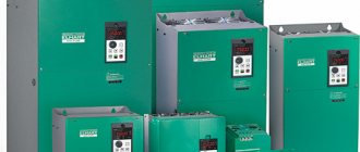
Voltage transformer - designed to reduce the primary voltage to values convenient for measuring instruments and relays, as well as to separate measurement circuits and protection from high voltage primary circuits. Used in AC circuits with a frequency of 50 or 60 Hz with rated voltages from 0.22 to 750 kV.
High voltage transformer (left) and low voltage transformer (right)
Principle of operation
It consists of a steel core composed of electrical steel sheet plates, a primary winding and 1 or 2 secondary windings (the design of a specific device can be found in the manufacturer’s passport or catalog).
As a result of manufacturing, the required accuracy class must be achieved in terms of:
- amplitude,
- corner.
The operating principle of a voltage measuring transformer is no different from a power step-down transformer or a current transformer.
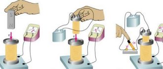
Let us once again describe the operation of the current transformer. An alternating current passes through the primary winding; this current forms a magnetic flux that penetrates the magnetic circuit and the HV and LV windings. If a load is connected to the secondary winding, a current will begin to flow through it, which arises due to the action of EMF (electromotive force). EMF is induced due to the action of magnetic flux. By selecting different numbers of turns of the primary and secondary windings, you can obtain the desired output voltage.
Transformer operating principle
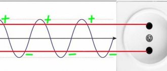
Such devices operate only on alternating voltage. If a constant voltage is applied to the VT, because EMF will not be created by a constant magnetic flux.
Additional Information
Before buying a voltage transformer, you need to analyze all the requirements for the device. It is necessary to take into account not only operating voltages, but also load currents when using a transformer in various devices.
You can make voltage transformers yourself, but if you need a simple household transformer with a voltage of 220 volts and a step down to 12 volts, then it is better to purchase one. You can find out how much voltage transformers cost on any website; as a rule, prices for household step-down voltage transformers are not very high.
From n/a Vladimir Vasiliev
PS Friends, be sure to subscribe to updates! By subscribing, you will receive new materials directly to your email! And by the way, everyone who signs up will receive a useful gift!
Decoding TN
Explanation of markings:
- N - voltage transformer;
- T - three-phase;
- O - single-phase;
- C - dry;
- M - oil;
- K - cascade or with correction;
- A - anti-resonance;
- F - in a porcelain case;
- I — Isolation control;
- L - in a molded epoxy body;
- DE - with a capacitive voltage divider;
- Z - with a grounded primary winding.
Also read: Single-phase cast current transformer - TPOL
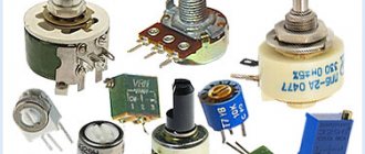
Transformation ratio
Transformation ratio - shows how many times the primary voltage value increases or decreases.
Formula for calculating the transformation ratio
Secondary voltage
Voltage on the secondary winding:
- 100 V,
- 100/√3 V,
- 100/3.
Accuracy classes
Accuracy classes:
- 0,1;
- 0,2;
- 0.5 – used for measurements;
- 1,0;
- 3,0;
- 3P or 6P – designed for protection, control, automation or alarm.
The rated power of transformers for any accuracy class should be selected from the range (VA): 10; 15; 25; thirty; 50; 75; 100; 150; 200; 300; 400; 500; 600; 800; 1000; 1200.
Classification of voltage transformers
TNs are classified according to the following parameters:
- primary winding voltage (3, 6, 10 ... 750 kV)
- voltage of the main secondary winding (100 V - for single-phase, connected between phases, three-phase; 100√3 - single-phase, connected between phase and ground voltage of the additional secondary winding (100V - single-phase in a network with a grounded neutral, 100√3 - single-phase in a network with isolated neutral
- number of phases (single-phase, three-phase)
- number of windings (two-winding, three-winding)
- accuracy class (0.1 0.2 0.5 1 3 3Р 6Р)
- cooling method (dry, oil, gas-filled)
- insulation (air-paper, cast, compound, gas, oil, porcelain)
For voltages of 6 and 10 kV, cast transformer transformers filled with epoxy resin are used. These devices are installed in switchgears. They take up smaller dimensions compared to oil ones. Their advantages also include less maintenance.
Types and classifications
Main classifications of transformers:
- By number of phases.
- Based on the presence or absence of grounding of the output,
- According to the principle of action.
- According to the number of stages of transformation.
- By the presence of a compensation winding or a winding for monitoring network insulation.
- By type of insulation:
- According to design features.
Old 3-phase oil transformer
Installation location:
- outdoor,
- internal,
- built into the power transformer,
- installation as a separate element.
The main features of transformers and their designations are given in the table:
A three-winding transformer should be made with two secondary windings:
- basic,
- additional.
Transformer types
In accordance with their parameters and characteristics, all types of transformers are divided:
- Depending on the number of phases, they can be single- or three-phase
- In accordance with the number of windings, transformers can be two- or three-winding, as well as two- or three-winding with a split winding
- By type of insulation - dry (C) and oil (M) or with non-flammable filling (N)
- By type of cooling - with natural oil cooling (M), with oil cooling and air blast (D), forced circulation of oil cooling (C), dry air-cooled transformers (C). In addition, there are devices without expanders that use a nitrogen blanket to protect them.
Among the various transformer devices, the most common transformers are:
- power
- measuring
- special
Connection diagrams
Connection diagrams for single-phase voltage transformers:
Connection diagrams for three-phase voltage transformers:
Diagrams and groups of connections of windings of three-phase three-winding transformers with main and additional secondary windings
Also read: Purpose of dielectric mats in electrical installations
What is the difference between a current transformer and a voltage transformer?
By definition, these devices are designed to work with different electrical quantities as basic ones and, accordingly, the switching circuits will be different. For example, a current transformer is powered by a current source and does not work, and may even fail, if its windings are not loaded and no electric current flows through them. A voltage transformer is powered by voltage sources and, conversely, cannot operate for a long time at high current loads.
Fire and explosion safety of the device
The explosion safety of the devices is ensured by the design features. The manufacturer indicates the security class in the annotation for the device. Fire ratings may also vary. Modern closed boxes for storing engineering equipment help protect workers and ordinary citizens from injury.
The device must be located indoors and access to it by unauthorized persons is prohibited.
Types and technical characteristics
Depending on the manufacturer, some technical characteristics of the device may vary. This must be taken into account when choosing and purchasing a vehicle.
FMT series
Transformers of the TFM series are intended to power electrical measuring instruments. The active part is placed on a base on which a porcelain tire with an oil volume is placed. Technical data is written on the basis of the device. Popular device TFM-110-II-U1 with four secondary windings. Its mass is 630 kilograms.
TRG series
They are distinguished by a high class of winding accuracy up to 0.2. There is another competitive advantage - you can replace the transformation ratio in the ratio 1:3:4.
Anti-resonance single-phase NAMI series
Single-phase inductive type devices. They are resistant to ferroresonance that occurs when connecting switches.
TBMO series
Large-scale instrument transformers have a maximum service life. They have a high accuracy class. They are distinguished by their miniature size and light weight.
Instrument current transformers voltage class 110
They stand out against the background of foreign analogues with a similar range of actions and durability at minimum rated winding current values.
Devices with non-flammable dielectric
The power of such installations is up to 2500 kVA. Transformers of this type are used in cases where technical conditions do not allow the use of other devices. Most often this is due to environmental conditions and the inadmissibility of open installation of oil transformers.
The use of devices with a non-flammable dielectric has serious limitations due to the high toxicity of sovtol used for cooling. This liquid, having fire and explosion-proof properties, can cause serious harm to the human body and lead to irritation of the nasal and eye mucous membranes.
The main advantage of these devices is the ability to put them into operation without a preliminary audit. During further operation they do not require maintenance or repair.
Types of devices
CTs have design and functional differences from VTs. In their secondary circuit, the current does not depend on the resistance coming from the connected consumer and remains stable throughout the entire time. Only the voltage indicators change. In TN it's the other way around.
Depending on the ratio of turns on the primary and secondary windings, all transformers are divided:
| to bearish ones | raising | dividing |
| W1>W2 | W1 | W1=W2 |
CTs are classified as boosting devices. The number of turns on the secondary winding can be many times greater than the number on the primary. TN - to downgrade.
Types of voltage transformers
NOM 6 -10 are long-lived in this group of devices. Single-phase devices with oil free cooling for 6-10 kV installations. The transformer winding is located in a sealed tank filled with oil. The marking also indicates the year of development and the type of climate control.
Typically, single-phase VTs are connected in pairs according to an open delta circuit. During a phase-to-phase fault, any of the devices remains in operation, so two transformers are sufficient to control the line voltage.
An open triangle connection solves fairly simple problems. In more complex circuits, the problem of voltage asymmetry arises at different load currents across phases. Therefore, in such cases, the VT is connected with a triangle.
ZNOM - grounded transformers. They differ from NOM only in their compact dimensions. They have only one high-voltage terminal with high-grade insulation. The second is connected to ground and is located next to the secondary windings.
NTMI - voltage transformer, three-phase, oil, with a winding for insulation control. Designs of connected single-phase transformers take up too much space. For three-phase networks, it is more convenient to use one VT connected to all phases. Instead of a standard magnetic core, a 5-rod one is installed in it. The 3 central windings of all phases are located. The 2 extreme ones are used for uniform distribution of magnetic fluxes.
The primary windings inside are connected in a star with the obligatory connection of the zero terminal. The secondary windings can be grounded by zero. This is important for the operation of devices that monitor insulation resistance. When they are turned on in good condition without a ground fault, the arrow will stop at the phase voltage indicator, and with a short circuit it will drop to 0. This makes it possible to determine the damaged phase, see the ground fault mode or phase asymmetry and eliminate it using special switches.
TN simplifies the work of operating personnel and helps to identify a blown fuse. In this case, the alarm and control system reacts only in the event of a ground fault and does not notice a phase-to-phase fault or overload.
NAMI is a voltage transformer, anti-resonance, oil, with a winding for insulation control. The phenomenon of ferroresonance is observed when operating voltage transformers with primary windings connected to ground. The occurrence of oscillations leads to the fact that a current many times higher than the rated current passes through the winding. As a result, the transformer fails prematurely due to thermal runaway. The start for ferroresonance is a ground fault. To neutralize vibrations, the design of the device was supplemented with transformers on separate magnetic circuits and resistors were connected to the circuits in a special way.
NAMIT is a similar device intended exclusively for three-phase networks.
NALI is a voltage transformer, anti-resonance, cast, with a winding for insulation control. The phenomenon of ferroresonance is observed when operating voltage transformers with primary windings connected to ground. The occurrence of oscillations leads to the fact that a current many times higher than the rated current passes through the winding. As a result, the transformer fails prematurely due to thermal runaway. The start for ferroresonance is a ground fault. To neutralize vibrations, the design of the device was supplemented with transformers on separate magnetic circuits and resistors were connected to the circuits in a special way.
NOL - voltage transformer, single-phase, cast. These are new generation devices that do not have the disadvantages of oil pumps. The insulating composition does not spill into them, unlike oil-based VTs and is fireproof. It allows you to reduce the dimensions of devices and use them in switchgear without selecting special cells. They can be used in both single-phase and three-phase networks by installing 3 devices nearby.
NOLP - models with a built-in fuse.
ZNOL - grounded cast transformers.
Connection options
Load calculation
The system will work flawlessly only if the load current transformer and all devices are correctly connected to it. To avoid problems, it is important to follow the rules when choosing equipment. One of the key ones: you need to select a model with a suitable conversion factor. Only in this case will the instrument transformers operate normally, and the risk of excessive current values in the network will be eliminated.
You also need to carefully study the instructions for the transformers and meter. Some device models already have built-in protection. They are not intended for transformer connection, and when connected through a transformer, such devices will no longer work normally. If the meter is designed to operate through a CT, then you need to install a suitable type of transformer for current and power values. You can refer to the TT instructions, various reference manuals, where you can obtain the necessary information.
The equipment must meet two conditions:
- Uc.nom = U1nom;
- S2 race < S2 nom.
The rated power of the secondary circuit (S2 rated) must always be less than the rated power (S2 rated).
The U parameter is calculated differently depending on the characteristics of the equipment. If we mean single-phase models that are connected in a star, then to carry out calculations it is necessary to add up the power of all three phases. If a connection diagram in the shape of an open triangle is meant, then in this case the calculation is performed differently - you need to double the power of one transformer.
The secondary load includes the resistance of devices, wires, and contacts.
To determine the resistance of devices, it is necessary to compile a special table. There are already ready-made solutions, but they do not take into account the characteristics of specific equipment. The table includes data on all electrical measuring instruments that are included in the circuit. To calculate the total resistance of the devices, it is necessary to divide the total power consumed by the devices by the rated current of the secondary winding of the transformer.
Calculation of wire resistance when choosing a current transformer for the load is carried out taking into account their length and cross-section, and the contact resistance is determined by the number of connected devices. If there are no more than three, then this parameter is equal to 0.05 Ohm, more than three – 0.1 Ohm. When calculating the resistance of the wires, it is also necessary to take into account that the minimum cross-section for copper is 2.5 mm2, for aluminum - 4 mm2.
The length of the wires is calculated based on the distance between the transformer and the devices, as well as from the connection diagram of the CT and devices. When choosing a current transformer for the load, you need to take into account that it is possible to turn on the device in a full or partial star. The length can be calculated approximately taking into account the characteristics of the object:
- in control panels it is 30–40 m;
- when installing devices in a cabinet - up to 6 m;
- for RU, RU PO - from 45 to 80 m.
With a standard wire cross-section, it may turn out that the secondary resistance in the transformer circuit is higher. In such a situation, it is important to determine what cross-section of wires is required to obtain acceptable resistance in the secondary circuit. When choosing a transformer based on the load, you must not make any mistakes - they can lead to serious consequences.
Formulas for obtaining the required wire cross-section values can be found in specialized reference books - they are widely available. Calculations often result in inaccurate and fractional values that can be rounded up. This is the standard approach for performing such calculations.
Contact connection diagrams
One of the common mistakes when connecting a transformer is incorrect connection of the contacts. This mistake may seem gross, but it is quite common even among fairly experienced craftsmen. You should not rely on experience - it is better to look at the manual once again and check in what order the contacts are located. The manufacturer could have changed them, this is a standard occurrence. The reason for the mistakes of the masters is that they already know everything and do not look at the instructions again.
The meter contains phases and terminals for each phase. In most cases, their values are standard, although it would not hurt to clarify this fact using the manual (instructions). In each phase, the first terminal is designed to connect the power wire and one of the transformer coil wires. The second contact is designed for load. The third contact is needed to connect the second winding. If everything is connected correctly, the system will work as it should.
This connection scheme is called combined, it is used everywhere. However, it has been criticized for being overly biased. Therefore, in practice, craftsmen often use another option - a simpler scheme. In it, the phase wires and the second phase voltage terminal belong to the current contact.
The output of the CT primary winding and the phase input are on one contact. Then it is connected to the load. After this, all that remains is to connect the beginning and end of the secondary winding of the current transformer, the load suitable for the selected network. The beginning is connected to the first contact of the device, and the end to the current winding of the counter mechanism. This connection principle is used for each phase.
It is important to connect and ground the secondary windings of the meter. In this scheme, this is done according to the star principle. Grounding is necessary - it guarantees not only stable operation of the devices, but also safety for personnel. If you use a simplified connection diagram, then instead of 10 wires you can take only 7. This greatly simplifies the process and allows you to avoid mistakes when connecting a large number of contacts.
It is worth recalling once again that when using any circuit, the equipment will work as expected if the current transformer for the load is selected correctly and all the nuances are taken into account. Otherwise, malfunctions and problems with meters cannot be avoided. You can determine that the equipment is selected correctly by the current parameters in the secondary winding. Its minimum value should be at least 5% of the nominal value, and the maximum – no more than 40%.
When connecting the meter through a load current transformer, two types of circuits are used:
- indirect;
- semi-indirect.
When an indirect circuit is used, the meter is connected through CTs (current transformers) and VTs (voltage transformers). This type of connection is common at various industrial facilities; it cannot be found in private homes or offices. Such a connection is required if complex high-voltage equipment is operating at the facility.
The semi-indirect circuit is more common; in it, the meter is connected exclusively through a current transformer. A special counter is used here, which has 10–11 pins. They are divided into three groups to connect three phases. One contact is left for connecting the neutral conductor.
During installation, it is important to follow a number of rules. When installing equipment, jumpers that are used to close current circuits must be closed. But before turning on the devices, the jumpers must be opened. Situations where workers forget to do this are not that rare. The pattern according to which the screws are screwed in and out to short-circuit the circuits in the test box is also important.
Transformer symbols
Each transformer has its own symbols that decipher the main technical characteristics and parameters of the device.
The alphabetic symbols represent the following:
- A – autotransformer design.
- O – single-phase modification.
- T – three-phase device, with or without winding splitting.
According to the cooling system, transformers are marked as follows:
- Dry type: “C” – with natural air cooling, open design; “SZ” – the same thing, protected execution; “SG” – the same thing, hermetically sealed; “SD” – air cooling with blowing.
- Oil cooling: “M” – natural; “MZ” – natural, with a protective nitrogen cushion without an expander; “D” – blowing and natural oil circulation; “DC” – blowing and forced oil circulation; “C” – oil-water cooling and forced oil circulation.
- Using non-flammable liquid dielectric: “N” and “ND” - natural cooling and using blast.
for “What is a voltage transformer”
- Rom
:V
My car, which was imported from Canada, has a 110 V engine heater installed. The heater power is unknown. The wire cross-section is about 0.75 in appearance. I want to buy or make a transformer. If you buy, then their powers are indicated in kVA, what does this mean, please explain, popularly. Or tell me how to do it. What power do you think can be selected?
Answer
- Expert
:
V
Measure the resistance of the heater (with any Ketai multimeter). Its power will be P = U*U/R, P in watts, U in volts, R in ohms. It is better to choose a transformer with approximately one and a half margin, just in case. In addition, the actual power will be less, because When heated, the resistance will increase and the power will decrease. How difficult it is to say, depending on what the heater is made of and how hot it gets. But this can also be written off as a reserve. In the case of a purely resistive load, such as a heater, we can assume that kVA = kW.
Answer
- Rom
:
V
Thanks Expert for the clarification! The resistance was measured earlier - 35 Ohms. P=U*U/R=110*110/35=346 W*1.5 = 519 W. Those. I can take a 0.5 kVA transformer
In what case is kVA not equal to kW?
Answer
- Expert
:
V
In theory, a simple 220/110 transformer is enough. It will be cheaper and safer with it, it provides complete isolation from the network, but an autotransformer does not.
In general, kVA = kW*KM, where KM is the power factor, it ranges from 0 to 1.
For a purely active load (heater, incandescent lamp, etc.), when there is just some kind of linear resistance, KM is close to 1.
But if the load has reactance (inductance, capacitance) or nonlinearity, or even all together, then the KM can be much lower, and then the difference between kVA and kW must be taken into account. kVA is the apparent power, kW is the active power consumed.
Answer
- Admin
:
V
Through an autotransformer, your heater will be galvanically connected to the network; it does not provide isolation. And through the transformer there is complete isolation. If you are absolutely sure that the heater insulation is designed for direct connection to the network and it is in order, you can use an autotransformer. If there is no such confidence, then it is better not to take risks.
Answer
- Volodya K
:
V
In general, kVA = kW*KM, where KM is the power factor, it can range from 0 to 1. For a purely active load (heater, incandescent lamp, etc.), when there is just some kind of linear resistance, KM is close to 1.
But if the load has reactance (inductance, capacitance) or nonlinearity, or even all together, then the KM can be much lower, and then the difference between kVA and kW must be taken into account. kVA is the apparent power, kW is the active power consumed.
Answer
- Elka
:
V
There is not enough brains or knowledge (or both) to understand why some current transformers and voltage transformers, seemingly of the same design, behave completely differently in operation.
Answer
- Denos Fox
:
V
The voltage transformer is powered by voltage. T E the primary winding will have a number of turns and a cross-section in accordance with the voltage. The current transformer is powered by the current generated in the conductor. That is, the primary winding will receive voltage from the current in the conductor. And this current will create a voltage in the primary winding.
Answer
- Elka
:
V
Denos Fox, thanks, but I still don't get it.
The purpose of the current transformer is clear to me - in order to measure a large current, it is necessary to first reduce the current strength to values acceptable for measurement by instruments, so as not to burn these instruments. But how it works is unclear. After all, if the voltage of the secondary winding of a CT reaches several thousand volts, when this winding is short-circuited, a gigantic current should flow through it, which, firstly, should burn the secondary winding with the measuring instruments connected to it, and secondly, lead to a sharp increase current of the primary winding with consumers connected to it.
They tried to explain to me that the current transformer is a step-up trans, so we get less current on the secondary winding, despite the higher voltage. But I still didn't understand the point.
Let's consider two cases:
Design differences between current and voltage transformers
In the first case, we connected the load to the step-down trance winding at a voltage of 220V, in the second, we connected the same load to the step-up trance winding at a voltage of 110,000V. But this does not mean that in the second case less current will flow through the load! Reducing the current with increasing voltage, in theory, only works if the power of the end consumer is constant, as in the very first example from the first post, when we transferred the current through a chain of trans to a consumer connected to a constant (in magnitude) voltage - 220V .
In the second example, we connect the load to different voltages, and the higher this voltage, the greater the current through the load will be, while the current in the lower voltage winding will still be greater than the current in the higher voltage winding. So why, in the case of a current transformer, does increasing the voltage on the secondary winding, to which the measuring instruments are connected, lead to a decrease in the current in it?
Answer
- Vovan
:
V
In a current transformer, the primary winding current does not depend on the secondary current.
Answer
- Petrovich
:
V
Will a 110V transformer withstand 220V? Those. at the output will we get double the voltage or will the primary winding just burn out?
Answer
- Vector
:
V
and if you apply 220 to the primary through a diode (it seems like just half will remain)
Answer
- Lech
:
V
Try turning on the Ilyich light bulb at 220 and see the result. Those who like assholes get it, they bring it, and then... Damn it, it's extreme.
Answer
- Sava
:
V
I just tried to connect 220 V to the primary trans (220 V) through a diode, like 1 half-wave (the LN through the diode burns at full intensity, that’s for sure) and the transformer, whether with or without a diode, produces the same number of volts. The output sine wave is approximately the same, not cut (tried with and without load)
Answer
- Gray P
:
V
But what are the real differences between the windings of transformers for different voltages - do they change the thickness of the varnish coating? If you measure the insulation resistance with a megohmmeter, this can show how much the transformer is designed for? For example, if you find a transformer without labels, how can you find out how much it is designed for?
Answer
Power transformers
The term “power” defines the purpose associated with the transformation of high powers. This is due to the fact that most household and industrial consumers of electrical networks require power supply voltage of 380/220 volts. However, delivering it over long distances is associated with huge energy losses, which are reduced through the use of high-voltage lines.
High-voltage overhead power lines are connected into a single substation network with power transformers of the appropriate class.
Power transformer 110 kV
And along other lines, a voltage of 6 or 10 kV is supplied to power transformers, providing 380/220 volt power to residential complexes and industrial enterprises.
Power mast transformer 10 to 0.4 kV
Oil transformers
This type of transformers is considered the most economical. They are best suited for outdoor installation. Indoors they can be installed at the ground floor level, in special chambers with two external doors.
The operation of oil transformers has specific features. They must be equipped with oil receiving devices in the form of pits or pits capable of collecting approximately 20-30% of the total amount of oil poured into the transformer. The depth of such pits must be at least 1 m. It should be remembered that oil installations are prohibited from being placed in basements and on the second floors of buildings.
Special types of transformers
This group includes:
- dividing
- coordinating
- high frequency
- welding and other types of transformer devices designed to perform special electrical tasks
Isolation transformers
Placing two windings of exactly the same design on a common magnetic circuit allows us to obtain the same output voltage from 220 volts 50 hertz at the input.
This begs the question: why make such a transformation? The answer is simple: to ensure electrical safety.
Where is the equipment installed?
The equipment is intended for outdoor installation. Since transformers are a relatively unsafe type of device, they are placed at a certain distance from residential buildings, schools, and medical institutions. Related measures are required, including:
- installation of a foundation, while allowing the production of a prefabricated oil pit (necessary for emergencies);
- preparing the site for transformer installation;
- preparing travel routes - checking the tools that will be used for loading and mounting;
- preparing oil storage tanks, checking dryers and other additional components.
After checking at idle speed, the vehicle is permanently connected to the power source. The equipment is regularly inspected, including checking all components, a seal is placed and the date of the last inspection is indicated.
Purpose and principle of operation
A voltage transformer converts the operating potential using the principle of electromagnetic induction.
The main purpose of voltage transformers is to convert the input signal to the level required by the user's tasks - when the operating potential needs to be lowered or increased. This can be achieved through the principle of electromagnetic induction, formulated as a law by scientists Faraday and Maxwell. According to it, in any loop located close to another similar turn of wire, an EMF is induced with current, proportional to the flux of magnetic induction penetrating them. The magnitude of this induction in the secondary winding of the transformer (consisting of many such turns) depends on the current strength in the primary circuit and on the number of turns in both coils.
The current in the secondary winding of the transformer and the voltage on the load connected to it are determined only by the ratio of the number of turns in both coils. The law of electromagnetic induction allows you to correctly calculate the parameters of a device that transmits power from input to output with the desired ratio of effective currents and voltages.
A little more about the specifics of some species ↑
The types of transformer voltage directly affect the type of device used. If we are talking about voltages up to 6 kV, then dry type transformers are used, in other cases it is necessary to use oil models.
Internal transforming devices can operate in the range from -40 to + 45 degrees with air humidity of no more than 80 percent. Single-phase internal transformers have cast insulation and differ from oil-based analogues in their lighter weight, more modest size and ease of operation.
Features and differences between oil and dry transformers ↑
Let us remind you that oil transformers are insulated and cooled using an oil composition.
The structure of an oil transformer is a magnetic circuit combined with windings, a tank and a cover. The main element - the magnetic circuit - is assembled from separate steel sheets, well insulated to avoid losses.
The material for the windings is bare wire, usually made of copper or aluminum of various sections. To regulate the voltage, the existing winding is supplemented with branches connected to a toggle switch or switch.
Each transformer of this type has two main types of switching: they can be adjusted under load while the device is connected, and also without load when it is disconnected. The second method is considered the most popular - it is much simpler and safer.
Oil transformers can also be produced sealed. In this case, the oil itself does not come into contact with the air, which means it oxidizes more slowly and gains moisture. Devices of this type are completely filled with a special oil liquid and therefore do not have an expansion tank. As for compensation for expansion due to heating and contraction when temperature decreases, this function is performed by the corrugations of the walls of the tank itself. Another advantage is their improved insulation, since oil filling occurs under vacuum.
The second type is dry transformers, in which air plays the role of cooling. They also represent a connection of a magnetic core and two or three windings, which are placed in a protective compartment. Since air is a much less ideal cooling medium than viscous oil, in such devices the insulation gaps, as well as the channels intended for ventilation, are made larger.
The insulation in the dry version is glass material of high heat resistance class and silicone varnishes that prevent the winding from interacting with moisture. By the way, this makes them much more fireproof than the oil version. These installations can be safely used in any premises, including residential premises.
Where dry-type transformers really fall short is in size. They are more bulky and also have less ability to withstand overloads.
Engineering has all the necessary tools for high-quality maintenance of transformer substations, a well-coordinated team of professionals and licenses that give the right to carry out all the necessary tests and measurements. By choosing the ProfEnergia electrical laboratory, you are choosing reliable and high-quality operation of your equipment!
If you want to order service for transformer substations or ask a question, call: +7 (495) 181-50-34.
Diversity and specialization ↑
Of course, devices of each type and type are used strictly for their intended purpose or within the existing tolerances. Any use of transformers in conditions not intended for their operation is fraught not only with damage to the device itself, but also with very sad consequences for the entire circuit. In order to avoid the possible consequences of incorrect and inappropriate use of transformers, you should carefully read the product data sheet or instructions, as well as existing GOST standards.