Changes in grounding parameters over time
The need to periodically check ground resistance is caused by changes in its actual value over time and depending on climatic conditions.
The latter circumstance is associated with their dependence on many factors, the main of which are:
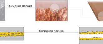
- Deterioration of contact in the areas where metal elements meet due to increased humidity.
- Changes in the condition of the soil at the site of its arrangement on dry and hot days.
- Aging (wear) of metal structures and supply conductors, which, according to GOST, must have a certain thickness.
Grounding resistance checked in any way permitted by regulations using measuring instruments suitable for these purposes. Let's look at the most famous of these techniques in more detail.
Methods for measuring parameters of grounding devices
There are several known methods, using which it is possible to check the presence and measure the resistance of the ground electrode with fairly high accuracy. Let's look at each of these approaches in more detail.
Application of a multimeter
The question of how to measure ground resistance with a multimeter is not entirely correct. This can only be done with professional measuring equipment.
The procedure for measuring ground resistance with a multimeter usually comes down to a simple check of the connection of the ground contact of the socket to the protective circuit. How this can be checked using a tester and an iron, for example, has already been discussed in the corresponding article. Thus, when considering the issue of measuring grounding with a multimeter, this procedure is understood as checking its presence. In addition, this device can be useful for identifying hidden breaks in circuits or lost contacts.
Ammeter-voltmeter method
When applying this method of checking grounding resistance, you will need to assemble a chain, one of the components of which will be the grounding device being tested. It additionally includes a special current electrode, called “auxiliary”.
In addition, this circuit provides another one - a potential electrode (probe), designed to take readings of the voltage drop. It must be installed at approximately equal distances from both the current electrode and the grounded point. Due to this location, it is in an area with almost zero potential (photo below).
Ammeter-voltmeter method for measuring ground resistance
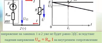
According to this scheme, measurements of grounding resistance are reduced to taking readings of voltage and current and to the subsequent calculation of the desired value according to Ohm’s law R=U/I . This testing method is optimally suited for country and private homes. To obtain the required current in the measuring circuit, you can use any transformer device suitable for power. As an option, some models of welding units are suitable.
Use of specialized devices
As already noted, it is not possible to measure grounding resistance with a simple tester (it is not capable of actually showing how many Ohms the grounding resistance is). This also applies to the circuit with a probe and a current electrode discussed above. To work with them, special analog devices of the following types must be used:
- F4103-M1
- Satellite-2016
- M-416 (multifunction meter)
- IS-10 (microprocessor meter)
- IS-20/1 (more advanced device)
- MRU-101 (professional device
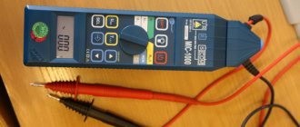
For example, you can see how grounding resistance is measured using the M-416 device. When working with it, you must proceed according to the following plan:
- First, you should make sure that there are batteries in the device compartment (3 pieces of 1.5 Volts each, giving a total supply voltage of 4.5 Volts).
- Then the device prepared for use must be positioned strictly horizontally and calibrated.
- To do this, set the handle with the pointer to the “control” position and, holding the red button firmly pressed, set the pointer to “zero”.
Measurements of protective grounding resistance with this device are carried out according to the same scheme with two electrodes.
Connection diagram for the M-416 device
After the stakes are driven into the ground, wires are connected to them according to the diagram shown (device contacts 1, 2, 3 and 4). Then the indicator of the instrument switch “Range” is set to “x1” (photo below).
Installing the handle of the M-416 device in position x1
Then you should press the control button and turn the “Reochord” knob until the arrow on the indicator shows “zero”. The number indicated on the slider scale must be multiplied by the selected range, which will result in the measured value.
Please note: In a situation where the meter reading exceeds 10 ohms, the multiplier switch (range) should be set to a higher value: “X5”, “X20” or “X100”, and then repeat all the previously described operations. The amount of resistance in this case is determined by multiplying the Reochord reading by a new scale.
To carry out measurements using this method, more “advanced” digital instruments can be used, which are characterized by ease of measurement and maximum accuracy. With their help, you can not only take readings, but also save measurement data in the internal memory.
When carrying out checks using a megohmmeter, you must act according to the instructions (it is similar to the procedures described above for the M-416). However, before checking the grounding resistance with a megohmmeter, you should know that the error in taking readings in this case will be much higher. This fact is explained by the noticeable difference between the systems under study and the usual insulation resistance. This device is more suitable for checking the insulation resistance of electrical networks of grounded equipment, the reliability of which also affects the safety of its operation.
If the insulation is broken, an unpleasant effect can be observed, which is explained by the fact that the resistance of the human body is large enough for a dangerous potential to appear on it. If you accidentally touch a bare conductor, a current will flow through your body, the magnitude of which is sufficient to cause serious injury.
Current clamp measurement
The peculiarity of the method of measuring ground resistance using standard clamp meters is as follows:
- In this case, there is no need to disconnect the grounding device from the equipment being serviced.
- Auxiliary electrodes are also not needed in this situation.
- It becomes possible to quickly control the entire process of taking readings.
The principle of measuring with current clamps is as follows: the test current flowing through the grounding conductor or bus (which in this case is the secondary winding) is assessed by the current clamps by its magnitude. After this, a reading of the voltage acting in the circuit is taken using a voltmeter.
To calculate the desired resistance, you will need to divide the resulting voltage value in volts by the current value in amperes measured using clamps.
Memory composition
Before checking the grounding resistance, remember that a classic charger consists of the following required elements:
- Copper flexible conductors with lugs for standard bolted joints;
Note! In particularly critical places, such connections are made only for welding.
- Thick copper busbars laid in the ground or along the walls of buildings from electrical panels to a ground electrode submerged in the ground (the features of its arrangement will be discussed a little later);
- Finally, the ground electrode itself, which is a structure made from pre-formed steel blanks (rods, channels, etc.).
The design of the grounding loop (also known as a grounding conductor with a set of copper busbars) can have a variety of designs, determined by the protection requirements of a particular facility. The simplest version of this device may look like it is shown in the figure below.
The simplest ground loop
Such a structure is usually buried in the ground near an object grounded with its help (station equipment or a private residential building). During operation, constant monitoring of its condition is carried out, consisting, among other things, of measuring conductivity.
The frequency of resistance measurements is determined by safety considerations for the technical operation of the device, and the period for their implementation is established by current regulations.
Contact resistance measurements
When measuring ground loop parameters, special attention is paid to the so-called “transition” zones formed over the entire area of direct joints of structural elements (including their contact with the soil and the soil itself). For these sections, the concept of “transition resistance” is introduced, which significantly affects the total value. All the measurement methods discussed above also concerned this part of the total system resistance (with the exception of the resistance of the material of the grounding conductors and pins).
By its magnitude, one can judge the speed at which a dangerous charge flows into the ground, as well as the obstacles encountered along the way. In existing systems, this component makes a significant contribution to the formation of the overall indicator for the entire ZK.
How to measure contact resistance
Before measuring grounding in transition zones, you will need to prepare a special device called a milliohmmeter. To carry out these tests, any other grounding measuring device from the same series will do (sometimes M-416 universal devices are used for this). Regardless of the type of device selected, only certified measuring equipment that has passed state verification should be used for these purposes. Otherwise, the measurements taken on the device will not be considered to comply with current standards and GOSTs.
When carrying out such measurements, the device selected as a measuring device with a charged power battery is connected with its clamp terminals on both sides of the controlled connection. Regardless of the type of circuit elements, the transition resistance between them should not exceed 0.05 Ohm. If a measurement of the grounding transient resistance carried out using this method gives an unsatisfactory result, the operation of the installation is stopped until the causes are identified and eliminated. The transient conductivity measurement diagram is shown in the photo below.
Contact resistance measurement circuit
Before checking the ground loop, you need to familiarize yourself with the existing methods for calculating it. In the vast majority of cases, they come down to simple calculations using Ohm’s law (by dividing the measured voltage by the current readings taken in the corresponding circuit).
Additional information: Before calculating the grounding resistivity, it is important to take into account all links in the emergency current flow chain, including contact zones.
The resulting result fully characterizes the design for its compliance with the standardized indicators.
How often is it measured?
The timing of checking the grounding of electrical installations is established in accordance with the following regulatory requirements:
- Visual inspections – every six months.
- Checking the quality of connections of metal elements at their joints - once a year.
Unscheduled checks of the contact resistance of the ground electrode are also possible, which are usually carried out after restoration of the circuit, as well as when serious adjustments are made to its design. Tests can also be carried out when a newly launched grounding system is put into operation.
When organizing regular or extraordinary inspections, it is necessary to be guided by the general provisions for calculating grounding resistivity.
Test object
Testing actions are carried out in relation to grounding devices made as single electrodes or circuits. The objects of inspection do not include PEN conductors and PE conductors included as separate cores in cables.
Grounding devices are created in one of two designs:
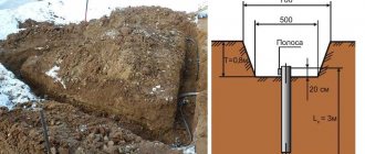
- Horizontal. In this case, the strips are located along the bottom of the trench.
- Vertical. The ground loop consists of strips or pipes driven into the ground and interconnected. The rods are placed in the ground at a depth exceeding the length of the metal products themselves. Most often, the shape of the contour is created in the form of a triangle.
Replacement of system elements is carried out when more than 50% of the surface is rusted. Corrosion testing on electrical installations is carried out selectively where its manifestations are most noticeable. When carrying out verification activities, the grounding of the neutrals is tested. On high-rise lines, at least 2% of the existing supports are checked. The preferred objects of inspection are grounding areas located in the most aggressive environments.
The table below shows the indicators Rз inherent in different types of grounding conductors.
Re-grounding resistance
Re-grounding is a critical element of a comprehensive electric shock protection system. It is installed on the receiving side of the supply line if there is a PE or PEN neutral wire in the connection.
Important! This requirement is valid for networks operating according to a TN scheme with a solidly grounded neutral.
As a rule, both natural and artificially created elements are used as re-grounding. However, the resistance of natural ground electrodes depends on many factors (including climatic conditions), so that over time it constantly changes its value.
In this regard, when arranging this type of grounding, preference is given to artificially created systems that have very specific indicators.
Re-grounding the cottage
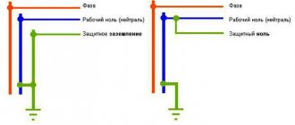
The grounding wire of such a device is led out from the grounding loop towards the input panel with the main grounding bus installed in it.
The need for do-it-yourself re-grounding installed on the consumer side is explained by the following reasons:
- Its presence eliminates dangerous situations that arise in the power supply network when the neutral or grounding wire coming from the power substation breaks (photo above).
- In this case, it can work as an independent grounding, ensuring safe operating conditions for electrical installations on the consumer side.
- With it, in an apartment or private house, you can install electrical wiring with a third (grounding) conductor.
The presence of re-grounding is specifically stipulated in the PUE, certain provisions of which prescribe its mandatory installation and testing.
Features of checking in an apartment and a private house
The technology for testing grounding for a house and an apartment has several differences.
Testing in an apartment
It is necessary to ground all metal objects - radiators, bathtubs, household appliances. It is also worth protecting the sockets and clarifying whether the third contact is included in the circuit. There are several techniques.
Screwdriver + tester + insulated wire
A wire with probes at both ends is used. They work like this:
- Check the voltage in the outlet using a tester, a table lamp, or a smartphone charger. The plug is inserted into the socket very carefully.
- The working socket is turned off through the RCD of the panel, switching the machine.
- Remove the cover from the socket and inspect the connection of the grounding contact. It is connected to a separate cable or grounded to terminals.
- The socket is assembled and the RCD is turned on.
- If there is grounding, check with a tester or an indicator screwdriver. The contact should not overlap the phase.
- They check the grounding of the wire - find a phase, remove your finger from it and place the probe on the sensor. It shouldn't burn.
The serviceability of the “earth” is indicated by the lighting or increased brightness of the indicator.
Thorough check with a long wire
You will need an indicator screwdriver, a tester and a long probe. The work algorithm is as follows:
- Open the electrical panel, use an indicator screwdriver to inspect the yellow-green wire to see if there is no voltage in the ground loop.
- Find the “zero” (blue wire) and attach the conductor probe to it. The other probe touches the yellow-green wire. By the operation of the machine, you can judge the serviceability of the wire.
- Return the RCD handle to cocking. One end of the wire remains at zero, the other touches all sockets and metal products in the room. If the circuit is working properly, the machine operates.
- The bathroom is being checked. A SUP box with a metal bus and wires is located 50 cm from the floor. There should be no tension here.
After checking the voltage in the bathroom, you need to tighten the connections of all bolts.
Check in a private home
The measurement technique for a private house has significant differences from work in an apartment.
Testing the health of soil and metal bonds
Activities involve visual inspection and the use of special instruments:
- For visual inspection, you need to hit the contacts with a hammer with an insulated handle. The conductor should rattle.
- Checking the resistance of metal components with an ohmmeter or multimeter. The acceptable result limit is 0.05 Ohm.
- Grounding terminal in another area if the measurements differ from the standard ones.
Check the soil and metal connections in summer or spring - there is less rainfall at this time.
Checking without a tester and voltmeter
Using a light bulb and a socket with two wires, you can determine the presence of grounding in the country:
- Strip the ends of the wire from insulation and insert it into the socket - the light will light up.
- Correctly measure the grounding with a probe: take out one of the wires and touch the grounding point. If the lamp does not light up, the wire is removed from another hole.
- If the RCD has tripped, the grounding is good.
- Look at the glow of the lamp. When connecting phase and ground, it is brighter than when connecting phase and zero.
Using indicators for European sockets, you can detect all connection flaws.
What is the frequency of measurements?
Before measuring the grounding resistance in one way or another, it is important to take into account the requirements of the PUE regarding the frequency of these tests. According to the main provisions of this document, they can be carried out in the following forms:
- routine examinations;
- extraordinary inspections;
- launch tests.
The frequency of each of these types of inspections is determined by the goals that they set for themselves. The frequency of inspections of the insulation resistance of station equipment is usually consistent with the inspection of the circuit breaker itself. Let's look at their different types in more detail.
Scheduled checks
The timing of planned activities is stipulated by instruction RD-34.22.121-87, as well as the requirements of the PUE. From these documents you can find out what is the frequency of visual inspection of visible parts of grounding devices, which according to them is organized at least once every six months. In addition, from the same standards it follows that at least once every 12 years, inspections of the structure must be carried out with the opening of the soil around it. Measurement of the resistance of grounding loops according to the same documents should be carried out at least once every 6 years.
Persons authorized to do so by the relevant authorities are responsible for conducting such inspections. The owner of a private house must fill out an application for them in advance with subsequent payment. Upon completion of the tests, he is obliged to provide the local energy service with a protocol for measuring the contact resistance between the elements of the closed circuit.
Extraordinary
Extraordinary measurements of circuit parameters should be carried out in the following emergency situations:
- After making changes to the design that are not provided for by the design, but affect the resistance to current flow (measurement of grounding in a private house should be carried out when moving it to another place).
- After emergency destruction and subsequent restoration of the ZK.
- Upon completion of the repair work.
The frequency of their holding is not regulated for obvious reasons.
Starting or introductory
Start-up or introductory grounding checks and resistance measurements are organized immediately after the installation of the protective circuit is completed (that is, on the eve of its delivery to the local energy service representative). To do this, you will need to invite a specialist from an electrical laboratory or other organization licensed to conduct such tests.
Based on the results of the inspection, an acceptance certificate is issued, which is the basis for the subsequent commissioning of the device and confirmation that all supply lines in private houses are grounded.
Test conditions
When organizing grounding testing activities, it is important to pay attention to the conditions in which they are supposed to be carried out. They must be taken into account at the test preparation stage, and upon completion they must be entered in a special journal. According to the requirements of current regulations (PUE, in particular), for this it is advisable to choose the summer season with sunny, dry weather, which allows you to obtain results that are closest to reality. This is explained by the fact that at such a time the soil is maintained in a fairly dry condition, corresponding to the actual operating conditions of the protective structure.
When carrying out control measurements of permissible resistances in damp autumn weather, for example, the results obtained will be significantly distorted. This is explained by the fact that soil saturated with moisture significantly increases the conductivity of the soil. In order to avoid all these difficulties and get a value close to the real value, the easiest way is to use the services of professionals. To do this, you must contact a special electrical laboratory that has a license to carry out the relevant work.
Upon arrival at the site, specialists will identify all factors and organize testing of protective equipment in accordance with the requirements of current regulations. Upon completion of the entire test cycle, they will also draw up a grounding resistance measurement protocol, a sample of which is presented below.
Protocol for testing grounding resistance
It is better to use a megohmmeter to assess other safety factors
For example, insulation resistance. We are not talking about direct danger. That is, if you grab a wire with your hand in which the dielectric properties of the insulation are normal, you will not receive an electric shock.
But there is an additional danger: insulation breakdown under load. This unpleasant fact leads to malfunctions and, what’s more scary, to electrical circuit fires.
A megohmmeter for measuring insulation resistance is a voltage generator and a precision instrument in one housing.
The classic version (still used successfully today) produces voltage up to 2500 volts. Don't be afraid, the currents during operation are negligible. But you only need to hold on to the insulated handles of the measuring cables.
The high voltage potential easily reveals flaws in the insulation, and the meter needle shows the true resistance. Before starting work, you should turn off all voltage-supplying circuit breakers and get rid of residual potential: ground the wire.
To measure the breakdown between wires in one cable, two wires are used. They are connected to the cores of the disconnected cable, and measurements are taken. If the resistance is below normal, the cable is rejected. No one knows when a potential breakdown site will cause trouble.
To measure earth leakage, one wire is connected to the protective ground (in the area where the cable under test is laid), and the second to the central core. The voltage for testing should be higher. If the wire cannot be connected to ground, the measurement is carried out by applying a second electrode to the outer surface of the insulation.
If there is a screen (cable armor), a three-wire measurement system is used. the third wire is connected to the shield of the cable being tested.
The general scheme is exactly this, but each model of the device has its own instructions. Modern megohmmeters with a digital display are even easier to understand than the old pointer meters.
Using a megohmmeter, you can also test motor windings. But this is a separate topic. Information for those who think that all these devices are narrow-profile: using a shunt system, you can turn a megaohmmeter into a precision ohmmeter or voltmeter.
Results
To summarize everything described in the previous chapters, it is necessary to note the following main points:
- Systematic checks of grounding loops make sure they are fully operational.
- When solving the problem of which instrument should be used to take readings, preference is given to special multifunctional devices that provide high measurement accuracy.
- In the process of carrying them out, it is important to adhere to generally accepted methods for determining the exact values of the measured quantities.
- The complete formula for determining the total resistance of the entire grounding structure can be found in the relevant sections of the PUE.
In addition to the article, we offer video materials for viewing that show how grounding resistance is measured using various multifunctional instruments.
In the final part of the review, we note that for a more detailed understanding of all the issues discussed, you should refer to numerous sources widely represented on the Internet. There you can also find a large number of thematic collections and video reviews that allow you to learn how to check and accurately measure the resistance of grounding structures of various types and classes.
Types of memory
What is insulation resistance measurement and why is it important
When solving the difficult question of how to measure ground loop resistance, you should know that the systems described can be used for a variety of purposes. When familiarizing yourself with their design, it is necessary to take into account the main differences between protective and working grounding, which are as follows:
- By working we mean the grounding of the circuits involved in the transmission of current, in particular, the zero or neutral points of station transformers;
- The concept of protective grounding means an electrically conductive connection with the ground of structural elements that are not at dangerous potential (not current-carrying).
Understanding these differences helps specialists organize the measurement of grounding device resistance using specially developed methods.