Author: Evgeny Zhivoglyadov. Date of publication: January 26, 2016. Category: Automotive equipment.
Cassette tape recorders today can only be found in vintage cars, but modern cars are equipped with more serious systems that act as entire multimedia complexes capable of performing hundreds of different tasks. However, drivers love listening to the radio and watching TV on the road just as much as before. Unfortunately, most inexpensive radios with good functionality stop “catching” radio stations as soon as the car enthusiast leaves the city limits. The sound becomes distorted and jumpy, the image synchronization is disrupted, and noise appears. These signs indicate that the signal has become worse and soon you will have to drive along the highway in complete silence.
It’s worth saying right away that even the most advertised brand will not guarantee you a high-quality radio signal. Therefore, if you like to listen to the radio on the road, then buying a more expensive radio will not help. It is better to purchase a tape recorder with an antenna and supplement it with a special amplifier.
FM antenna amplifier
I propose an antenna amplifier circuit for FM radio receivers. As you know, outside the city, reception of radio stations in the FM range is extremely difficult. The signal level noticeably attenuates if there are any buildings or buildings in the path of the waves. To compensate for signal loss, it is necessary to raise the receiving antenna as high as possible, however, it is not always possible to achieve the desired result. A narrowband antenna amplifier will help to significantly change the situation for the better. This amplifier is equipped with a filter at the input, which allows it to block signals below 60 MHz and above 120 MHz, providing amplification only on the VHF band. Coils L1 and L2 are wound with PEL-2 wire with a diameter of 0.4 mm on a mandrel with a diameter of 4 mm. L1 contains 3.5 turns, L2 – 4.5 turns. The amplifier is powered by a voltage of 9-12 volts, while consuming a current of about 12 mA. Gain 18 dB. The amplifier can be wired in a metal case. Connections from the antenna to the amplifier and from the amplifier to the radio receiver are made with a shielded cable.
Discuss on social networks and microblogs
Radio amateurs are interested in electrical circuits:
Please provide a circuit diagram for a medium-wave antenna amplifier.
Gray, as I understand it, you are talking about the amateur radio range of 1.8 MHz or 160 m. If so, then instead of an amplifier for the mid-wave range, try to calculate, design and use an EH antenna . According to radio amateurs, the efficiency, setup, ease of use and quality of reception and transmission of EH antennas are excellent. Moreover, using special programs, you can calculate an antenna for almost any desired frequency from a given range. An interesting fact is that the EH antenna is used underwater. Materials on EH antennas: Information: theory and practice of using EH antennas. Calculations: program for calculating EH antennas 1, program for calculating EH antennas 2
what the hell is om50 when you can make a regular frame antenna and put it on a higher mast
Assembled and connected... No result!
FM antenna amplifier. Make this amplifier directly on the Antenna and connect it to the receiver with an RK-75 cable.
thank you, the diagram is simple, but the effect amazed me; it amplifies the signal almost 75 km away; only the coils L1-L2 need to be moved apart a little and soldered together in a hinged form
Tell me if I replace KT 368AM with KT 372A, what else needs to be changed, if possible, correct the diagram
KT368A is not rated for noise at a frequency of 100 MHz. The gain at a 120 Ohm collector load is negligible. This “amplifier” will not amplify anything in the FM range.
Simple antenna amplifier | DIY master class
The more I understand the modern element base, the more I am amazed at how easy it is now to make electronic devices that previously could only be dreamed of. For example, the antenna amplifier in question has an operating frequency range from 50 MHz to 4000 MHz. Yes, almost 4 GHz! In the days of my youth, one could simply dream of such an amplifier, but now even a novice radio amateur can assemble such an amplifier on one tiny microcircuit. Moreover, he has no experience working with ultra-high-frequency circuitry. The antenna amplifier presented below is extremely simple to manufacture. It has good gain, low noise and low current consumption. Plus a very wide range of work. Yes, it is also miniature in size, thanks to which it can be embedded anywhere.
Where can I use a universal antenna amplifier?
Yes, almost anywhere in the wide range of 50 MHz - 4000 MHz.
- — As a TV antenna signal amplifier for receiving both digital and analogue channels.
- — As an antenna amplifier for an FM receiver.
- — others
This applies to domestic use, but in the amateur radio field there are much more applications.
Antenna amplifier characteristics
- Operating range: 50 MHz – 4000 MHz.
- Gain: 22.8 dB - 144 MHz, 20.5 dB - 432 MHz, 12.1 dB - 1296 MHz.
- Noise figure: 0.6 dB - 144 MHz, 0.65 dB - 432 MHz, 0.8 dB - 1296 MHz.
- Current consumption is about 25 mA.
More detailed specifications can be found in the SPF5043Z datasheet. The low noise amplifier has proven itself to be excellent. The low current consumption is fully justified. The microcircuit also perfectly withstands high-frequency overloads without loss of characteristics.
Making an antenna amplifier
Scheme
The circuit uses an RFMD SPF5043Z microcircuit, which can be purchased on AliExpress
. In fact, the entire circuit is an amplifier microcircuit and a filter for its power supply.
Amplifier board
The board can be made from foil PCB, even without etching, as I did. We take two-sided foil-coated PCB and cut out a rectangle measuring approximately 15x20 mm.
Then, using a permanent marker, draw the layout along the ruler.
And then you want to etch, or you want to cut out the tracks mechanically.
Next, we tin everything with a soldering iron and solder SMD elements of size 0603. We close the bottom side of the foil board to a common wire, thereby shielding the substrate.
Setup and testing
No adjustment is required; you can, of course, measure the input voltage, which should be within 3.3 V and the current consumption is approximately 25 mA. Also, if you operate in the range above 1 GHz, you may need to match the input circuit by reducing the capacitor to 9 pF. We connect the board to the antenna. The test showed good gain and low noise level.
It will be very good if you place the board in a shielded case, like this.
A board for a ready-made amplifier can be bought on AliExpress
, but it costs several times more than a separate microcircuit. So it’s better to get confused, it seems to me.
Schema addition
To power the circuit, a voltage of 3.3 V is required. This is not entirely convenient, for example, if you use the amplifier in a car with an on-board voltage of 12 V.
For these purposes, you can introduce a stabilizer into the circuit.
Connecting the amplifier to the antenna
In terms of location, the amplifier should be located in close proximity to the antenna. To protect against static and thunderstorms, it is desirable that the antenna be DC-switched, that is, you need to use a loop or frame vibrator. A Biquadrat antenna would be an excellent option.
Watch a video testing a simple antenna amplifier
sdelaysam-svoimirukami.ru
Simple antenna amplifier for VHF(FM) receiver
VHF FM radio has become an indispensable attribute at home, in the car and in the country. And one of the problems that arises during its operation is ensuring the required quality of reception at a great distance from broadcasting stations.
Unfortunately, not all radio receivers have good sensitivity, so when you move several tens of kilometers away from radio stations, for example, while staying in the country or traveling out of town, the quality of reception deteriorates significantly.
Installing effective receiving antennas on a car or portable equipment is very difficult or simply impossible.
A way out of this situation may be to use a low-noise antenna amplifier at the input of the radio receiver. If the radio receiver is multi-band and has one antenna input (for example, a car), then the amplifier must amplify the signals of this particular range and transmit signals from others without loss.
In addition, in city conditions, when the level of radio signals and interference is significant, such an amplifier must be turned off to avoid crosstalk distortion.
If reception is carried out far outside the city, then the amplifier can be made non-switchable.
Radio signal amplifier for car radio: antennas, FM signal, external
A radio signal amplifier for car radio improves reception quality in difficult conditions. This device is used with both radios and televisions.
When do you need an amplifier?
A car antenna amplifier is needed when the signal level is insufficient for comfortable listening to FM radio in the car. This most often occurs in small towns, remote from large radio stations or powerful repeaters.
When receiving on a passive car radio antenna while the vehicle is moving in unfavorable conditions, noises and clicks occur that interfere with listening to music and speech programs. If the car enters an area with an extremely low signal, then the interference is constant, blocking the radio transmission.
What affects the signal level
The level and propagation of the signal in the FM range is affected by:
- uneven terrain;
- high-rise buildings built from reinforced concrete;
- atmospheric phenomena;
- interference sources installed in the machine;
- distance from the transmitter to the car antenna.
What to choose
When choosing an antenna amplifier, you should pay attention to various parameters. This device must have a wide bandwidth and a uniform amplitude-frequency response. Also, a high-quality antenna amplifier has a low signal-to-noise ratio. To ensure stable reception and protection from interference, it is recommended to install the amplifier closer to the antenna. If you install it next to the radio, the level of interference generated by automotive electrical equipment will increase.
The device must be accompanied by instructions and all accompanying documentation. Please note that this device should not be used in conjunction with an active antenna. Because of this, the reception will greatly deteriorate, since the car radio will catch all the on-air garbage. And while tuning the receiver, you will constantly listen to signals from strong stations with distorted and noisy sound.
Domestic manufacturer
Among car radio amplifiers produced in Russia, the most popular device is called “Triad-304 - Long Range”. It improves reception at a distance of 60 to 120 km from the radio station, operates in all required ranges, and has a light indication of the presence of power.
Another feature is a city-highway switch, used to lower or increase sensitivity depending on radio reception conditions.
The connecting cable is long enough so that the radio amplifier can be installed closer to the antenna.
Other advantages include low price, high reliability and sensitivity.
Foreign manufacturer
The most popular foreign antenna amplifier is Prology TFB-100. It differs in that it amplifies both analog and digital radio and TV signals with equal quality.
You can connect several antennas to it, which will improve the quality and stability of the signal at the border of the stable reception zone. This accessory will be useful for those who have a multimedia system with a TV in their car.
How to make it yourself
You can also make an antenna amplifier for a car audio system yourself. This device is built according to the classical scheme. A high-frequency filter is installed at the input, assembled according to a P-circuit and providing an input impedance of 75 Ohms. It consists of a coil connected in series and 2 capacitors with a capacity of 27 pF connected in parallel. To protect audio equipment from accidental high voltage, a low-pass filter using a T-circuit is installed after the high-pass filter.
1 stage, built on a KT 368 AM transistor or its analogue, gives a gain of 15 dB in the FM range. Resistors can be used to more finely tune the characteristics of a radio-electronic device. The positive power is supplied to the collector of the semiconductor, the negative to the emitter.
To stabilize and filter the current, a zener diode D 814 G or its equivalent and a capacitor with a capacity of at least 100 μF are connected parallel to the power input.
The number of stages is determined by the required gain. The connection between them, as well as the car radio input, is capacitive. You can assemble an amplifier for a car radio using either a radio kit or existing parts. A short piece of coaxial cable with a suitable plug is connected to the output of the device. The entire structure is placed in a plastic or tin case of the required size.
How to install and connect
Installing and connecting the amplifier will not cause any particular difficulties. First, you need to remove the plug of the external external car antenna from the radio. The amplifier is then secured in a suitable location. If it is equipped with a city-highway switch, then for ease of control the device is installed on the instrument panel near the radio or in the glove box of the car.
The output plug of the amplifier is inserted into the antenna socket of the radio, and the antenna plug is inserted into the input connector. After this, power is connected to it. To do this, the wire coming from the amplifier is connected to the blue wire with a white stripe of the radio, which carries the power plus.
The negative is supplied to the amplifier through the side contact of the socket and the screen shell of the connecting cable. With a strong signal, the quality of reception on an antenna with an amplifier can be improved by folding the telescopic rod or bending the flexible one. It is worth considering that the receiving dipole should not come into contact with the car body.
autotuning.expert
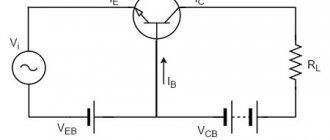
Schematic diagram
The amplifier circuit is shown in Fig. 1. It is made on a low-noise bipolar transistor. The gain is about 20 dB.
Rice. 1. Schematic diagram of an antenna amplifier for VHF receivers.
At the input of the amplifier, a series-connected low-pass filter (LPF) C1L1C2 with a cutoff frequency of 115.120 MHz and a high-pass filter (HPF) with a cutoff frequency of 60-65 MHz are installed.
Thus, the amplifier provides amplification of signals from radio stations operating in both VHF broadcasting bands.
If the amplifier is planned to be placed in a radio receiver that uses one antenna for all bands (car version), then its circuit must be modified and two relays introduced, as well as an additional power filter.
The device diagram of this option is shown in Fig. 2. When the supply voltage is applied, relays K1 and K2 connect amplifier A1 (shown on it) between the antenna and the receiver, and when the power is turned off, the input of the radio receiver is connected directly to the antenna.
If the amplifier will be installed in a car, then it must be placed in a metal case and power must be supplied through a pass-through capacitor (C9).
Rice. 2. Antenna amplifier connection diagram.
Parts and PCB
The amplifier elements are placed on a printed circuit board made of double-sided foil fiberglass; the pattern of the printed tracks and the arrangement of the elements are shown in Fig. 3.
The second side of the printed circuit board is left metallized and is connected along the circuit with the common conductor of the first side. For the automotive version, the printed circuit board should be extended so that a relay and power filter can be placed
In the amplifier, it is desirable to use a low-noise transistor with a normalized noise figure; the KT3120A indicated in the diagram is best suited, as well as KT382A, KT382B, KT399A, KT3101A-2, KT3106A9; it is possible to use the KT368A transistor, but the results may be slightly worse. Capacitors KD, K10-17 and similar imported ones, S9 – K10P 4 K10-51 KTP, B23. Resistors – MLT S2-33, R1-4.
Rice. 3. Printed circuit board for VHF antenna amplifier.
Coils L1 and L2 are wound with PEV-2 0.4 wire on a mandrel with a diameter of 4 mm and contain 3.5 and 4.5 turns, respectively. Coil L3 is wound on a ring with a diameter of 8-10 mm made of ferrite grade 2000NN and contains 20-30 turns of PEV-2 0.2 wire.
The amplifier is connected between the antenna socket and the radio input. In this case, the connection from the amplifier to the receiver input must be made with a short shielded cable.
When installing in a car, all connections should be made with a shielded cable, and the amplifier should be placed near the radio in a shielded compartment.
If the amplifier is switched (car version), then a power switch is needed, which is placed in any convenient place.
The filters are designed to work on a cable with a characteristic impedance of 50 Ohms; when working on a 75 Ohm cable, it is necessary to reduce the capacitance of capacitors C1-C4 and increase the inductance of coils L1 and L2 by one and a half times.
Step-by-step manufacturing instructions
To make an indoor antenna for digital TV from a cable, you need to have the following on hand:
- a piece of coaxial cable 2.5–3 m long;
- knife;
- marker for marking;
- ruler;
- a plug for connecting the finished antenna to a TV or set-top box;
- 5 minutes of free time.
A digital cable antenna is made as follows:
- An indent of 50 mm is made from the end of the cable. In this area, the outer insulation is removed, carefully so as not to damage the braid.
- The braid and foil are folded to the side.
- The internal insulation is cut off and the central core is stripped.
- The braid, foil and core are tightly twisted into one bundle, the tighter the better.
- An indent of 220 mm is made from the end of the stripped insulation and a mark is placed. A 20 mm segment is set aside and a second mark is drawn.
- In the resulting area, the outer protective coating is cut off and the shielding is removed. The internal insulation and the central core must remain intact.
- Another 220 mm is measured from the end of the protected area, a mark is placed and an additional 10 mm is set aside.
- In this area, the operation is repeated: the external insulation is removed. However, here the braid should remain intact.
- The end from which the work began (the one where the core and the braid were twisted together) is carefully and tightly twisted around the 10 mm section where the braid is exposed (it is better to use pliers, but you can also use your hands).
- The result should be a neat ring of cable - this is the antenna.
- An RF plug (male) is attached to the free end of the cable.
However, simply holding the cable ring in your hand with the plane facing the repeater is not very convenient, so you can make a holder from plywood or thick cardboard - a ring of the same diameter on a 4-5 cm long leg.
This is necessary in order to avoid deformation of the resulting flat antenna. It is placed on the ring and secured with glue or electrical tape, the free end of the cable is laid along the leg. It itself is attached to the stand of the design that you come up with.
In addition, if you fill the joint with sealant or hot glue, the result will no longer be an indoor antenna, but an outdoor one.
Setting up
Setting up an amplifier comes down to setting the required DC mode. By selecting resistor R4, the optimal collector current of the transistor is established, at which the noise figure is minimal.
Such modes are usually indicated in the reference book. Then the frequency response of the input filters is checked, and if adjustments are necessary, the turns of the inductors are shifted and moved apart.
An experimental test of the amplifier was carried out in the city of Fatezh at a distance of 40-45 km from the radio broadcasting stations in Kursk. It was installed in a receiver having a VHF band with frequencies of 65.8. 74 MHz.
Reception was carried out using an external antenna. Without an amplifier, reliable reception of two government radio stations was possible, and one commercial radio station was received with poor quality. After installing the amplifier, it became possible to reliably receive six radio stations operating in this range in Kursk.
I. Nechaaev, Kursk, N. Lukyanchikov, Fatezh, Kursk region. R2001, 1.
How a car antenna works
Such a device is necessary to receive electromagnetic waves. It begins to convert the energy flow of these waves into an electrical signal. After these manipulations, this signal can be amplified and converted. Reception of such waves is possible only when the antenna is tuned to the required frequency or frequency range.
In order for it to capture the required frequency range, you need to choose the right length, because The quality of the received signal and sound will depend on this. In order for the device to pick up FM frequencies, the antenna must be at least 750 mm long. This explains the relationship between the size of the device and the quality of the resulting sound.
To make an antenna for a radio with your own hands, you should first decide on the type of mechanism.
There are several types, each of which is used for its own purposes.
For example, an active antenna is an electronic mechanism that combines a radio wave receiver and a radio frequency amplifier. It is capable of processing a weak signal that is sent to the canvas, then to the body of the amplification device, after which it is transmitted via cable to the antenna input of the car radio installed in the vehicle interior. Passive antennas can only receive signals from local stations.
ANTENNA AMPLIFIER FOR CAR RADIO
All car enthusiasts have radios in their cars, but not all radios pick up the radio well. Only expensive devices are equipped with serious receivers with good UHF, capable of receiving weak FM stations. Most cheap car radios only work acceptably in the city, so it makes sense to equip them with an antenna amplifier. There are two options here - buy a ready-made industrial one or solder it yourself.
Antenna amplifier Ratex
For those who have some amateur radio skills, a couple of circuits of such amplifiers are offered.
The input coil L1 consists of four turns of enameled copper wire (frameless) on a mandrel more than 5 mm in diameter. Coil L2 is similar to L1, but has only three turns. The pinout of the 2SC2570 is shown in the diagram.
Amplifier for radio in car – Crafts for cars
Sometimes, due to a low-quality radio receiver on a car radio, you have to buy separate HF amplifiers for normal radio reception. At the same time, the choice of such amplifiers is quite difficult, taking into account the fact that there are now a lot of cheap Chinese products on the market that do not really work.
One day they gave me such an amplifier for repair, or rather, so that I could assemble a normal amplifier in the same case.
I would like to present the design of a cheap FM amplifier for a radio receiver. It turns out that this is not an amplifier at all, but God knows what. The circuit consists of only pairs of transistors, and one of them is simply for illuminating the LED.
Power is supplied from the vehicle's on-board 12 Volt network and... nothing happens, only the LED indicator lights up and that’s it - no other reactions are observed from the car radio, with or without an amplifier - the reception is the same.
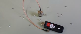
The photo shows the board of such an antenna amplifier, note - I did not repair anything, and did not touch the board at all, but mistakes are visible on the board - a large piece of solder, it is not clear why, an extremely dirty board, oxides everywhere, and generally a non-working, useless thing.
The price of such an amplifier is around 200 rubles; in exchange, for pennies you can assemble an antenna amplifier at home. A couple of working circuits of such amplifiers are presented below
These schemes are very similar to each other, there are very few differences. Both have been tested and are quite workable options, they are clearly more useful than a Chinese trinket, and they also do not contain scarce components.
The entire element base can be found in an old radio or tape recorder. Just one low-power transistor KT368, which can be replaced with any other RF transistor; among imported analogs, SS9018/C9018 is perfect - in theory the same thing.
And I also want to note one point, if you decide to buy a bicycle, for yourself or for your children, then I would like to recommend Pegasus. Excellent value for money, offered to you by the Ultrasport company.
Similar articles:
xn—-7sbgjfsnhxbk7a.xn--p1ai
Second option FM UHF
Together with a good directional antenna, this two-stage antenna amplifier for the VHF FM range will allow you to get clear reception even of distant radio stations. The amplifier will also significantly improve the reception quality of local city FM signals. It is recommended to use imported transistors, as the result is much better with them. Some of them, including the pinout, are shown in the table.
The gain of the second MOSFET is controlled by resistor P1, which sets the bias voltage for T2. For example, if you live near a powerful VHF-FM and TV transmission center, then you understand that high gain will lead to cross-modulation and other unwanted effects in the FM band.
The amplifier is assembled on a double-sided printed circuit board shown in the figure. Coils L1, L2 and L3 are wound on a 4.5 mm frame.
Peculiarities
Do not forget that the signal tends to deteriorate and sometimes disappear completely at night, and also depending on weather conditions. For example, in rain, snow or strong wind. However, it should be noted that if there is a signal, the whip antenna will ensure its high-quality transmission. In addition, not all music centers are capable of improving signal reception with hardware. This problem is especially observed in inexpensive models, where, regardless of which antenna is connected to the system, no changes in the signal reception level are observed.
In rare cases (as an experiment), users try to improve reception by plugging the plug of a regular household TV antenna into the FM socket. Under no circumstances should you do this; it does not always help; most often, problems with short circuits and power surges may arise.
Don't also forget that:
- Reliable reception is possible only when directed towards the signal source.
- In the evening and at night, the signal weakens significantly due to the absence or reduction of long-range reception.
An antenna for any music center can be made with your own hands, the main thing is to carefully follow the instructions and be patient.
Sorry. No data yet.
- https://stroy-podskazka.ru/muzykalnye-centry/fm-antenny/
- https://hitech-online.ru/audio-video-foto/muzykalnyj-tsentr/antenna-svoimi-rukami.html
- https://tehnika.expert/cifrovaya/muzykalnyj-centr/antenna.html
More about coils
FB1, FB2, FB3 = 5 turns of 0.15 mm wire on ferrite beads.
L1 = 7 turns 0.9 mm dia. enameled copper wire; internal diameter 5 mm.
L2, L3 = 7 turns 0.9 mm, winding diameter 5 mm;
L4 = 30 turns of 0.15 mm diameter enameled copper wire on a 1 MΩ resistor with a power of 0.5 W.
In the absence of instruments, tuning can be done by ear - to the maximum quality, using a bad antenna (a small piece of wire).
Amplifier for FM receiver
A simple do-it-yourself HF amplifier for the FM range
To receive remote FM stations, we can recommend a simple RF amplifier circuit using a single transistor.
The common emitter UHF circuit is based on a 2SC2570 transistor.
To obtain a good result, the circuit must be soldered on a high-quality fiberglass printed circuit board. The input/output trimmers (VC1 and VC2) need to be adjusted to the maximum signal.
The input coil L1 consists of four turns, wound with a pitch of 5 mm on a mandrel. with a tap from 1 turn. Coil L2 has three turns, wound with a pitch of 5 mm on a mandrel. The coils are wound with copper wire coated with enamel with a diameter of 0.91 mm.
The pinout of the 2SC2570 transistor is shown in the figure above.
This active FM amplifier is powered by 12V DC. Can be used to boost the signal in a car.
P O P U L A R N O E:
This frequency divider on U813BS (U664B) can be used for a frequency counter. Its frequency range is from 80 to 1000 MHz. Sensitivity is about 10 mV. Read more…
Many people still have “Radiotekhnika U-101-stereo” power amplifiers from Soviet times. The article below discusses its diagram, characteristics and modifications.
MZF with low nonlinear distortions
Main technical characteristics:
- Rated output power at a load of 8 ohms, W ... 25
- Harmonic coefficient, %, no more than ……………….. 0.003
- Output voltage slew rate, V/µs…. at least 40
- Rated input voltage, V……………….. 0.7 More details…
This distributor allows you to simultaneously receive two television programs from one antenna. The main TV is connected to the first output, and the secondary TV is connected to the second. From the second output, the image can also be recorded or shown as an inserted picture. Gain 3.5-7dB. Read more…
– n a v i g a t o r –
SHARE WITH YOUR FRIENDS
your comment
Subscribe RSS
Subscribe to our RSS feed to receive site news. Stay connected!
10 popular articles
- A simple and reliable do-it-yourself metal detector – 199,635 views.
- DIY microwave oven repair – 183,938 views.
- Simple DIY metal detector – 182,587 views.
- Charger from a computer power supply. – 176,360 views.
- Car chargers. Scheme. Principle of operation. – 150,494 views.
- A simple and reliable thermostat circuit for an incubator - 139,166 views.
- DIY moonshine still – 109,486 views.
- How to change the USB connector yourself? – 101,652 views.
- Simple automatic charger - 101,648 views.
- A variety of simple circuits on the NE555 - 93,209 views.
Article Archives
- We are in social networks:
Briefly about the site:
Master Vintik. Everything with your own hands!
– this is a site for those who like to make, repair, and create with their own hands! Here you will find free reference books and programs. The site contains simple diagrams, as well as tips for DIY beginners. Some of the repair schemes and methods were developed by the authors and friends of the site. The rest of the material is taken from open sources and is used for informational purposes only.
Do you like to tinker and make crafts? Send photos and descriptions to our website by email
or through the form.
Programs, diagrams and literature - all FREE!
If you like the site, add it to your favorites (press Ctrl + D)
, and you can also subscribe to RSS news and always receive new articles on the feed. If you have a question about a pattern or craft? Welcome to our forum! We are always happy to provide assistance in setting up circuits, making repairs, and making crafts!
How to determine if the signal is weak
You should install a car antenna amplifier only if the signal level is low. The main features can be called:
- Frequent interference.
- Sound distortion when listening to a radio station.
- Lost image synchronization.
- Periodic complete disappearance of the signal.
For a radio, an amplifier is a device that can increase the signal level. In this case, the transmission quality can be doubled. You can install the device yourself, there are no problems with this.
Reasons for a bad signal
The amplifier for the car antenna is selected taking into account the reason that led to the problem. The main ones can be called:
- Malfunction of the antenna and other elements. High humidity often causes oxide to form, which impairs contact.
- Hissing and wheezing while listening to the radio indicates a malfunction of the receiver itself. In most cases, the problem is a cracked circuit board.
- Additional interference degrades the signal quality in the car. They can be created by mobile operator towers, power plants, and railway tracks.
- Moving away from the signal source also causes a decrease in the quality of reception.
- Additional interference may be created when the recorder is connected to a power source via the cigarette lighter. This problem can be solved by installing equipment that runs on a built-in battery.
In most cases, artificial interference and distance from the source cause signal deterioration. It is recommended to amplify the radio in case of frequent long trips.
Inevitable factors that affect the signal
Note. Note that the best effect is achieved if you connect the amplifier to an external antenna. Thus, an active rather than a passive dipole is connected. Distance is also important. So, you should not count on high-quality reception if the station (main transmitter) is located at a distance of more than 120 km.
It is worth noting that there are side factors that in one way or another affect the signal level:
- In the city itself, signal over-amplification may occur. The manufacturer recommends either turning off the amplifier in a city area or reducing the gain;
- It is also not recommended to use the amplifier simultaneously with an active antenna. This can lead to the opposite effect: the signal will deteriorate and distortion will appear;
- After replacing the head unit, interruptions in signal reception may be noticed. It turns out that the problem may lie in the power supply, which was forgotten or could not be connected to the active antenna. Buying a special adapter or making one will immediately solve the problem.
Amplifier selection criteria
You can choose a suitable antenna amplifier for your car radio by taking into account various recommendations. They are as follows:
- To begin with, pay attention to the fact that the device must be located in close proximity to the antenna.
- The operating band must cover the required frequency range. Due to this, you will be able to listen to all available radio stations.
- The amplitude-frequency response should be as uniform as possible.
- The gain is selected in the range of 15-25 dB.
- Stability of operation must be ensured when the supply voltage varies.
- The dynamic range is selected taking into account the need to protect the device from overload.
- The noise figure is much less than the signal-to-noise ratio.
- It is recommended to give preference to devices from popular brands. They last much longer and have more attractive properties.
The FM frequency, when installed with a suitable amplifier, will be virtually interference-free. However, in some cases there is a possibility that such an element will cause noise at a high signal level.
Best models
There are practically no popular models among amplifiers. Such devices are installed extremely rarely, since a modern multimedia system allows you to play music from various media. When determining a popular model, the following points are taken into account:
- Device cost. A proposal of domestic origin costs 1000 rubles. Do not forget that the price determines the basic properties of the device.
- Length of service life. Installing an amplifier involves changing the receiver connection circuit. Therefore, you should connect a device that can last for several years.
- Reliability. The device must operate under various operating conditions: voltage changes, temperatures, humidity and other situations.
- Signal level. This indicator can vary over a wide range.
There are models of domestic and foreign origin on sale. Models of foreign origin are more popular; domestic ones are several times cheaper.
Triad 304
A domestic car antenna amplifier called “Triad 304” costs 650 rubles. There are various reviews on the Internet, many of them negative. The positive points are the following:
- Low price.
- Good build quality.
- It is possible to turn off the device if the signal is strong.
- Optimal functionality.
Such an amplifier does not last for a long period. Therefore, they often give preference to other models from foreign manufacturers.
Prology TFB-100
An antenna amplifier of foreign origin is more popular due to its attractive performance characteristics. The Prology tfb-100 model has the following features:
- The device can simultaneously operate with several antennas.
- High-quality signal amplification is carried out in the digital and analog range.
The device in question is small in size, so installation does not pose any problems.
Master kit
When looking for a universal version, the Master Kit car antenna amplifier is selected. It has the following features:
- The applied scheme is two-stage.
- There are special kits that are easy to assemble. To do this, it is enough to have a soldering iron and the required consumables.
The cost of such sets is relatively low. Therefore, they are chosen to improve the quality of radio signal reception in various bands.
The most popular amplifier models
But they are not there. Example, “domestic” amplifier “Triad 304”. Such an amp costs about 650 rubles. Let's say right away the reviews about this amplifier are not the best. Judge for yourself what good can be in it if it is empty inside.
Most likely this miracle, registered under a Russian name, was produced wherever you think... And there are plenty of such amplifiers.
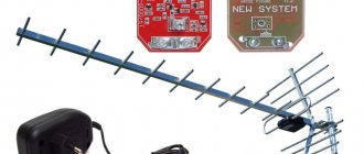
The antenna with a built-in amplifier “Bosch Autofun Pro” received positive reviews.
Only here lies the catch. Here are the photos for you. One antenna is “left” (on the left), and the second is the original (on the right). One doesn’t catch anything, but the second caught perfectly well 100 km away.
How to make it yourself
You can make a radio amplifier for your car radio yourself. Among the features of the work, we note the following points:
- The circuit is represented by a combination of several resistors. They are connected by soldering. When connecting, you need to carefully clean the contact, as otherwise additional resistance may appear.
- Resistors R1, R2, R4, R6 are used to stabilize the changes occurring in transistors VT1. Changes may include voltage and temperature.
- All elements are selected to ensure maximum amplifier amplitude and frequency performance.
- The circuit includes 2SC29 bipolar transistors, the frequency of which must be at least 1 GHz. This element allows you to reduce the noise that is generated by the device itself during operation.
- The device is assembled by soldering all the elements on a special board. You can carry out soldering yourself, which requires a small set of tools. You can purchase the required board at a specialized store.
You can simplify the task of assembling your own amplifier by using special kits.
How to install and connect
After assembling the product, it should be connected. Recommendations for carrying out such work are as follows:
- The external antenna is connected to the amplifier input. For this, a cable with a resistance of at least 75 Ohms is used.
- It is recommended to insulate the cable. Do not forget that high humidity causes the appearance of oxide. At the same time, it is secured with clamps, since strong vibration may occur when moving.
- When connecting, polarity must be strictly observed.
- The power supply requires 12V voltage, which is often used in the car. The board is connected to the ANT radio output. Due to this, voltage will be supplied when the device is turned on.
- When installing the device outside the vehicle, ensure high-quality sealing of the housing. Moisture getting inside the device will cause corrosion.
The advantage of a homemade device is that it can be disassembled and changed at almost any time. By selecting a suitable circuit, the amount of interference is reduced.
- Bolle masks
- soft toys Kharkov
- sewing machine shop
- diesel fuel additives
DIY FM antenna
Greetings to readers and subscribers. There are numerous requests in letters and letters to tell us how to make an FM antenna yourself and give an example of such a design with detailed instructions for making a simple FM antenna. In this regard, we publish this article. Three simple FM antenna designs are described here.
Making an FM antenna with your own hands using a design paired with a radio receiver increases the power of the radio signal at FM frequencies (88 - 108 MHz) by 60-100%.
An increase in sensitivity and reception quality is achieved by vertically installing the antenna under the radio wave propagation range of the transmitting antennas. Let's consider the design of three simple antennas. Manufacturing time is from half an hour to three hours.
The construction will require inexpensive or used materials.
FM antenna foil square
Required materials and tools:
- Dried board, fiberboard, dielectric material.
- Metal foil.
- A piece of shielded cable with a resistance of 50-75 Ohms.
- Plug for connecting to a radio receiver.
- Soldering iron, flux, solder.
The manufacturing process of this FM patch antenna is not complicated and takes a minimum of time. A square frame is made from a single piece of foil with the dimensions indicated in the figure and a 15 mm wide cutout at the bottom of the frame. The finished frame is fixed with glue on a flat base made of wood, fiberboard, or any dielectric material.
The central core of the coaxial cable is soldered to the bottom edge of the square, to the right or left of the cutout. In the figure, all dimensions are indicated in millimeters, there is no strict reference to sizes, the minimum acceptable size is indicated in brackets, the maximum without brackets. The distance between cable solders (braid and central core) varies from 25 to 40 mm.
Designations: 1 – dielectric material; 2 – foil;
The considered design of a homemade FM antenna is installed indoors or outdoors. The signal is tuned by moving the antenna in the vertical direction and rotating it around its axis.
Tube FM antenna
The antenna design is based on indoor water or heating pipes
Necessary materials:
- Ferrite core from a line transformer of an old tube TV.
- Glue, sticky, insulating tape.
- Brass or copper foil.
- Mounting copper wire 1.5 m with a cross section of 0.25 sq. mm.
- Connecting pins for connecting the antenna to the receiver.
To make the winding, insulating tape or paper is placed on the ferrite core in two layers. A single layer of foil, laid on top of the paper with a coil overlap of 1 cm, is insulated at the overlap area with electrical tape to prevent contact between the two sides of the coil. 25 turns of wire are wound onto the prepared screen with taps at 7, 12 and 25 turns.
The resulting communication circuit is wrapped with a screen by analogy with step 1, followed by connecting the screens to each other. The ends of the wire are inserted into the connecting pins. The connection of the 7th turn pin with the screens is connected to the “grounding” socket of the radio receiver, the remaining pins are connected to the “Antenna” terminal.
The reception setting is made by selecting the connections of the windings of the communication circuit.
Reliable grounding of such an FM antenna using in-house heating pipes allows you to receive transmissions during a thunderstorm without the risk of equipment damage. Vertical installation of pipes in a high-rise building increases the power of the radio signal by 1.5-2 times.
Omnidirectional FM antenna made from coaxial cable
The antenna is used to amplify the radio signal in an area of poor reception.
Necessary materials:
- A piece of television cable of 1.5 m or more.
- Plastic tube 1.5 m long, 20 mm in diameter.
- Wooden mast.
At a distance of 750 mm from the beginning of the wire, an incision is made to further remove the plastic insulation and preserve the integrity of the screen braid. After kneading and loosening the braid, it is necessary, without damaging the copper core, to turn the screen towards the place where the insulation is cut.
Having the screen on the opposite side of the central wire matches the characteristic impedance of the antenna. It is necessary to install and secure the antenna in any way inside a plastic tube with further attachment of the structure to a wooden mast.
The signal is tuned after connecting the antenna to the receiver and adjusting the required height of the mast in the vertical direction.
Setting up the reception of such an omnidirectional homemade FM antenna is done without rotating the structure around its own axis. The use of a shielded cable in the circuit eliminates the influence of interference that occurs during the operation of household appliances on the quality of reception.