English-Russian dictionary of technical abbreviations. 2011.
See what “VDC” is in other dictionaries:
vDC _
VDC — is a three letter abbreviation with multiple meanings: In technology: * Virtual Design and Construction, the process of using 3D modeling software to design and evaluate construction processes before actual construction * Volts of continuous… … Wikipedia
VDC is a three-letter abbreviation, depending on the context it can mean: English. Virtual Design and Construction is the process of using 3D modeling systems to design and evaluate the development process before actual development is carried out... Wikipedia
VdC - Verband der Cigarettenindustrie (VdC) Zweck: Interessenvertretung Vorsitz: Wouda Kuipers[1] Gründungsdatum: 1948 ... Deutsch Wikipedia
VDC - Cette page d'homonymie répertorie les différents sujets et articles partageant un même nom. Sigles d'une seule lettre Sigles de deux lettres > Sigles de trois lettres Sigles de quatre lettres … Wikipédia en Français
VDC is a common symbol for the voltage in a direct current (DC) circuit. In DC circuits, both voltage and current are constant. The SI does not allow symbols to be modified with additional information; instead of 12 VDC, write DC 12 V … Dictionary of units of measurement
VDC - volts, direct current ... Military dictionary
VDC - Vehicle Dynamic Control (Academic & Science » Electronics) Village Development Committee (Community) *** Volts Direct Current (Academic & Science » Electronics) *** Volts Direct Current (Miscellaneous » Unit Measures) ** Vehicle Dynamics Control... ... Abbreviations dictionary
VDC - vasodilator center ... Medical dictionary
DC/DC power converters Recom
Color coding
Conventional PC power supplies use 9 colors to indicate the role of the wires:
- Black
- common wire, also known as ground or GND - White
- voltage -5V - Blue
- voltage -12V - Yellow
- supplies +12V - Red
- supplies +5V - Orange
- supplies +3.3V - Green
- responsible for turning on (PS-ON) - Gray
- POWER-OK (POWERGOOD) - Purple
- standby power 5VSB
What are Vcc, Vee, Vdd and Vss?
Many novice radio amateurs and electronics engineers are confused by these designations of microcircuit legs.
- Vcc and Vdd
- terminals for positive supply voltage - Vee and Vss
- for ground (in this case the analogue is
GND
, ground) or negative supply voltage
- Vcc
and
Vee
refer to circuits built on bipolar transistors, hence the letters
C (collector)
and
E (emitter)
. - circuits with Vdd
and
Vss
are built on field-effect transistors, hence
D (drain, drain)
and
S (source, source).
It so happened that npn- and n-channel transistors were more often used, in which a positive voltage must be applied to the collector/drain, and a negative voltage to the emitter/source, so the “polarity” is such.
Designations do not always depend on the actual internal structure and may be “mixed”. In some mikrukhs you can see both types of designations on different legs at the same time. So it is often shown that different supply voltages are needed (for example, the Intel 8080 had voltages VCC = +5 V, VDD = +12 V and VEE = -5 V).
Typically, voltage on circuits is denoted by two letters (Uce / Uke - collector-emitter voltage, for example), by two points between which it is applied.
In relation to the supply voltage, Russian-language and English-language literature begin to diverge - we most often have one letter (for example, Uk or Ek - collector voltage).
Abroad, to distinguish the supply voltage (Vcc) from the voltage at the transistor output (Vc), two letters are written.
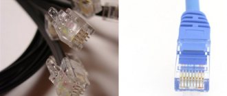
Why do you need a SATA Molex adapter (“SATA Molex”)?
Today, all modern ones come with a Molex connector. Despite this, the SATA Molex adapter itself (“SATA Molex”) is still relevant and in fairly high demand today. Why? For example, you want to install additional hardware on your personal computer in the form of hard drives (or in the form of an additional CD drive). However, the available vacancies are already occupied. What will you do in such a situation? The SATA Molex adapter will come to your rescue.
Designation of power circuits in foreign materials
Author: Kavka Published 05/23/2013. Created using KotoEd.
The little son came to his father and the little one asked: “What are Vcc, Vee, Vdd, Vss... and why are there so many of them?”
Every person interested in electronics encounters materials of foreign origin. And whether it is a circuit diagram of an electronic device or a specification for a chip, there may be many different designations for power circuits, which may well confuse a beginner or a radio amateur unfamiliar with this topic. There is enough information on the Internet to clarify this issue. The following is a summary of what has been found about the origin of the notation and its application.
VCC, VEE, VDD, VSS - where do these designations come from? Power circuit designations come from the field of transistor circuit analysis, which typically considers a circuit with a transistor and resistors connected to it. The voltages (relative to ground) at the collector, emitter, and base are designated VC, VE, and VB. Let's denote the resistors connected to the terminals of the transistor as RC, RE and RB. The voltage at the farthest (from the transistor) resistor terminals is often denoted VCC, VEE and VBB. In practice, for example, for an NPN transistor connected in a common-emitter circuit, VCC corresponds to the plus, and VEE to the minus of the power source. Accordingly, for PNP transistors it will be the other way around. Similar reasoning for N-type field-effect transistors and a circuit with a common source explains the designations VDD and VSS (D - drain, drain; S - source, source): VDD - plus, VSS - minus. The voltage designations at the terminals of vacuum tubes can be as follows: VP (plate, anode), VK (cathode, namely K, not C), VG (grid).
As written above, Vcc and Vee are used for bipolar transistor circuits (VCC - plus, VEE - minus), and Vdd and Vss for field-effect transistor circuits (VDD - plus, VSS - minus). This designation is not entirely correct, since microcircuits consist of complementary pairs of transistors. For example, in CMOS microcircuits, the plus is connected to the P-FET sources, and the minus to the N-FET sources. However, this is the traditional, established designation for power circuits, regardless of the type of conductivity of the transistors used. For dual-supply circuits, VCC and VDD can be interpreted as the most positive and VEE and VSS as the most negative voltages in the circuit relative to ground. For microcircuits powered by one or more sources of the same polarity, minus is often designated GND (ground). The ground can be different, for example, signal, connection to the body, grounding.
Here is a list of some notations (far from complete).
As you can see, designations are often formed by adding a word, one or more letters (possibly numbers) that correspond to letters in a word reflecting the function of the circuit (for example, like Vref). Sometimes the designations Vcc and Vdd may be present on one microcircuit (or device), then it could be, for example, a voltage converter. This could also be a sign of double nutrition. In this case, usually Vcc corresponds to the power supply to the power or peripheral part, Vdd to the power supply to the digital part (usually Vcc>=Vdd), and the minus power supply can be designated Vss. The combination of various technologies, traditions, or some other reasons in modern microcircuits has led to the fact that there is no clear criterion for choosing one designation or another. Therefore, it happens that the designations are “mixed”, for example, they use VCC together with VSS or VDD together with VEE, but the meaning is usually preserved - VCC > VSS, VDD > VEE. For example, almost everywhere, you can find in the specifications for microcircuits of the 74HC series (HC = High speed CMOS), 74LVC, etc., the power designation as Vcc. Those. The specification for CMOS (CMOS) chips uses the designation for bipolar transistor circuits. It was not possible to find any standard texts (ANSI, IEEE) on this topic. That is why the words “maybe”, “sometimes”, “usually” and similar ones appear in the text. Despite this, the information provided is quite enough to help you navigate foreign materials on electronics a little better.
Source
Characteristics
| Power | 1 W |
| Input type | Fixed voltage |
| Input voltage | 5V (DC) |
| Output type | Bipolar |
| Output voltage | ±12V (DC) |
| Output current | ±42 mA |
| Efficiency | 82 % |
| Output voltage stabilization | No |
| Galvanic isolation | From the entrance |
| Isolation voltage input-output | 1000V (DC) |
| Short circuit protection | Short term |
| Working temperature | -40 |
+85 °C
Shipment of converters from a warehouse in Moscow is carried out only by pre-order by e-mail.
What it is?
In fact, a SATA Molex adapter is the simplest device, which consists of two connectors for connecting to connectors, connected by four pieces of cable. Previously, devices with a Molex connector were powered using the following four contacts: +5V; Earth; Earth; +12. The SATA power connector has fifteen pins. It is divided into five groups and has a sequence of +3.3V; Earth; +5V; Earth; +12V.
There is also a less common SATA Molex adapter (“SATA Molex”) for connecting power to the CD drive from a laptop. This device has a more compact connector due to the fact that it has only six +5V contacts (instead of fifteen) and ground.
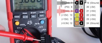
ATX connector pinout
| Pin | Name | Color | Description |
| 1 | 3.3V | Orange | +3.3 VDC |
| 2 | 3.3V | Orange | +3.3 VDC |
| 3 | COM | Black | Ground |
| 4 | 5V | Red | +5 VDC |
| 5 | COM | Black | Ground |
| 6 | 5V | Red | +5 VDC |
| 7 | COM | Black | Ground |
| 8 | PWR_OK | Gray | Power Ok is a status signal generated by the power supply to notify the computer that the DC operating voltages are within the ranges required for proper computer operation (+5 VDC when power is Ok) |
| 9 | 5VSB | Purple | 5 VDC Standby Voltage (max 10mA) 500mA or more typical |
| 10 | 12V | Yellow | +12 VDC (may sometimes have a colored stripe to indicate which rail it’s on) |
| 11 | 3.3V | Orange | +3.3 VDC |
| 12 | -12V | Blue | -12 VDC |
| 13 | COM | Black | Ground |
| 14 | /PS_ON | Green | Power Supply On (active low). Short this pin to GND to switch power supply ON, disconnect from GND to switch OFF. |
| 15 | COM | Black | Ground |
| 16 | COM | Black | Ground |
| 17 | COM | Black | Ground |
| 18 | -5V | White | -5 VDC (2002 v1.2 made optional, 2004 v2.01 removed from specification) |
| 19 | 5V | Red | +5 VDC |
| 20 | 5V | Red | +5 VDC |
/PS_ON activated by pressing and releasing the power button while the power supply is in standby mode. Activating /PS_ON turns on the power supply.
In several power supply units pin-12 may be Brown (not Blue), pin-18 may be Blue (not White), and pin-8 may be White (not Gray). In addition, some PSU violates color coding of wires.
Pin 9 (standby) supply 5V even when PSU is turned off. Pin 14 goes from 0 to 3.7 when PSU switch is turned on.
Shorting pin 14 (/PS_ON) to GND (COM) causes power supply to switch ON and PWR_OK to change to +5V.
This article promises to be quite explanatory and theoretical. Today we will take a closer look at an item that is so relevant in our time of technology - an adapter. This will be a SATA Molex adapter (“SATA Molex”). In this article you will find answers to your questions, for example, what it is, what it is intended for, what function it performs, and others.
Relay design, designation and parameters
An electromagnetic relay is actively used to control various actuators, switch circuits, and control devices in electronics.
The relay design is quite simple. Its basis is a coil consisting of a large number of turns of insulated wire.
soft iron rod is installed inside the coil The result is an electromagnet. There is also an anchor . It is attached to a spring contact . The spring contact itself is fixed to the yoke . Together with the rod and the armature, the yoke forms a magnetic circuit.
If the coil is connected to a current source, the resulting magnetic field magnetizes the core. He, in turn, attracts the anchor. The anchor is mounted on a spring contact. Next, the spring contact closes with another fixed contact. Depending on the relay design, the armature may mechanically control the contacts differently.
Relay device.
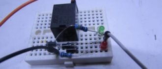
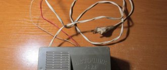
In most cases, the relay is mounted in a protective housing. It can be either metal or plastic. Let's look at the relay device more clearly, using the example of an imported electromagnetic relay Bestar . Let's take a look at what's inside this relay.
Here is the relay without the protective housing. As you can see, the relay has a coil, a rod, a spring contact on which the armature is attached, as well as actuating contacts.
On circuit diagrams, an electromagnetic relay is designated as follows.
The relay symbol in the diagram consists of two parts. One part ( K1 ) is the symbol of the electromagnetic coil. It is designated as a rectangle with two terminals. The second part ( K1.1 ; K1.2 ) are groups of contacts controlled by the relay. Depending on its complexity, a relay can have a fairly large number of switched contacts. They are divided into groups. As you can see, the designation shows two groups of contacts (K1.1 and K1.2).
How does a relay work?
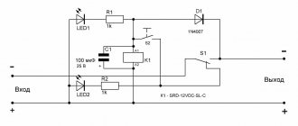
The principle of operation of the relay is clearly illustrated by the following diagram. There is a control circuit. This is the electromagnetic relay K1 itself, the switch SA1 and the power battery G1. There is also an actuator circuit that is controlled by a relay. The executive circuit consists of load HL1 (signal lamp), relay contacts K1.1 and battery G2. The load can be, for example, an electric lamp or an electric motor. In this case, the HL1 signal lamp is used as a load.
As soon as we close the control circuit with switch SA1, current from power battery G1 will flow to relay K1. The relay will operate and its contacts K1.1 will close the actuator circuit. The load will receive power from battery G2 and lamp HL1 will light up. If you open the circuit with switch SA1, then the supply voltage will be removed from relay K1 and the contacts of relay K1.1 will open again and the lamp HL1 will turn off.
Switched relay contacts can have their own design. For example, a distinction is made between normally open contacts, normally closed contacts and switching contacts. Let's look at this in more detail.
Normally open contacts
Normally open contacts are relay contacts that remain open until current flows through the relay coil. To put it simply, when the relay is turned off, the contacts are also open. In diagrams, relays with normally open contacts are designated like this.
Normally closed contacts
Normally closed contacts are relay contacts that remain closed until current flows through the relay coil. Thus, it turns out that when the relay is turned off, the contacts are closed. Such contacts are shown in the diagrams as follows.
Switching contacts
Switching contacts are a combination of normally closed and normally open contacts. Switching contacts have a common wire that switches from one contact to another.
Modern widespread relays, as a rule, have switching contacts, but there may also be relays that have only normally open contacts.
For imported relays, normally open relay contacts are designated by the abbreviation NO . And normally closed contacts NC . The common relay contact is abbreviated COM. (from the word common - “general”).
Now let's turn to the parameters of electromagnetic relays.
Parameters of electromagnetic relays.
As a rule, the dimensions of the relays themselves allow their main parameters to be printed on the housing. As an example, consider the imported relay Bestar BS-115C . The following inscriptions are written on its body.
Relay design, designation and parameters
An electromagnetic relay is actively used to control various actuators, switch circuits, and control devices in electronics.
The relay design is quite simple. Its basis is a coil consisting of a large number of turns of insulated wire.
soft iron rod is installed inside the coil The result is an electromagnet. There is also an anchor . It is attached to a spring contact . The spring contact itself is fixed to the yoke . Together with the rod and the armature, the yoke forms a magnetic circuit.
If the coil is connected to a current source, the resulting magnetic field magnetizes the core. He, in turn, attracts the anchor. The anchor is mounted on a spring contact. Next, the spring contact closes with another fixed contact. Depending on the relay design, the armature may mechanically control the contacts differently.