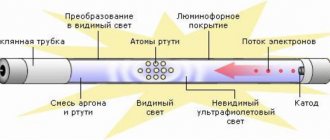
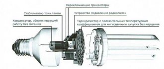
A fluorescent lamp (LL) is a glass tube filled with an inert gas (Ar, Ne, Kr) with the addition of a small amount of mercury. At the ends of the tube there are metal electrodes for applying voltage, the electric field of which leads to gas breakdown, the occurrence of a glow discharge and the appearance of electric current in the circuit. The glow of the gas discharge is pale blue and very weak in the visible light range.
But as a result of an electrical discharge, most of the energy passes into the invisible, ultraviolet range, the quanta of which, entering phosphorus-containing compounds (phosphor coatings), cause a glow in the visible region of the spectrum. By changing the chemical composition of the phosphor, different glow colors are obtained: for fluorescent lamps (FLLs) various shades of white have been developed, and for decorative lighting you can choose lamps of a different color. The invention and mass production of fluorescent lamps is a step forward compared to low-efficiency incandescent lamps.
Radio as a hobby
Repairing a fluorescent lamp
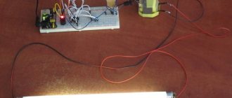
For several years I have been using a lamp with a tubular 18-watt fluorescent lamp. It (the lamp) did not cause any particular complaints... Apart from replacing burnt-out fluorescent lamps, there were no operational failures. But, as they say, nothing lasts forever...
Some time ago, when I tried to turn on the lamp, a bang was heard inside it, accompanied by a flash. The lamp was immediately de-energized, removed and pushed onto the far shelf in the pantry. Given its advanced age, the first decision was to throw the lamp in a landfill. Later, it was decided to try to repair it.
Let's start the renovation.
We disassemble the lamp and remove the fluorescent lamp. The first step is to check the lamp filament with an ohmmeter for breakage. The filaments turned out to be intact, and accordingly the lamp turned out to be in good working order and suitable for further use.
After opening the lamp, I was immediately struck by the terrible condition of the factory power cord, which was located inside the lamp body. The cord insulation cracked in many places, lost its elasticity and crumbled right under my fingers.
This is what the power cord looks like after ten years of use.
This state of the wire poses the following dangers:
-possibility of electric shock;
- the possibility of a short circuit and, as a result, fire;
Therefore, we change this cord first!
We continue to work... A popping sound inside the lamp clearly indicated a failure of the electronic ballast.
Removing the electronic ballast
A visual inspection did not reveal any burnt resistors. The mains fuse was also good. The mains fuse is the leftmost part on the ballast plate and is designated F1.
But the electrolytic capacitor with a nominal value of 4.7 µF x 400V turned out to be swollen
In order to carry out further repairs without blindness, I had to search the Internet for circuit diagrams of electronic ballasts. There are a great variety of them, and they are very similar to each other. The difference is only in the ratings of some parts, the presence/absence of additional protective elements and the type of transistors.
An attempt to compare the ballast diagram from my lamp with diagrams from the network showed that, in our case, additional elements were included in the ballast diagram. Therefore, in order not to rack my brains, I had to draw up a circuit diagram using a printed circuit board.
First of all, in such cases, we check the transistors. Both transistors turned out to be unusable with broken B-K junctions. This ballast uses transistors of the EB13003 type, which are analogues of the MJE13003 transistor, but have a different pinout from the original. This must be taken into account when replacing failed transistors.
Further inspection revealed that resistors R2, R3, R4, R5, R6, R7 had become unusable. The nature of the malfunction for all resistors is similar - an increase in resistance to 1 MΩ or more.
Failed elements are marked with red circles on the circuit diagram
All capacitors (except for the above electrolyte C2) turned out to be serviceable.
Instead of unusable ones, we solder in resistors of the MLT-0.125 type with the required values.
Instead of EB13003 transistors, we solder some Chinese type S13003.
We assemble the lamp in the reverse order.
Test activation... Everything worked. ))
The question of finding out the cause of failure of radio components is always interesting. In relation to this lamp, or more precisely, to its electronic ballast, my thoughts are as follows... After the repair, I noticed that the body of the lamp in the area where the electronic ballast is installed noticeably heats up. I didn’t pay any attention to this before. Heating indicates that the radioelements are operating under severe temperature conditions. In my opinion, this is one of the main reasons for the failure of radio elements. The first one that apparently failed due to overheating was the 4.7 µF x 400V electrolytic capacitor, which is a filter after the diode bridge. The deterioration of rectified voltage ripple suppression increased the level of voltages applied to the transistor junctions. Next, one of the transistors flew out, and then, according to the domino principle, another one flew out, along the way, the resistors in the base and emitter circuits burned out.. And that’s all.. Next was the repair.
Source: www.myhomehobby.net
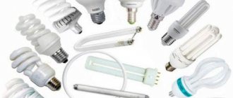
Fluorescent lamps (FL) are still used for lighting today, despite the fact that LED lamps provide them with strong competition. Linear tubular lamps are most often installed in offices, garages, and factories; compact fluorescent lamps (CFLs) are installed at home and in the same types of premises as listed above. They have characteristic malfunctions, so in this article we will look at how to repair fluorescent lamps.
Description of design
Fluorescent lamps differ in the shape of the tubular bulb, they are:
This is typical for CFLs, where the bulb is a tube twisted into a spiral or U-shaped. This is necessary to reduce the size while maintaining the length and area of the emitted surface.
In general, the bulb of a fluorescent lamp is a glass tube into which mercury vapor and inert gases are pumped. There are two spirals installed in the flask, one at each of its ends.
When the discharge burns in the lamp, ultraviolet light is emitted to convert it into visible light; the inner surface of the bulb is covered with layers of phosphor.
Tubes come in different diameters and lengths. Typically, the longer the lamp, the more powerful it is.
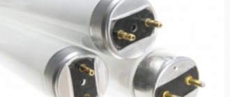
As already mentioned, such lamps have two spirals. They are needed to heat the gases and power the lamp after it is started. Two pin contacts from the spirals come out of the flask on each side.
This connection method is called a pin socket of type G. Depending on the distance between the pins, sockets of type G13 and G5 are distinguished. In which the pins are located at a distance of 13 and 5 mm, respectively.
Power circuit and normal operation
Fluorescent lamps differ from ordinary lamps in that for them to work it is not enough to simply connect its terminals to a 220V AC network. The power supply circuit assumes the operation of a fluorescent lamp with a so-called ballast - ballast control device. They come in two types:
Electromagnetic ballasts are considered obsolete, but are still often used to this day. They are not as efficient and produce light with barely noticeable flickering (low ripple), but they are reliable and easy to repair. Therefore, let's look at them first.
To light a lamp, you need to break through its gas gap; to do this, you need to create a pulse of increased voltage. Therefore, an energy storage device – a choke – is installed in series with the lamp.
But such a scheme will still not work; it is necessary to control the process of heating the coils and the accumulation of energy. The spirals are heated to provoke the emission of electrons, which should result in a discharge in the ionized gas. In tubular fluorescent lamps the discharge is glowing.
Schematic diagram
This is a large part of this electronic ballast; the Chinese did not include the inductor and capacitor here.
Actually, a diagram faithfully copied from a printed circuit board. The rating of the electronic components that made it possible to do this was determined not only “by appearance,” but also using measurements, with preliminary desoldering of the components from the board. In the diagram, the resistor values are indicated in accordance with the color coding. Only with regard to the choke, I allowed myself not to unwind the existing one to determine the number of turns, but measured the resistance of the wound wire (1.5 Ohms with a diameter of 0.4 mm) - it worked.
First assembly on the circuit board. I carefully selected the component values, regardless of size and quantity, and was rewarded - the light bulb lit up the first time. Ferrite ring (10 x 6 x 4.5 mm) from an energy-saving light bulb, its magnetic permeability is unknown, the diameter of the wire of the coils wound on it is 0.3 mm (without insulation). The first start-up is mandatory through a 25 W incandescent light bulb. If it is on and the fluorescent one initially blinks and goes out, increase (gradually) the value of C4, when everything worked and nothing suspicious was found, and removed the incandescent lamp, then reduced its value to the original value.
To some extent, focusing on the printed circuit board of the original source, I drew a signet for the existing suitable case and electronic components.
I etched the scarf and assembled the diagram. I was already looking forward to the moment when I would be satisfied with myself and glad to be. But the circuit assembled on a printed circuit board refused to work. I had to delve into and select resistors and capacitors. At the time of installation of the electronic ballast at the site of operation, C4 had a capacity of 3n5, C5 - 7n5, R4 resistance of 6 Ohms, R5 - 8 Ohms, R7 - 13 Ohms.
The lamp “fit” not only into the design; the lamp, raised all the way up, made it possible to comfortably use the shelf inside the secretary niche. Babay made the “room” feel comfortable.
A fluorescent lamp (LL) is a glass tube filled with an inert gas (Ar, Ne, Kr) with the addition of a small amount of mercury. At the ends of the tube there are metal electrodes for applying voltage, the electric field of which leads to gas breakdown, the occurrence of a glow discharge and the appearance of electric current in the circuit. The glow of the gas discharge is pale blue and very weak in the visible light range.
But as a result of an electrical discharge, most of the energy passes into the invisible, ultraviolet range, the quanta of which, entering phosphorus-containing compounds (phosphor coatings), cause a glow in the visible region of the spectrum. By changing the chemical composition of the phosphor, different glow colors are obtained: for fluorescent lamps (FLLs) various shades of white have been developed, and for decorative lighting you can choose lamps of a different color. The invention and mass production of fluorescent lamps is a step forward compared to low-efficiency incandescent lamps.
ATTENTION! LECTURE SITE.ORG is conducting a weekly survey. TAKE PART. JUST 1 MINUTE.
Repair of fluorescent lamps. Replacing the electronic ballast
Sometimes such a malfunction occurs, after installing and connecting a lamp with two fluorescent lamps, the lamp works properly. Several months pass and the lamp begins to turn on with one lamp. You start turning the lamp in the sockets, change the starter, but there is no result. What to do and what to do, how to repair a lamp with fluorescent lamps yourself?
Lamp with two fluorescent lamps
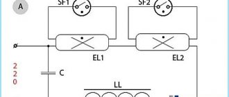
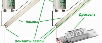
First, let's look at the diagrams of such lamps with fluorescent lamps:
The diagram in Fig. 8.1 contains:
· two fluorescent lamps;
A fluorescent lamp has two filament coils. The lamps, starter and throttle are connected in series in the electrical circuit. The capacitor is connected in parallel.
The diagram in Fig. 8.2 contains:
· two fluorescent lamps;
Connecting fluorescent lamps in Fig. 8.2 is no different from the connection diagram for lamps in Fig. 8.1. Two wires, phase and neutral, have a branch in this circuit.
And the simplest circuit of a lamp with one lamp is shown in Fig. 8.3, where the capacitor, lamp and starter in the circuit are connected in parallel. The inductor is connected in an electrical circuit - in series.
Similar lamps are also found with three lamps. The very essence of the matter is not this - not the number of lamps.
Malfunctions of fluorescent lamps
The reasons for not turning on a lamp with one lamp or a lamp consisting of two lamps or more, when one of the lamps of the lamp does not turn on, may be the following:
1. malfunction of the lamp itself;
2. no contact with the throttle;
3. no contact with starter;
4. break in the wires.
You can check the electrical circuit of the lamp and determine where exactly the break is located with a probe. After you have purchased the lamp, check all the contact connections of the lamp.
Possibility of starting with burnt-out equipment
Repairing fluorescent lamps also has its own little tricks. For example, there was an urgent need to start such a lighting device, but the starter was faulty, and there was no way to replace it. This circuit element itself serves to heat the filaments in the fluorescent tube.
Well, what if, for example, the throttle fails? Nowadays you can’t find it in all stores.
Throttleless activation
It is quite possible to prolong the operation of a burnt-out light fixture. There is a way in which you can turn on a fluorescent fluorescent lamp without a throttle and starter (connection diagram in the figure). Of course, this method is not suitable for everyone; you need to have at least a little understanding of electrical engineering.
Throttleless switching circuit
Voltage is supplied after a short circuit of the filaments. The rectified voltage doubles, which is quite enough to start the lamp (in theory, this function is performed by the inductor). Capacitors C1 and C2 (in the diagram) must be selected for 600 V, and C3 and C4 - with a rated voltage of 1,000 V. After some time, mercury vapor, of course, will settle in the area of one of the electrodes, and the light from the lamp will become much less bright. It will be possible to get rid of this simply by changing the polarity, i.e. simply by deploying the reanimated burnt-out LL.
Starterless inclusion
There are lighting devices that are designed exclusively for operation without a starter. Such lamps are marked RS. If such a tube is installed in a lamp equipped with a breaker, the lamp burns out very quickly. This happens due to the need for more time to warm up the spirals of such fluorescent tubes. The starter's durability is short, it often burns out, and therefore it makes sense to consider the possibility of how to turn on a fluorescent lamp without it. To do this, you will need to install secondary transformer windings. If you remember this information, then the question will no longer arise of how to light a fluorescent lamp if the starter burns out (connection diagram below).
Thus, without extra costs, you can even assemble a fluorescent lamp with your own hands.
Connection diagram without throttle and starter
Troubleshooting procedure
Before looking for a breakdown, make sure there is voltage; perhaps its absence is the reason why the fluorescent lamp does not light up. If this is not the reason, we look for it in this order.
Replace the starter if:
- turn on the light and nothing happens;
- the bulb glows only at the edges;
- the light flashes with a strobe;
- The starter lights up, but the lamp does not start.
Please note that manufacturers recommend replacing fluorescent lamps and starters at the same time.
Replace the light bulb if:
- it flashes with a strobe light;
- the edges of the flask are black;
- it glows, but the brightness is not enough (it shines weakly);
- The lamp does not work.
A typical breakdown of budget lamps is the destruction of lamp holders and loss of contact. The high temperature of a closed lamp causes the destruction of plastic fastening elements and connectors. If possible, replace them, bend the contacts if the condition is satisfactory.
A possible malfunction is a burnt-out choke, often this breakdown is visible visually, a discolored, melted terminal.
If you really find a malfunction, to repair the lamp you will have to replace the choke with a working one. You can check the functionality with a multimeter; the resistance is good, about 30-40 ohms. Before placing a lamp in a non-working lamp, make sure that the choke is not closed. Otherwise, you will lose your worker too.
Sometimes wires break down - the vibration of the lamp breaks off a wire near the lamp holder or choke. In this case, repairing a fluorescent lamp comes down to restoring contact. Owners of old-style lamps were spared these faults.
If you have a lamp with electronic ballasts made in China and replacing the light bulb did not solve the problem, most likely the problem is in the electronic unit. In most cases, you can fix it yourself with a soldering iron and a multimeter at your disposal. Below we will go into detail on how to repair the electronic ballast of a fluorescent lamp with your own hands.
Checking the infrared diode
Indeed, almost every home has such an LED. They have found wide application in remote controls. Let's imagine a situation where the remote control has stopped switching channels, you have already cleaned all the keyboard contacts and replaced the batteries, but it still does not work. So you need to look at the diode. How to test IR LED?
The human eye does not see the infrared radiation in which the remote control transmits information to the TV, but your phone's camera does. Such LEDs are used in night illumination of video surveillance cameras. Turn on the phone's camera and press any button on the remote control - if it is working, you should see flickering.
The methods for checking an IR LED and a regular one with a multimeter are the same. Another way to check if an infrared LED is working is to solder a red LED parallel to it. It will serve as a visual indicator of the operation of the IR diode. If it flickers, it means signals are being sent to the diode and the IR diode needs to be replaced. If the red does not flicker, then the signal is not being received and the problem is in the remote control itself, and not in the diode.
In the remote control circuit there is another important element that receives radiation - a photocell. How to check a photocell with a multimeter? Turn on resistance measurement mode. When light hits a photocell, its conductivity state changes, then its resistance also changes downward. Observe this effect and make sure it is working or broken.
Repair instructions
Now we will look at the main faults that can be fixed without much investment. Let's start with the electronic ballast, because in its circuit there are quite a lot of elements that can fail, and besides, tubular fluorescent lamps with electronic ballasts are more common today.
Ballast
The most common fault is transistor breakdown. This failure can only be determined by removing the transistors from the circuit and checking them with a tester. In the whole transistor, the transition resistance
400-700 Ohm. As the transistor burns, it pulls a resistor in the base circuit with a nominal value of 30 ohms.
There is also a fuse or a low-resistance 2-5 Ohm resistor on the board; most likely it will have to be replaced, at which point the repair will end. You may additionally have to change the diode bridge or its elements.
A breakdown of 47n film capacitors (half a microfarad) or a resonance capacitor in the filament circuit is rare. There have been cases when all of the above is intact and in good order, but the lamp does not work, the reason lies in the DB3 dinistor. If you have checked all the elements of the circuit, then try replacing the dinistor.
You may decide that it will be cheaper to purchase a new electronic ballast than to repair a broken one. Replacing the starting equipment should not be difficult, because the connection diagram is printed on the device itself. Upon careful study, it is easy to understand, L and N are terminals for connecting to a 220V network.
Download books
• V.V. Fedorov. Fluorescent lamps / The principles of operation of fluorescent lamps are discussed in detail. Production process, switching circuits, parameters. Lots of theory, good textbook, djvu, 2.72 MB, downloaded: 12599 times./
• P.A. Dormakovich. Gas-light advertising. / Issues of operation, installation and development of tubular discharge lamps with a cold cathode., djvu, 2.86 MB, downloaded: 4248 times./
• A manual for repairing energy-saving lamps / A manual for repairing energy-saving lamps. It tells how you can give a second life to an energy-saving lamp. Or put one together from two or three., doc, 25.62 MB, downloaded: 28061 times./
• Repair of energy-saving lamps / Interesting and useful selection of links, articles and tips on lamp repair. Thanks for the work to the author luna1509!!!, pdf, 1.32 MB, downloaded: 6520 times./
I remind you that many books on electronics and electrical engineering can also be downloaded from the page.
What is electronic ballast and what is it for?
The use of electronic starting and control equipment or apparatus (abbreviated electronic ballasts) provides a significant increase in the useful life of lighting equipment of this type.
Electronic ballasts are the next round of development of lamp ignition systems. The electronic ballast is produced as a separate module with contacts for supplying power supply and contacts for connecting one or more lamps. This unit replaced a simple but outdated circuit with a throttle and starter. All modern lamps are usually equipped with this design.
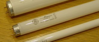
T8 fluorescent lamps
T8 lamps have a glass bulb diameter of 26 mm. The widely used T10 and T12 lamps have diameters of 31.7 and 38 mm respectively. LDS with a power of 18 W are usually used for lamps. T8 lamps do not lose their functionality during supply voltage surges, but if the voltage drops by more than 10%, lamp ignition is not guaranteed. Ambient temperature also affects the reliability of the T8 LDS. At sub-zero temperatures, the luminous flux decreases and failures in lamp ignition may occur. T8 lamps have a lifespan of 9,000 to 12,000 hours.
Electronic ballast device
An electronic ballast is a complex electronic device. Includes:
- Interference filter: necessary to level out the influence of interference from and into the electrical network;
- Rectifier: needed to convert AC to DC;
- Optional: power corrector;
- Anti-aliasing filter: used to reduce ripple;
- Inverter: increases the voltage to the required level;
- Ballast: analogue of an electromagnetic choke.
In some models, the inverter can be supplemented with a brightness control. To do this, you need an external dimmer (either manual or automatic based on a photoresistor). A lot of schemes have been developed. The element base of electronic ballasts for daytime fluorescent lamps is very diverse: from powerful field-effect transistors in a bridge circuit with loads of hundreds of watts, to driver microcircuits in low-power lamps. But nevertheless, the operating algorithm is the same.
In a simplified form for one fluorescent lamp, the diagram looks like this:
Those. the circuit consists of only two components: a fluorescent lamp and an electronic starter. From an electrician's point of view, this is much simpler than the classic lamp circuit using an electromagnetic choke and starter. Terminals N and L are supplied with mains voltage. Ground pin – grounding. For electronic ballasts to operate, connecting a grounding contact is not mandatory and serves only for safe operation.
The connection diagram for two lamps is similar.
There are no additional elements in it; the circuit is supplemented only by a second lamp, the terminals of which are connected directly to the electronic unit.
Electronic ballast circuits are complex and consist of many electronic components. It is very difficult for a person without an engineering education to understand the diagram. In addition, not every electrician will be able to understand the internal structure.
One of the options for the electronic ballast circuit diagram
This is a fairly simple circuit for an electronics engineer. In a simplified sense, the scheme works as follows. Rectification is carried out by a full-wave rectifier - a diode bridge. Ripple smoothing is performed by an electrolytic capacitor designed for a voltage higher than the mains voltage, since the amplitude value of the sinusoid for the alternating current mains is approximately one and a half times higher than the mains voltage (√2*220V). The remaining processes are controlled by the microcircuit. Field-effect transistors are responsible for supplying voltage to the lamps. Then the converter operates autonomously, the frequency does not change.
Knowledge of electronics allows you to create a power supply circuit for a fluorescent lamp from low-voltage sources. The scheme turns out to be quite compact. The most important thing is to wind the transformer correctly.
Schematic diagram of powering a fluorescent lamp from a low-voltage source
Advantages of different types of ballasts
Before choosing and, especially, buying ballast of one type or another, it makes sense to understand their differences from each other. The advantages of EmPRA include:
- moderate cost;
- high reliability;
- Possibility of connecting two lamps of half power.
Electronic ballasts appeared much later than their throttle counterparts, which means they have a longer list of advantages:
- small dimensions and weight;
- with the same light output, energy consumption is 20% lower than that of electronic ballasts;
- almost do not heat up;
- operate absolutely silently (EMPRA often hums);
- no lamp flickering at mains frequency;
- lamp life is 50% higher than with a choke;
- The lamp starts instantly, without “blinking”.
But, of course, you have to pay for all these advantages - the cost of an electronic device is significantly higher than the price of a throttle device, and reliability, alas, is still lower. In addition, if the power of the electronic ballast is lower than the power of the lamp, then, unlike the electromagnetic one, it will simply burn out.
Operating principle of the starter
Whatever circuit is used to start a fluorescent lamp. The general operating principle remains unchanged. In principle, similar processes occur when using a throttle and starter. There are only three phases:
- Initial heating of the electrodes. In electronic ballasts this occurs by a fairly gentle increase in voltage on the tungsten filaments.
- Arson. At this moment, the circuit delivers a high-voltage pulse (usually about one and a half kilovolts). This is enough for electrical breakdown of gas and mercury vapor. The ignition voltage of fluorescent lamps is significantly higher than the combustion voltage.
- Combustion. After a high-voltage pulse, the circuit reduces the voltage to that required to maintain the glow discharge. The AC frequency at the electrodes can reach 38 kHz depending on the circuit.
In electronic ballasts, the igniting impulse is provided by an electronic circuit. In the classical scheme - due to the energy accumulated by the inductor. Warming up of the electrodes is also provided by electronic ballasts. With a starter switching circuit, the electrodes warm up at the moment the starter contacts close. It can be replaced with a push button.