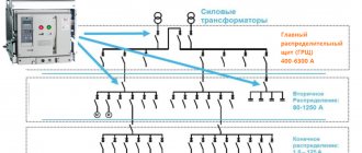
SIP is a self-supporting insulated wire. It is called self-supporting because it contains, as a rule, in the zero core or separately, a steel wire core, which allows the wire not to stretch under its own weight. This wire is intended for use in overhead power lines, that is, for pulling “at height.” In addition, it is they who usually carry out the pulling of the overhead line from the highway to the house.
The design of this wire does not involve the use of terminal blocks, much less twists. Moreover, a direct connection of two SIP wires is not made at all, since they can transmit current with a voltage of up to 35 kW. For electrical interfacing of self-supporting insulated wires, special piercing clamps are used.
Design and principle of operation
The clamps presented in stores are designed to do their job as quickly as possible; in addition, the technology of their use ensures the safety of further operation. These positive properties of SIP piercing clamps are associated with the use of high-quality materials in their design, which is associated with strict compliance with Russian and international electrical standards and constant production control.
There are several fundamental factors that you need to understand regarding the operation of a piercing clamp for SIP wire:
- It is necessary to ensure contact between the two wires. The puncture must be made between the main conductor and the counter conductor. This ensures proper operation of the entire system.
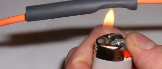
- The cores must be passed through special holes on the body of the clamping product. To do this, you need to pull back the upper bolt for connection. This operation is performed until the bolt head breaks off.
The outer part of a modern clamp for puncturing SIP wires is covered with a layer of high-quality fiberglass. The working part of the piercing device is made of durable polymer materials. This ensures that the clamping mechanism itself will be resistant to destruction under the influence of sunlight, and the housing will not allow moisture to enter, regardless of pressure and the general severity of weather conditions.
Uninterrupted quality when using clamps for SIP wires is due to their production according to modern technologies and integral quality control of the finished product at all stages of production. Based on the use of high-quality materials, the service life of a SIP puncture is about 30-40 years.
When installing branch clamps for SIP wires, you need to make punctures right through the insulation located on the conductors. Assumptions that this will serve as a negative criterion for the entire strength of the electrical installation are erroneous. Before work, you need to make sure that the place where the puncture is attached is sealed.
You should remember and take seriously the fact that the installation of the piercing clamp must be done correctly and the first time. It will no longer be possible to remove it after installation. Operating the device twice is also prohibited.
You can learn how to install the product by watching the video:
Manufacturers
Leading companies producing valves are Ensto, Niled and others.
Ensto
The Finnish company Ensto produces fittings for all types of SIP. Lightweight models are available, made of plastic, as well as those made of durable alloys for harsh working conditions. A feature of the piercing clamps produced by the company is the pyramidal design of the teeth, which increases the contact area and reduces the penetration of teeth into the wire, which reduces its damage. This contact part is similar in characteristics to clamps in the form of dies.
Niled
The French company Niled is the main supplier of fittings for SIPs in Russia. A characteristic feature of the products is adaptation to local conditions. Insulation piercing devices for domestic small-section wires have been developed for the Russian market. The range of supplies meets the technical requirements of RAO UES divisions.
How to install correctly
As mentioned above, when this electrical installation is installed, there is no need to uninstall the cable itself. For example, you need to connect a branch to an existing line. How can such a connection of two wires be made (in fact, this will also be the fastening of the beginning of the outlet section)?
- The branch clamp is placed on the live line.
- The end of the wire for the branch section is inserted into the second groove.
- The bolt head is manually tightened until it stops.
- Then, using a spanner wrench, the bolt is tightened to such an extent that its head simply falls off. This indicates that the teeth of the device have reached the metal strands of the SIP wire.
The entire process is carried out only with dielectric gloves. Installation is quite simple, but it is not worth carrying out if you are not an electrician. There are certain restrictions and requirements regarding admission to this type of work. This is especially true for areas under voltage.
Advantages of branch compressors
In work, the use of such technology provides a number of undeniable advantages, in particular:
- Ability to work under voltage. Using the clamp, you can make a tap from the main SIP without de-energizing the line.
- The ability to connect wires made of different metals (copper and aluminum), provided that they are single-core.
- Tightening control - using a breaker head (in particular, in the P95 branch clamp it is aluminum) or using a dynamometer. In the first case, breaking the head means achieving the required pressure.
- Convenient removal method using a second screw.
- The case is hermetically sealed for the corresponding models. Leak tests are carried out in water using high voltage current.
- Compensation for temperature expansions.
- Speed of installation work.
- There is a wide range of wire gauges that can be connected this way.
Winch and frog
A winch and frog-tender mounting clamp are required to give the line final tension
One of the main qualities that a frog should have, and which few people pay attention to, is its weight.
It shouldn't be heavy. This is due to the fact that the installer, when working on a support, often has to cling it to the SIP with one outstretched hand. And at the maximum distance from the rack. The lighter the frog, the easier it will be to do this.
The second requirement is strength. The tension in the wires can reach 500 kg. Therefore, before work, always inspect it externally and check the reliability of the moving elements.
There must be a surface inside the frog that does not damage the insulation of the wire and at the same time allows tension to be transferred to it
Please note that such clamps for wire SIP-4 and SIP-1,2,3 have significant differences and are not interchangeable
Technical characteristics and brands of tension clamps Ensto, Niled, Sicam, KVT:
Ensto
Sicam
Niled
KVT
As for the winch, the main requirements for it:
reverse
It is necessary that with its help you can not only tighten the wire, but also loosen or release it.
sufficient cable length
To tension the line, it is desirable, but not necessary, to have a winch cable up to 3 m long. Otherwise, you will have to re-hook the frog several times in order to extend the required sag.
the presence of an additional block to increase the traction force
More details about the different brands of winches, characteristics, issues that arise during their operation (whether they can lift loads or not) are stated in the article: “Winch for installation of self-supporting insulated insulated wires”
Technical characteristics and brands of winches and dynamometers for SIP from Ensto, Sicam, Niled, KVT:
KVT
Sicam
Niled
Ensto
Installation of piercing clamps
The algorithm for organizing a tap using a piercing clamp is quite simple, but there are several nuances that need to be paid attention to:
- As a rule, devices of this type are designed in such a way that installation work can be carried out without turning off the power supply. That is, the tightening mechanism is isolated from the contact area. But, nevertheless, the electrician performing the connection must have the appropriate clearance group.
- To separate the core, special devices (separating wedges) should be used.
Separating wedges
You cannot use other available tools for this purpose, for example, a screwdriver, since there is a high probability of damaging the insulation. Two wedges should be installed with an interval of 20.0-25.0 cm, which allows you to separate the core from the bundle at a distance of 4-6 cm, this is quite enough for work. If possible, you can loosen the support clamp.
- The fittings are suitable for aluminum and copper conductors. It is also an ideal adapter, preventing the formation of a galvanic couple.
- It is prohibited to connect two or more self-supporting insulation insulation systems to one fitting, unless the design requires this. This prohibition is due to the fact that proper reliability and tightness of the contact will not be ensured.
- Clamps must not be reused. There are several reasons for this:
- It is impossible to determine the required clamping force, since the mechanism is “broken,” which threatens to compress the SIP above the breaking force threshold.
- the contact teeth are deformed during crimping. Consequently, when reused, they may no longer pierce the insulating coating or provide the required contact area.
- The teeth of the new clamp have a special coating in the form of silicone grease, which ensures sealing of the cut insulation. A previously used device will no longer have such lubrication; therefore, moisture will get under the insulation.
- It is imperative to put on the cut of the connected SIP the sealed cap that comes with the clamp. There are models with built-in cut sealing. Such devices are preferable, since individual parts tend to get lost; in addition, when working at height, it is inconvenient to reach into a bag every time for a sealed tip.
- To tighten the connecting fittings, use spanners (13 or 17, depending on the design of the clamp) with an insulating coating.
Dielectric spanners Having dealt with the nuances, let's move on to the procedure:
- Lightly “release” the tightening bolt. This must be done in order not to damage the insulating coating.
- The core and SIP are inserted into the eyes intended for them. In this case, it is necessary to ensure that the cables are clearly in the middle of the clamping contacts. After this, the bolt must be tightened by hand, thereby securing the electrical wires.
- Holding the clamp from the bottom, the bolt is tightened using a spanner wrench (usually 13).
- You need to tighten it until the bolt “breaks”. This indicates that the required clamping force has been achieved.
Input of electricity into the building
As mentioned above, laying the input cable is the prerogative of the employees of the energy sales organization.
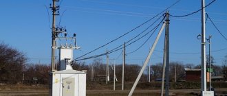
Connecting a house to a power line can be done in three ways:
- Overhead line from pole to building. Aluminum wires without insulation are used. The method is unsafe; in recent years, they have been trying not to use it.
- Input from the overhead line using SIP. Due to the reliability of the line and operational safety, this method of delivering electricity is considered a priority.
- Armored underground cable. The method is considered the safest (especially for wooden buildings), but its disadvantage is its high cost. Rarely used.
Despite the advantages of SIP described above, there are many opponents of this technology when it comes to residential buildings (even if they are houses made of brick or stone). Many experts consider the SIP insulation layer to be not reliable enough for residential buildings.
To prevent undesirable consequences in the event of an insulation rupture, cables must be positioned at a certain distance from building structures.
The fact is that overhead lines are protected from short circuits by an automatic device that operates under conditions of high currents, and shutdown, if necessary, occurs with some delay. Even in a short period of time, the resulting electric arc can ignite building structures, especially if they are wooden.
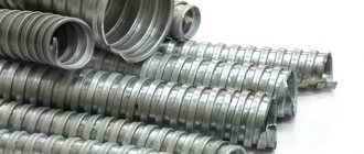
However, most specialists prefer SIP. The numerous advantages of this type of cable cancel out the disadvantages, especially since safety can be ensured using a special thick-walled metal pipe into which the cable is laid.
The pipe allows you to neutralize the effects of an electric arc
It is recommended to pay close attention to the inlet and outlet holes of the pipe: they should be covered with corrugated material to prevent the wire from chafing on the metal
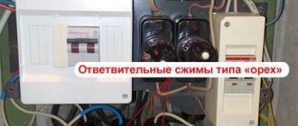
One of the ways to organize the input is to switch from aluminum SIP cores to an internal cable, which is used for wiring throughout the building. The main requirement for such a cable is fire resistance. In addition, the area up to the switchboard must be additionally protected with a circuit breaker. An automatic device is all the more necessary if wires without insulation are used, connected to a piece of cable.
Note! The rating of the machine must be one value higher than the value of the input panel
Basic mistakes in SIP installation
Mistake #1. Rolling out SIP on the ground
The installation of self-supporting insulated wires cannot be treated in the same way as the installation of bare overhead line wires.
Particular attention should be paid to the safety of SIP insulation. Therefore, you cannot roll out SIP wires on the ground.
For rolling there are special rollers that are suspended on anchor supports.
Mistake #2. Reuse of piercing clamps
Piercing clamps are used for SIP branches from the main to the consumer. The use of piercing clamps allows for tapping without removing the insulation, but their reuse is prohibited. The reason is simple. The head of the piercing clamp breaks off, and repeated, reliable tightening will not work. You can remove them, but you cannot use them a second time.
Mistake #4. Two anchor clamps per bracket
You cannot attach more than one anchor clamp to one anchor bracket. This applies to both supports and building facades. The rule is simple: One anchor clamp, per anchor bracket.
Mistake #4. Incorrect selection of connecting sleeves
When selecting connecting sleeves, the length of the sleeve for connecting the neutral conductor must be longer than the sleeves on the phase conductors. This is done to strengthen the connection.
Mistake #6. Connecting sleeve sleeves are not crimped
After connection, be sure to crimp the steel rings on both sides of the connecting sleeve. The rings will be crimped around the SIP insulation and will secure the connection made.
Mistake #7. Incorrect connection of SIP and bare wires
At the junction of the bare wire and the SIP, the first wire must be cleaned of oxide and lubricated with a special paste to prevent re-oxidation.
Mistake #9. Incorrect connection of street lighting
You cannot insert two street lighting wires with a cross-section of 1.5 mm into one P6 clamp. Such a connection breaks the tightness of the contact.
Error No. 10-11-12. Using non-profile devices for rolling out SIPs
- Do not use sheeting rollers without a polymer coating.
- When rolling out SIPs, you cannot work without a swivel.
- You cannot check the sag of the booms and the tension force without a dynamometer.
Elesant.ru
Other articles in the section: Overhead power lines
- Types of power transmission line supports by material
- Types of supports by purpose
- Overhead power lines with SIP wires
- Wooden supports for overhead power lines
- Reinforced concrete power transmission line supports
- Reinforced concrete power transmission line supports
- Power line support structures
- Tension of overhead power line wires
- SIP installation mistakes that should not be made
- Preparatory work for installation of overhead power lines
Manufacturers
In addition to our Russian manufacturers, foreign electrical companies produce and import electrical products to us.
Some of them: Enstio, Feman, Install, Niled, ETP.
Here, for example, is a branch clamp from ENSTO, article number SLIP 12.1.
The characteristics are as follows:
- Weight: 0.11kg
- Main line, mm²: 10–95 mm²
- Branch conductor, mm²: 1.5–50 mm²
- Conductor diameter: 3–16 mm
- Al/Cu 10-95 mm² with Al/Cu 1.5–50 mm²
SLIP12.1 The clamp is easy to install. Can be used to connect a live consumer. The hexagonal break head is isolated from the tightening bolt and the contact group of the clamp.
Can be used for 2x16 and 4x16 SIPs.
Installation of the piercing clamp
To connect the branch to the overhead line, in addition to the connecting clamp with piercing plates, you must have a SIP cable and a wrench.
Important! Despite the presence of insulation on the wires and the design features of the connecting devices, which exclude the possibility of electric shock, when installing them, it is imperative to use personal protective equipment. These include rubber gloves, dielectric mats and the same wrench
The installation procedure is as follows:
- Step 1. Separate the wires on the main line from each other. For this purpose, special dielectric wedges are used. In their absence, wooden ones can be used;
- Step 2. After the wedges are installed, you should unwind the bundle a few turns in the opposite direction and put the clamp on the core. The main line passes through the device, and the SIP cable can only be passed through on one side, since on the other side there is a cap on the terminal;
- Step 3: The drop cable must be straight. After this, it must be inserted into the hole in the connecting device until it stops. As a result, both conductors (main and branch) must be located in parallel;
- Step 4. The final installation step is to tighten the mounting bolts until the head is torn off. In this position, the terminals, which are located inside the connecting device and equipped with special teeth, pierce the insulation of the main line and the SIP cable and ensure stable transmission of electricity.
Installation process
The main mistakes made when installing connecting devices for SIP cables are:
- There have been several attempts to tighten the fastening bolts in the clamps. This should not be done, since the head of the bolt is broken, and it will not be possible to re-fasten it. Therefore, in case of incorrect fastening, it is better to replace the bolt;
- The SIP cable cores are connected as a result of improper installation. This may lead to a violation of safety requirements and also increase the risk of an emergency. This problem can be avoided by using dielectric wedges during the installation process;
- Placing more than one core in a clamp, which leads to unreliable contact. To prevent this situation, it is necessary to strictly follow the installation technology.
Requirements
For a reliable and durable connection of SIP cables, it is necessary that the connecting clamps meet certain requirements. Their body should be made of glass fiber reinforced plastic for better insulation of parts.
The plastic used for the manufacture of fittings must be durable and resistant to mechanical stress. In addition, the branch clamp must be immune to sunlight, ultraviolet rays and heat radiation.
After connecting the wires, the housing of the fittings must be perfectly sealed in order to prevent moisture from penetrating into the jumper. Oxidation of contacts can lead to a blackout or, even worse, a short circuit.
Connecting electrical cables
Let's start by connecting the electrical wires. Let's assume that we have three wires going into the electrical box, and they need to be connected to each other. How it's done? First, you need to cut off the excess cable and leave the cable at such a length that it does not interfere with the placement of the cables in the electrical box, but at the same time it is not too short, because a cable that is too short cannot be properly stripped and cannot be connected properly. It should extend about 5 cm out of the box, then we will trim it anyway.
Now we do the following: we strip each cable to a length of approximately 2–2.5 cm. We carefully cut it, trying not to damage the inner conductor. Here the technology is the same for all types of conductors - aluminum, copper, single-core and stranded.
We remove the insulation without damaging the cable, then be sure to clean the conductor, because in most cables it is coated with a thin layer of varnish to prevent corrosion of the conductive layer. We clean it with the end of the knife specially designed for this purpose, so as not to cut our hands or dull the knife.
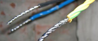
We twist the veins. You can twist them in any direction you like.
To do this, you can use pliers or your own hands, if you don’t mind them. Naturally, only multi-core cables are twisted. If you have a single-core cable, then we simply strip it. We perform the same procedure with the second cable, then with the third: remove the insulation, strip it, twist it. Then we take two cables, lean them against the insulation and tightly twist them like this:
Next, we apply the third cable, also insulation to insulation, and as tightly as possible - this is very important for the further operation of your electrical wiring - we wind it onto the other two cables
Most electricians recommend that after twisting, you cut the twist where the last cable ended. It ends a little earlier than the other two.
Why is this being done? First, we bite off the excess. We don’t need a strongly protruding twist, it’s inconvenient to insulate, and it won’t fit well in the box. Secondly, we get something like cold welding.
This is also very important, as it improves electrical contact and, therefore, the functionality of our wiring. With this connection our wiring will work much longer
Then we isolate the twist.
Why is it recommended to use two colors of electrical tape? In an electrical network, as we know, there is a phase and a “zero”.
In order not to constantly check with an indicator probe whether it is phase or “zero,” it is best to mark the phase wire, for example, with red or brown electrical tape. As a rule, phase wires in electrical networks are designated with these colors, and the neutral cable is either black or blue. If you don’t have blue or black electrical tape, you can use yellow or some other kind. We take electrical tape, start about 1 cm along the insulation and wrap it as tightly as possible.
Then we wrap a second layer of electrical tape to create reliable insulation. The insulating tape will not only insulate the cable, but also hold it together, because with aluminum strands it often happens that the strand weakens over time. Aluminum oxidizes slightly and twisting becomes unreliable. If we insulate everything tightly, then the electrical tape will additionally secure this twist. The twist will last much longer; there will be no need to disassemble it after 5-6 years and twist it. Twisted and cut. This can be done with pliers or a construction knife.
One more point: it is recommended to insulate electrical boxes in such a way that there is access to the electrical contact:
What is it for? The cable remains insulated, that is, a short circuit will not occur, but when repairing this wiring, it will be very easy for you to check whether it is a phase or “zero”, whether there is a phase or not. This check is easy to carry out, but the insulation remains reliable and does not in any way affect the performance of the connection. This is very convenient during repairs, since you don’t have to unwind the insulation and, therefore, everything can be checked under voltage - you don’t need to turn off the electrical packages and then turn them on again. They just opened the box, checked it, and that’s it. Thus, we connected three wires. In the same way, you can connect a larger number of wires, usually up to six. It will no longer work, because too much twisting becomes non-functional and inconvenient to use.
Types, their structure and principle of operation
Varieties and types of clamps for connecting wires work on a similar principle and have almost the same design. Products 2x16, 4x16 and others provide serial and parallel connections. In the first case, the connection is made using a clamp, which is mounted in different connectors. Protective dielectric caps are installed on the exposed cable ends. In the case of a parallel connection, it is necessary to use special clamps, thanks to which a diversion from the main line is organized.
The electrical connection can be made by piercing the outer insulating layer of the self-supporting cable. For this purpose, pyramid-shaped cloves are used. When making a puncture, they qualitatively fix the joint, preventing moisture from entering it.
The product itself has the following device:
- Frame. It will be sealed or waterproof. The first option is more relevant.
- Internal terminal element. It is made of one or several symmetrical plates equipped with spikes in the form of a cone or pyramid. They are installed in each slot.
- Fastening mechanism. This component is based on the use of a shear calibrated bolt head.
- Auxiliary systems for opening the contact elements of the product. They are used for emergency shutdown of the device.
- Tightening screw for fixing the conductor.
- Eyelet for installing SIP.
- The contact area on which the main core is mounted.
- The protective cap installed on the SIP contributes to high-quality insulation of the conductor.
- Eyelet for laying the main core.
A lubricant is located directly in the body, sealing the puncture site. Thanks to the lubricant, the possibility of the cable coming into contact with air or water is eliminated.
If the device for piercing the SIP wires does not have a bolt for dismantling, then the cable is disconnected by biting it off.
The Elektro House channel talked about the design features of products for fixing SIPs.
ZOI
Branch clamps with an insulation layer are designed for connecting neutral or phase mains with a voltage of up to 1 kW to a high-voltage line. The wire section is suspended directly on the clamp itself. Puncture devices are installed on the power lines and tightened using a special shear screw head. This ensures optimal force for fixing the teeth to the conductor, which will ensure high-quality contact and avoid damage. If necessary, the device can be dismantled using a wrench by unscrewing the lower head, which will remain intact.
ZZZRB IEK
Clamps of this type are used to branch one or two cables from the main line. This type of connection is used in facilities characterized by low humidity, where water cannot enter the device. The product labeling indicates the purpose of the clamp, as well as the number of conductors for the branch.
Devices with a shear head are designated as C, and the presence of the fraction “/” indicates the range of wire cross-sections on the main and secondary lines. The fundamental difference between this type of product is that piercing elements are available only on the main cable. On the branch it is necessary to dismantle the insulating layer.
OZPI
Self-supporting insulated wire SIP 2
The technology of modern branch clamps with insulation piercing (IPPI) is developing in the following areas:
- improved contact system;
- new materials for the manufacture of clamp bodies;
- controlled tightening force of the main bolt;
- increased tightness of connections;
- increasing ease of installation.
Modernization of contact group
- Plates made of aluminum alloys and with pyramidal-shaped teeth, placed in a checkerboard pattern (Fig. a below).
- Aluminum or copper plates with wedge-shaped teeth like a saw (Fig. b).
- Aluminum plates that combine the advantages of previous types (Fig. c).
OPPI devices from popular manufacturers: a – Ensto; b – (1 – Sicame and Simale, 2 – Niled); c – Sicame and Simale
Any of the three methods guarantees the creation of a puncture of insulation and reliable electrical contact with the current-carrying core of the SIP. The material of the phase wires is softer than the neutral wire and the teeth penetrate deeper into them. In any case, the shear head of the tightening bolt ensures the creation of reliable electrical contact while maintaining the required strength of the conductor.
The housings shown in Fig. The above models are made of glass fiber reinforced polyamide. They have good mechanical and electrical properties and withstand weathering well.
The tightening process of the main bolt is controlled due to the shear head. It provides only one-time use of the OPPI. However, you can use a torque wrench to create the required force. This option was used in early models of devices, but it turned out to be not very convenient.
Using specific torque charts for different models, you can use a torque wrench for secondary installation. In this case, you cannot be completely sure of the reliability of the connections, since the piercing teeth in the clamp used are deformed.
Installers prefer models with minimal tightening force.
Connecting the house to power supply
Connecting a SIP from the main line to the house is a subscriber connection and is carried out as part of a new connection or replacing old wires with a SIP. Before connection, a number of bureaucratic approvals are carried out, and the connection itself is made using 2×16 SIP wires, either independently or by calling professionals.
Obtaining approvals for a new SIP connection from the highway to the house
- In your area, you need to find a government agency responsible for energy sales in the area. In them you receive documents that you, as the owner or authorized person, have the right to connect;
- Order and receive a house connection project;
- If there is a support for a main line or a linear branch within a radius of 25 meters from the house, then you will connect from it. If the supports are removed, you will have to “fork out” for the installation of additional support.
Purchasing the necessary materials
For work you will need:
Note. The usual connection is single-phase (phase + zero) and a SIP with a cross-section of 2 × 16 mm2 is used for it.
- Two anchor clamps. The correct name is self-tightening wedge anchor clamps. Company brand NILEDPS 1500.
- Four piercing clips. Brand NILED PS 95– 2 pcs., P 4-2 pcs.
- A screw-in hook or wall bracket for attaching an anchor clamp to the front of a house.
Stages of work on connecting SIP
- Roll out the cable from the support to the house. SIPs cannot be rolled out on the ground, as the insulation may be damaged. Cable rollers are used for rolling;
- Attach the anchor clamp to the facade of the house together with the SIP;
- Pull the SIP from the house to the support. The height of entry into the house must be at least 2750 mm. The SIP should not be stretched like a string, but it should not sag too much.
- Secure the SIP to the support using a second anchor clamp. The anchor clamp is attached to the concrete support on a bracket, which is attached to the support with mounting tapes and staples.
- In the last stages, the SIP is connected to the VLI backbone and to the power supply cable of the house.
Connecting SIP to the main line
The SIP outlet is connected to the main wires of the VLI using piercing clamps. The design of the clamps is such that there is no need to strip the wire insulation. The wires are inserted into two clamp sockets and tightened with a common bolt.
In the figure you see the connection of the outlet to the house from the intermediate support.
Video: Installation of branch clamps
Note: A panel with a metering meter can be installed on the support. To do this, it will have to be lowered for visual inspection by inspection authorities, and a window must be provided in the shield. The meter can also be installed on the facade of the house, there are no restrictions.
Connecting SIP at home
There are two options for connecting your home:
- Bring SIP into the house. Only SIP 4 is suitable.
- Make a connection between the SIP and the power supply cable at home. It is better to use VVGng cable.
- Bracket;
- Anchor clamp;
- SIP;
- Piercing clamps;
- VVGng cable in corrugation.
- The connection between SIP and VVGng is made using piercing clamps (4).
- Any cable is introduced into the house through a sleeve. In a wooden house, the sleeve is surrounded by non-flammable material.
- The input cable is inserted into the electrical panel and an input, two-pole (this is our example) or four-pole circuit breaker is installed at the input.
Tags: machine, beat, sconce, upper, view, internal, harm, house, , clamp, isolate, insulation, cable, how, design, crown, , installation, voltage, crimp, connection, rule, principle, check, wire , project, pierce, laying, start-up, , work, repair, row, garden, twisting, connection, means, term, ten, type, current, installation, phase, facade, shield, electrical panel