Short circuit tripping current setting (Im)
Instantaneous releases or those triggered with a short time delay are designed to quickly turn off the circuit breaker in the event of large short-circuit currents. Their response threshold Im:
- for household circuit breakers it is regulated by standards, for example IEC 60898;
- for industrial circuit breakers, it is specified by the manufacturer in accordance with current standards, in particular IEC 60947-2.
A wide range of trip units are available for industrial circuit breakers, allowing the user to tailor the circuit breaker's protective functions to the specific load requirements (see Figure H31
,
H32
and
H33
).
| Release type | Overload protection | Short circuit protection | |||
| Household circuit breakers (IEC 60898) | Thermomagnetic (combined) | Ir = In | Lower setting Type B 3 In ≤ Im ≤ 5 In | Standard setting Type C 5 In ≤ Im ≤ 10 In | Upper settingType D10 In ≤ Im ≤ 20 In |
| Modular industrial vehicles switches | Thermomagnetic (combined) | Ir = In (not adjustable) | Lower setpoint Type B or Z3.2 In ≤ constant ≤ 4.8 In | Standard setting Type C 7 In ≤ constant ≤ 10 In | Upper setpoint Type D or K 10 In ≤ constant ≤ 14 In |
| Industrial circuit breakers (IEC 60947-2) | Thermomagnetic (combined) | Ir = In (not adjustable) | Constant: Im = 7 – 10 In | ||
| Adjustable: 0.7 In ≤ Ir ≤ In | |||||
| Adjustable: - Low setting: 2 - 5 In - Standard setting: 5 - 10 In | |||||
| Electronic | Long time delay 0.4 In ≤ Ir ≤ In | Short time delay, adjustable: 1.5 Ir ≤ Im ≤ 10 Ir Instantaneous operation (I), time not adjustable: I = 12 - 15 In |
50 In in the IEC 60898 standard, which according to most European manufacturers is an unrealistically large value (MG = 10-14 In).
For industrial use, the values are not regulated by IEC standards. The values shown above are those that are commonly used.
Rice.
H31: Trip current ranges for overload and short circuit protection devices for low voltage circuit breakers
Fig.
H32: Trip curve of thermomagnetic combination circuit breaker
Ir: overload tripping current setting (thermal or long-time relay) Im: short-circuit tripping current setting (magnetic or short-time relay) Ii: release setting instantaneous short-circuit breaking current Icu: breaking capacity
Rice.
H33: Circuit breaker electronic trip curve
What are the current characteristics of circuit breakers and how they differ from each other?
As is known, the main organs for triggering a circuit breaker are thermal and electromagnetic releases.
The thermal release is a bimetal plate that bends when heated by a flowing current. Thus, the release mechanism is activated, and in the event of a prolonged overload, it is triggered with an inverse time delay. The heating of the bimetallic strip and the tripping time of the release directly depend on the overload level.
The electromagnetic release is a solenoid with a core, the magnetic field of the solenoid at a certain current draws in the core, which activates the release mechanism - instantaneous operation occurs during a short circuit, due to which the affected section of the network will not wait for the thermal release (bimetallic plate) in the circuit breaker to warm up.
The dependence of the response time of the circuit breaker on the strength of the current flowing through the circuit breaker is precisely determined by the current characteristic of the circuit breaker.
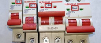
Probably everyone has noticed the image of the Latin letters B, C, D on the bodies of modular machines. So, they characterize the multiple of the setting of the electromagnetic release to the nominal value of the machine, indicating its time and current characteristics.
These letters indicate the instantaneous operation current of the electromagnetic release of the machine. Simply put, the response characteristic of a circuit breaker shows the sensitivity of the circuit breaker - the lowest current at which the circuit breaker will turn off instantly.
Slot machines have several characteristics, the most common of which are:
- – B — from 3 to 5 ×In;
- – C — from 5 to 10 ×In;
- – D — from 10 to 20 ×In.
What do the numbers above mean?
Let me give you a small example. Let's say there are two machines of the same power (equal in rated current), but the response characteristics (Latin letters on the machine) are different: machines B16 and C16.
The operating range of the electromagnetic release for B16 is 16*(3.5)=48. 80A. For C16, the instantaneous response current range is 16*(5.10)=80. 160A.
At a current of 100 A, the B16 circuit breaker will turn off almost instantly, while the C16 will not turn off immediately, but after a few seconds from thermal protection (after its bimetallic plate heats up).
In residential buildings and apartments, where the loads are purely active (without large starting currents), and any powerful motors are turned on infrequently, the most sensitive and preferable for use are machines with characteristic B. Today, characteristic C is very common, which can also be used for residential and administrative buildings.
As for characteristic D, it is just suitable for powering any electric motors, large engines and other devices where there may be large starting currents when they are turned on. Also, due to the reduced sensitivity during short circuit, machines with characteristic D can be recommended for use as input ones to increase the chances of selectivity with lower group ABs during short circuit.
Agree, it is logical that the response time depends on the temperature of the machine. The machine will turn off faster if its thermal element (bimetallic plate) is heated. And vice versa, when you turn it on for the first time when the bimetal of the machine is cold, the shutdown time will be longer.
Therefore, on the graph, the upper curve characterizes the cold state of the machine, the lower curve characterizes the hot state of the machine.
The dotted line indicates the maximum operating current for machines up to 32 A.
Automatic switch: principle of operation and device in pictures
The main purpose of the machine is to eliminate emergency situations in connected current circuits. They come in two types:
- Short circuits (SC) or “short circuits”, as they are called in the jargon of electricians.
- Overload.
Short circuits arise due to the connection of electrical circuits with minimal resistance to the current voltage circuits, which create enormous currents, depending on the power of the supply sources.
Short circuit currents can burn through not only the insulation of the air during its ionization, but also melt the metal of the wiring, cause a fire, and cause other disasters.
Numerous welding machines operate on the principle of controlling short circuit currents, and people successfully use them. But suddenly appearing short circuits cause enormous harm.
Overloads are dangerous because they imperceptibly create overheating of the insulation and damage it. Due to the defects that arise in it, dangerous leakage currents appear, which only an RCD can detect and eliminate.
Overloads are also a common cause of equipment fires.
The circuit breaker design consists of two separate modules, each of which operates by responding primarily to short circuits or overloads. This:
- Electromagnetic cut-off.
- Thermal release.
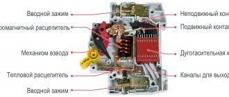
A simple kinematic diagram shows the design of a circuit breaker and its operating principle.
Electrical current flows from the mains to the load through the closed main contacts and the trip solenoid coil. The thermal effect is perceived by the bimetallic plate, and the force effect is perceived by the electromagnet core.
In a critical situation, the bimetal or core hits the rotary lever, knocking it out of engagement with the latch that holds the main contact in the on state. Under the influence of a strong tripping spring, it quickly opens the electrical circuit.
Structurally, all manufacturers implement this principle in their designs. Therefore they are slightly different on all models. But the following picture gives a general idea of the internal structure.
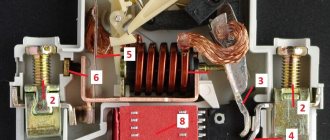
The operating principle of the cut-off release electromagnet in two words
When current flows through the winding, a magnetic field is created in its core, which serves as a magnetic circuit.
If the current reaches a critical value, then the magnetic energy shoots out the core, overcoming the tension of the holding spring. Then the striker knocks out the latch.
A modern electromagnetic release has small dimensions and is connected to the contacts with flexible conductors.
Thermal circuit breaker release: how easy it is to work
The design consists of two connected plates: steel and brass. They have different linear expansion: temperature dependence. When heated, the bimetal bends in one direction, and when cooled, it bends in the opposite direction.
The current passes through a winding fixed to a bimetallic plate. During an overload or short circuit, the bimetal acts on the rotating mechanism, which turns off the machine, de-energizing the connected consumers.
Characteristic Z
Also has a spread when operating on direct and alternating voltage and is designed to provide maximum protection for electronic control devices. The work curve is shown below:
When operating on alternating voltage, shutdown occurs when 2–3 ratings are reached, when operating at constant voltage, 2–5.
As you can see, choosing a circuit breaker to protect electrical circuits is not such a simple task as it seems at first glance. Therefore, when choosing a circuit breaker, it is necessary to compare not only the nominal data (voltage, current, phase), but also to know the operating characteristics of the system for which the circuit breaker is selected, so that the circuit breaker you choose fully provides protection for your equipment.
What is shown in the graph of the time current characteristic
Using the example of a 16-amp circuit breaker with a time-current characteristic C, let's try to consider the response characteristics of circuit breakers.
On the graph you can see how the current flowing through the circuit breaker affects the dependence of its shutdown time. The multiple of the current flowing in the circuit to the rated current of the machine (I/In) is shown on the X-axis, and the response time, in seconds, is shown on the Y-axis.
It was said above that the machine includes an electromagnetic and thermal release. Therefore, the graph can be divided into two sections. The steep part of the graph shows protection against overload (operation of the thermal release), and the flatter part shows protection against short circuit (operation of the electromagnetic release).
As you can see in the graph, if you connect a load of 23 A to the C16 machine, it should turn off in 40 seconds. That is, if an overload of 45% occurs, the machine will turn off after 40 seconds.
The machine is able to respond instantly to large currents that can lead to damage to the insulation of electrical wiring due to the presence of an electromagnetic release.
When a current of 5×In (80 A) passes through the C16 circuit breaker, it should operate in 0.02 seconds (this is if the machine is hot). In a cold state, under such a load, it will turn off within 11 seconds. and 25 sec. (for machines up to 32 A and above 32 A, respectively).
If a current equal to 10×In flows through the machine, then it turns off in 0.03 seconds in a cold state or in less than 0.01 seconds in a hot state.
For example, if there is a short circuit in a circuit that is protected by a C16 circuit breaker and a current of 320 Amperes occurs, the circuit breaker shutdown time range will be from 0.008 to 0.015 seconds. This will remove power from the emergency circuit and protect the machine itself, which has short-circuited the electrical appliance and electrical wiring, from fire and complete destruction.
Machines with what characteristics are preferable to use at home?
In apartments, if possible, it is necessary to use category B machines, which are more sensitive. This machine will work from overload in the same way as a category C machine. But what about the case of a short circuit?
If the house is new, has a good condition of the electrical network, the substation is located nearby, and all connections are of high quality, then the current during a short circuit can reach such values that it should be enough to trigger even the input circuit breaker.
The current may be small in the event of a short circuit, if the house is old, and there are bad wires with huge line resistance going to it (especially in rural networks, where the phase-to-zero loop resistance is high) - in this case, a category C machine may not work at all. Therefore, the only way out of this situation is to install machines with type B characteristics.
Consequently, the time-current characteristic of type B is definitely more preferable, especially in dacha or rural areas or in old buildings.
In everyday life, it is quite advisable to install type C on the input machine, and type B on group line circuit breakers for sockets and lighting. In this way, selectivity will be maintained, and somewhere in the line, during a short circuit, the input machine will not turn off and “extinguish” the entire apartment.
Similar materials on the site:
Automatic switch: how to choose according to science and live safely
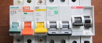
A huge number of manufacturers and a wide range of their machines, designed for different operating conditions, complicate the choice of their purchase.
When purchasing, you should use only a scientific approach, without relying on the opinion of even familiar electricians. For this purpose, all leading factories apply markings directly on the body of the machine module. I will give an example for Legrand.
You need to select an automatic circuit breaker module based on at least 9 characteristics:
- the value of the effective voltage and the shape of the current;
- number of poles;
- the value of the rated current of the protected circuit;
- time-current characteristic;
- load power;
- ultimate switching capacity;
- current limiting class;
- selectivity of action;
- degree of housing protection IP.
You will have to take their action into account comprehensively.
We look at the voltage of the circuit breaker: initial step
You must immediately pay attention to the conditions for reliable operation of the module. The fact is that such protections can be created for universal operation in DC and/or AC circuits.
An example is the well-known series of Soviet and Russian protections, produced as the AP-50 circuit breaker.
They have different levels of tension. It may not always be suitable for reliable operation in a particular wiring. We need to check it carefully.
Individual modules can only be created for use in AC circuits.
Number of poles of the circuit breaker: step No. 2
Household machines are made to operate in a single-phase or three-phase circuit. When protecting the input during an accident, they remove the phase and zero potentials, completely de-energizing the supply circuit.
For outgoing lines, only the phase potential is turned off, and the zero remains in operation. This is quite enough to eliminate the accident and create a simpler connection diagram.
Step 3: Selecting a Current Circuit Breaker - Hidden Secrets
Important: the ambient temperature greatly affects the response time of the protection. All checks and calculations are carried out at +30 degrees . Real conditions require taking temperature coefficients into account.
Normal operation of the machine requires taking into account 4 current values:
- Nominal value.
- Conditional non-disconnection.
- Conditional release.
- Long term acceptable.
The rated current value is written In (In). It is indicated on the housing and is used as a base value for selection, operation and protection checks. Such a load must pass through closed contacts for a long time without disconnecting them.
The conditional non-disconnection current is the value I=1.13×In. With such a load, the protection should not turn off in less than 1 hour with a rating of up to 63 A and 2 hours with a more powerful one.
The characteristic of the conditional tripping current determines the value that reliably breaks the excess load.
The long-term permissible current value was introduced to take into account the temperature state of the wiring without excessive heating, taking into account the characteristics of the current-carrying ability: type of metal and cross-section.
I presented all these values in a visual graph for copper. You can use it when calculating a new wiring project. I took the data from reference books, but did not carry out electrical checks.
If someone takes on this work, I will definitely publish the results. But it is necessary to check, because with long-term permissible currents in the copper wire of squares 4 and 6, an interesting pattern is visible.
I didn’t bother with aluminum: it’s dangerous in everyday life. For those users who are interested in this issue, I suggest comparing its characteristics with copper using the following table.
The selection of a circuit breaker when designing wiring must be carried out according to the characteristics of its rated current. This analysis is carried out sequentially in 3 steps:
- Calculation of line current based on the load of connected consumers.
- Selecting the modular protection rating based on the closest value of the standard range of current values.
- Selection of conductor cross-sections for current loads.
Each of the three components is important. Mistakes made are difficult to correct. Therefore, each step should be re-checked.
Single or group consumers, as well as a single-phase or three-phase power supply circuit, impose their own characteristics on the calculation of the connected line current using their own formulas. This is the most difficult part of the analysis.
Step 4: time-current characteristics of the circuit breaker - the basis for the correct choice of design type
Electrical network loads are random or natural. They always change when consumers connect.
Incandescent lamps and heating elements with resistive resistances do not produce such effects as turning on inductive devices: electric motors, chokes, transformers. Cable lines have capacitance.
Any switching on of the device is associated with the creation of aperiodic components that form transient processes. They are characterized by various surge currents.
The design of the circuit breaker must take these phenomena into account and ensure normal power supply to consumers in any complex, changing situation.
It is technically difficult to create a simple and reliable circuit breaker with a universal set of capabilities to meet these requirements. Electrical engineering science has taken a different path: dividing loads according to the types of reactive components and creating protection modules for each.
For this purpose, the time-current characteristic of the circuit breaker is used, which has 3 types: B, C and D. They have different parameters for setting the protection against transient currents.
On the graph, the abscissa axis shows the ratio of the current load current to the nominal value, and the ordinate axis shows the shutdown time in seconds and their fractions.
Type B is used for consumers with characteristic resistive loads: heaters, lighting circuits, long power lines.
Type C is used for mixed circuits with socket groups and consumers that create moderate loads when the electric motors are turned on.
Type D is chosen for non-domestic consumers: power transformers and loads with high currents during equipment startups.
If you use a type B circuit breaker for your home, it may trigger falsely when you turn on a washing machine or dishwasher, electric pumps, or powerful vacuum cleaners.
A type D circuit breaker simply will not react to danger when it does not reach its setting value, but will require protection of the equipment from inrush current.
According to their characteristics, type C circuit breakers are best suited for work in home wiring. But their settings still need to be checked qualitatively.
Selecting a circuit breaker based on power - step No. 5: is it necessary to do it?
It is the issue of choosing machines based on load power that authors of articles for the Internet pay a lot of attention to. Therefore, I decided to express my opinion too. And your task is to take it into account or speak out against it.
The trick is that the electrical characteristics of any household appliances are indicated in watts, and protections are marked in amperes. There are no other secrets here anymore.
Bloggers simply transfer the load, expressed in power, through household voltage into current. They do this through new tables, diagrams, and calculators.
I propose to abandon this idea, and calculate the protection module based on the rated current, taking into account the current-voltage characteristic. There will be fewer errors, and it will become easier to find them. I understand that the choice is yours.
Step 6: Ultimate Switching Capacity - Critical Characteristic of the Protection Module
We proceed from the fact that in nature there are no contacts that can withstand any load. They always have a limit above which they simply burn out.
The manufacturer determines this value experimentally and shows it with a number inside a rectangle.
Typically, modules are created for short-circuit currents up to 4.5, 6 or 10 kiloamperes. When the machine has differences in the maximum switching capacity (MCC) for alternating and direct current circuits, they are indicated separately. Moreover, each value is assigned its own symbol: “~”, “-”, “~/-”.
This value, in principle, depends on the technical condition of the electrical wiring - its resistance. It is included in the project and depends on many factors:
- length of highways;
- cross-section and quality of conductors;
- number and condition of connecting contacts;
- distance from the supply transformer substation;
- maintenance conditions.
From practice:
- For older buildings with dilapidated aluminum wiring, the PKS is 4,500 amperes.
- Copper electrical wiring provides short-circuit currents of 6 kiloamperes.
- When the consumer is close to the transformer substation, the circuit breakers should be installed at 10 kA.
If you do not select the machine according to its maximum switching capacity, its contacts may become welded due to the emergency current. Then the shutdown will not occur, and the entire connected load will burn out.
Step 7: circuit breaker current limiting classes - what are the characteristics
The speed of short circuit tripping directly affects equipment safety, and protection modules do not operate in the same way. Performance indicators allow you to select machines that operate in gentle or extreme equipment modes.
To make the action clearer, let’s consider their operation using the example of the duration of one voltage period of a current or voltage sinusoid (denoted T).
It includes two harmonic half-waves. For a standard frequency of 50 hertz, the cycle time is 20 milliseconds (ms).
The maximum value of the current or its amplitude is achieved at a quarter of a period or half of a half-cycle. On the graph I showed the average time indicators of three current limiting classes: 1, 2 and 3.
Class No. 1 is the longest, and therefore extreme. Its time is just over 10 ms. For clarity, shown as T/2. It is simply not marked on the body of the machine gun.
Class #2 is intermediate in speed. Such protection should work within 6÷10 ms. On the graph it is averaged as 1/2(T/2).
Class No. 3 is the fastest and most economical with a response time of 2.5÷6 ms, which I designated as 1/3(T/2).
Current limiting classes 2 and 3 are marked on the housing under the PKS rectangle with a square with the corresponding number.
Step 8: selectivity of the machine is the key to high-quality shutdown of the accident
The point of choosing this parameter is the selective ability of the protection to correctly localize a short circuit or overload and leave the equipment in working order.
Let me explain with a simple example of apartment wiring.
Any outlet can become a source of short circuit for various reasons. The accident can be turned off by circuit breaker No. 3 of the apartment panel, No. 2 of the entrance panel, or No. 3 of the house panel.
However, it makes sense to de-energize a floor or entrance/house only if switch No. 3 fails, using this function as a backup. First of all, apartment protections must work reliably.
Therefore, they are configured for faster response or lower current settings during commissioning. This possibility should be considered when choosing a design.
Sometimes difficulties arise with setting selectivity on the input machine. For such cases, you can purchase a special selective circuit breaker.
Its design has a mechanism that provides two paths for current flow: the main one and an additional one for the thermal release with its associated power contacts.
The selectivity resistor inside the additional channel delays the operation of its contact by the selectivity setting. And the main channel works like a normal one.
A general shutdown of the protection occurs after the contacts of both channels are broken, which the cutoff electromagnet can also perform.
A similar mechanism can be useful to owners of private houses or cottages, although in most cases selectivity can be ensured by choosing the performance characteristics and adjusting the current settings of conventional modules.
Checking the selectivity of protection operation must be carried out before putting them into operation and periodically during operation.
Final step No. 9: degree of protection of the housing for rooms with high humidity
Typically, machines are installed in an apartment or other panel, protected from the penetration of water and foreign objects. But sometimes they have to be connected to mobile equipment or extension cords.
When such devices are used in wet areas, attention should be paid to the technical ability of the housing to operate in a hazardous environment.
It is marked with an IP index with numbers indicating the degree of protection. On conventional machines, the designation IP20 is sufficient. It is shown in the accompanying documentation.
In all the previous material, I deliberately do not advertise any machine manufacturer. I advise you to choose a protection module according to its technical characteristics, actually testing them on test benches. A brand is a good thing, but testing is more important.
Human protection is paramount!
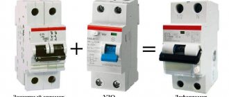
In conclusion, let's talk about another device that should become the main protective device in your shield. In the article we looked at aspects of network and device protection, now we’ll talk about how to protect people. For this purpose, a so-called automatic differential current switch is used, the purpose of which, in addition to monitoring currents, is to monitor “leaks” and abnormal changes in the network. Simply put, this type of machine recognizes that unauthorized changes in characteristics are occurring in the network, falling into the category of “insulation damage”, “possible human contact with live wires”, etc.
Such detection leads to instantaneous de-energization of a section of the network. Sometimes residual current circuit breakers are called RCD (Residual Current Device), MDZ (Differentiated Protection Module). They can be used in combination with other machines. The main difference between this machine is that it works to protect people from electric shock. Such devices are most relevant for connecting bathrooms and baths (preferably with maximum sensitivity) and kitchens. But today many people prefer to install such switches on all sections of the network in the apartment.
We hope that this article will be useful to you when choosing an RCD and, as a result, your electrical network and electrical appliances will be reliably protected.
Errors made by electricians not only those who are new to protection work
Selecting an automatic switch correctly according to its technical characteristics does not mean that it will reliably turn off an accidental malfunction.
I came to this conclusion at work, doing numerous tests of these protections on specialized stands. Therefore, I once again recommend that the purchased machine be subjected to rigorous tests under real load and time characteristics measured before commissioning.
Electrician error No. 1: phase-zero loop check not performed
The essence of this test is that the short circuit current, which the machine should sense and turn off, simply depends on Ohm’s law on the resistance of the circuit connected to it.
In other words, the length of the wires from the circuit breaker to the socket and further to the consumer connected to it can reduce the short circuit current to such a limit when the setting for the protection to operate is higher: the switch will not trip.
This possibility is checked with special devices.
It must be followed.
Rated short-circuit breaking capacity (Icu or Icn)
| The breaking capacity of a low-voltage circuit breaker is related to the power factor (cos φ) of the faulted section of the circuit. A number of standards provide typical values for this ratio. |
The breaking capacity of a circuit breaker is the maximum (expected) current that a given circuit breaker is capable of turning off and remaining operational. The current value mentioned in the standards is the effective value of the periodic component of the fault current, i.e. When calculating this standard value, it is assumed that the aperiodic component of the transient current (which is always present in the worst possible short-circuit case) is zero. This rated value (Icu) for industrial circuit breakers and (Icn) for household circuit breakers is usually specified in kA.
Icu (rated ultimate breaking capacity) and Ics (rated service breaking capacity) are defined in IEC 60947-2 together with the relationship between Ics and Icu for the different utilization categories A (instantaneous breaking) and B (delayed breaking) discussed in subsection Others characteristics of the circuit breaker.
Tests to confirm the rated breaking capabilities of circuit breakers are regulated by standards and include:
- switching cycles consisting of a sequence of operations, i.e. switching on and off during a short circuit;
- phase shift between current and voltage. When the current in the circuit is in phase with the supply voltage (cos φ = 1), cutting the current is easier to achieve than at any other power factor. It is much more difficult to switch off the current at low lagging values of cos φ, with current switching off in a zero power factor circuit being the most difficult case.
In practice, all fault currents in electrical power systems typically occur at lagging power factors, and the standards are based on values that are generally considered typical for most power systems. In general, the higher the short circuit current (at a given voltage), the lower the power factor of the short circuit, such as near generators or large transformers.
In the table shown in Fig. H34
and taken from the IEC 60947-2 standard, the relationship between the standard values of cos φ for industrial circuit breakers and their ultimate breaking capacity Icu is indicated.
After carrying out the “tripping - time delay - closing / opening” cycle to check the ultimate breaking capacity (Icu) of the circuit breaker, additional tests are performed to ensure that as a result of this test the following are not deteriorated:
— electrical insulation strength; — separating ability; — correct operation of overload protection.
| Icu | cosφ |
| 6 kA | 0,5 |
| 10 kA | 0,3 |
| 20 kA | 0,25 |
| 50 kA | 0,2 |
Rice.
H34: Relationship between Icu and short-circuit power factor (cos φ) (IEC 60947-2)
Time-current characteristics of machines
The operation of automatic circuit breakers occurs due to the action of its main elements - thermal and electromagnetic releases. The design of the thermal release consists of a bimetallic plate that heats up under the influence of flowing current. As a result, it bends and activates the release mechanism. For operation, a long-term load is required, inversely proportional to the time delay. The level of overload directly affects the heating of the plate and the response time of the thermal release.
The main components of an electromagnetic release are a coil and a core. When the current reaches a certain level, the magnetic field of the coil draws in the core, under the influence of which the release mechanism is activated. The device responds instantly in case of short circuits, without waiting for the thermal release to heat up. The operation time of the machine depends on the strength of the current passing through the circuit breaker. This dependence is precisely the time-current characteristic of the protective device.
The Latin symbols B, C and D are marked on the body of each device. Each of them corresponds to the multiple of the setting of the electromagnetic release to the rated value of the machine. That is, with the help of these letters the instantaneous tripping current of the release or the sensitivity of the circuit breaker is displayed. This parameter indicates the minimum current at which the protective device is switched off instantly. Thus, the time-current characteristic of each specific machine is denoted in Latin letters. The symbol “B” corresponds to the characteristics 3-5 x ln, “C” – 5-10 x ln and “D” – 10-20 x ln.
The meaning of these figures must be considered using the example of two machines of equal power, that is, with the same rated current, for example, models B16 and C16. For switch B16, the operating range of the electromagnetic release will be 16 x (3-5) = 48-80 A. Accordingly, for the C16 circuit breaker this range will be within 16 x (5-10) = 80-160 amperes. Thus, in the presence of a current of 100 A, the B16 model will instantly turn off, and the C16 device will turn off only a few seconds after heating the bimetallic plate.
For residential and administrative buildings, the most suitable options are considered to be automatic machines marked B and C. This is due to the absence of large starting currents and the extremely rare switching on of high-power electric motors. Category D machines are used mainly in those facilities where there are powerful electric motors and other devices with high starting currents.
The time-current characteristic curve necessarily takes into account the temperature of the protective device itself. In the case of the first trip, it takes longer to turn off because the bimetallic strip is cold. When triggered again, when the plate has already been previously heated, the shutdown occurs faster.
What are circuit breakers
Unlike fuses, these elements can be reused. The first automatic disconnector appeared back in 1905. Improved elements are still used today.
What are they for?
Automatic switches (AB) disconnect the electrical circuit when a current flows in excess of the set value. These are the required wiring elements:
- to control current flows in electrical networks;
- to disconnect the circuit in an emergency.
Sometimes, to repair wiring, you need to de-energize a power line. This option is accomplished by pressing the AB toggle switch.
Switches are also used to switch off too high current or voltage in electrical circuits.
Wiring options are limited. To prevent overheating of the cable insulation and fire, it is necessary not to exceed the maximum ratings of the cord and all circuit elements. Compliance with this condition is monitored by AB.
One example of exceeding the permissible load is the simultaneous connection of a large number of powerful devices with weak electrical wiring. Constant operation of circuit breakers indicates the need to replace the cable or incorrect selection of the circuit breaker.
Faulty devices can lead to a short circuit. In this case, the lack of automation or the wrong choice of switches can cause a fire.
In addition, when connecting devices, a so-called error occurs. “starting current” is an instantaneous impulse, which can be large when several devices are connected simultaneously. In this case, the correct choice of the class of automatic shutdown devices is also important.
Operating principle of switches
The operating principle of an automatic electromagnetic release is based on the influence of the electromagnetic field created around a toroidal conductor during the passage of electric current. Its strength will be greater, the higher the charge.
To understand how AB works, you should consider the following figure. Near the center of the coil there is a rod that is attached to a spring. Too much current passing through the turns of the torus creates a strong electromagnetic field that can overcome the resistance of the spiral. As a result, the core is pulled inward, dragging with it a spring attached to a movable contact that breaks the circuit.
If the electromagnetic release does not work, the thermal disconnector, which is a bimetallic plate, comes into action.
Its function is to turn off the circuit when overloaded. The passing current heats the thermal element. Since the 2 types of metal of which it is composed have different coefficients of expansion, part of the plate bends and presses the line break lever.
How they work - automation design
The design of household switches includes 2 releases: thermal and electromagnetic. Since the first one reacts slowly (depending on the degree of current increase), the device includes a second disconnector to instantly respond to high current values when closing.
In addition, when the releases operate, an electric arc is formed due to physical phenomena. In order to avoid this, the AB design includes an element consisting of several plates. The electric arc is crushed and extinguished in this chamber.
What is shown in the graph of the time current characteristic
Using the example of a 16-amp circuit breaker with a time-current characteristic C, let's try to consider the response characteristics of circuit breakers.
On the graph you can see how the current flowing through the circuit breaker affects the dependence of its shutdown time. The multiple of the current flowing in the circuit to the rated current of the machine (I/In) is shown on the X-axis, and the response time, in seconds, is shown on the Y-axis.
It was said above that the machine includes an electromagnetic and thermal release. Therefore, the graph can be divided into two sections. The steep part of the graph shows protection against overload (operation of the thermal release), and the flatter part shows protection against short circuit (operation of the electromagnetic release).
As you can see in the graph, if you connect a load of 23 A to the C16 machine, it should turn off in 40 seconds. That is, if an overload of 45% occurs, the machine will turn off after 40 seconds.
The machine is able to respond instantly to large currents that can lead to damage to the insulation of electrical wiring due to the presence of an electromagnetic release.
When a current of 5×In (80 A) passes through the C16 circuit breaker, it should operate in 0.02 seconds (this is if the machine is hot). In a cold state, under such a load, it will turn off within 11 seconds. and 25 sec. (for machines up to 32 A and above 32 A, respectively).
If a current equal to 10×In flows through the machine, then it turns off in 0.03 seconds in a cold state or in less than 0.01 seconds in a hot state.
For example, if there is a short circuit in a circuit that is protected by a C16 circuit breaker and a current of 320 Amperes occurs, the circuit breaker shutdown time range will be from 0.008 to 0.015 seconds. This will remove power from the emergency circuit and protect the machine itself, which has short-circuited the electrical appliance and electrical wiring, from fire and complete destruction.
Machines with what characteristics are preferable to use at home?
In apartments, if possible, it is necessary to use category B machines, which are more sensitive. This machine will work from overload in the same way as a category C machine. But what about the case of a short circuit?
If the house is new, has a good condition of the electrical network, the substation is located nearby, and all connections are of high quality, then the current during a short circuit can reach such values that it should be enough to trigger even the input circuit breaker.
The current may be small in the event of a short circuit, if the house is old, and there are bad wires with huge line resistance going to it (especially in rural networks, where the phase-to-zero loop resistance is high) - in this case, a category C machine may not work at all. Therefore, the only way out of this situation is to install machines with type B characteristics.
Consequently, the time-current characteristic of type B is definitely more preferable, especially in dacha or rural areas or in old buildings.
In everyday life, it is quite advisable to install type C on the input machine, and type B on group line circuit breakers for sockets and lighting. In this way, selectivity will be maintained, and somewhere in the line, during a short circuit, the input machine will not turn off and “extinguish” the entire apartment.
Trip characteristics of protective circuit breakers
Class AB, determined by this parameter, is indicated by a Latin letter and is marked on the body of the machine before the number corresponding to the rated current.
In accordance with the classification established by the PUE, circuit breakers are divided into several categories.
MA type machines
A distinctive feature of such devices is the absence of a thermal release. Devices of this class are installed in circuits connecting electric motors and other powerful units.
Class A devices
Type A machines, as was said, have the highest sensitivity. The thermal release in devices with time-current characteristic A most often trips when the current exceeds the nominal value AB by 30%.
The electromagnetic trip coil de-energizes the network for approximately 0.05 seconds if the electric current in the circuit exceeds the rated current by 100%. If for any reason, after doubling the electron flow, the electromagnetic solenoid does not work, the bimetallic release turns off the power within 20 - 30 seconds.
Automatic machines with time-current characteristic A are connected to lines during operation of which even short-term overloads are unacceptable. These include circuits with semiconductor elements included in them.
Class B protective devices
Devices of category B are less sensitive than those of type A. The electromagnetic release in them is triggered when the rated current is exceeded by 200%, and the response time is 0.015 seconds. Triggering of a bimetallic plate in a breaker with characteristic B at a similar excess of the AB rating takes 4-5 seconds.
Equipment of this type is intended for installation in lines that include sockets, lighting devices and other circuits where there is no starting increase in electric current or is of minimal value.
Category C machines
Type C devices are the most common in household networks. Their overload capacity is even higher than those previously described. In order for the electromagnetic release solenoid installed in such a device to operate, it is necessary that the flow of electrons passing through it exceeds the nominal value by 5 times. When the thermal release is exceeded five times the nominal value of the protection device, the thermal release is triggered within 1.5 seconds.
Installation of circuit breakers with time-current characteristic C, as we said, is usually carried out in household networks. They do an excellent job as input devices to protect the general network, while category B devices are well suited for individual branches to which groups of sockets and lighting fixtures are connected.
Circuit breakers category D
These devices have the highest overload capacity. To trigger the electromagnetic coil installed in a device of this type, it is necessary that the electric current rating of the circuit breaker be exceeded by at least 10 times.
In this case, the thermal release is activated after 0.4 seconds.
Devices with characteristic D are most often used in general networks of buildings and structures, where they play a backup role. They are triggered if there is no timely power outage by circuit breakers in individual rooms. They are also installed in circuits with large starting currents, to which, for example, electric motors are connected.
Protective devices categories K and Z
These types of machines are much less common than those described above. Type K devices have a large variation in the current required for electromagnetic tripping. So, for an alternating current circuit this indicator should exceed the nominal value by 12 times, and for a direct current circuit - by 18. The electromagnetic solenoid operates in no more than 0.02 seconds. Triggering of the thermal release in such equipment can occur when the rated current is exceeded by only 5%.
These features determine the use of type K devices in circuits with exclusively inductive loads.
Devices of type Z also have different actuation currents of the electromagnetic tripping solenoid, but the spread is not as great as in AB category K. In AC circuits, to turn them off, the current rating must be exceeded three times, and in DC networks, the value of the electric current must be in 4.5 times more than nominal.
Devices with Z characteristic are used only in lines to which electronic devices are connected.
Visually about the categories of machines in the video:
Features of operation of network protection circuit breakers
Whatever class the circuit breaker belongs to, its main task is always the same - to quickly detect the occurrence of excessive current and de-energize the network before the cable and devices connected to the line are damaged.
Currents that may pose a danger to the network are divided into two types:
- Overload currents. Their appearance most often occurs due to the inclusion of devices in the network, the total power of which exceeds what the line can withstand. Another cause of overload is a malfunction of one or more devices.
- Overcurrents caused by short circuit. A short circuit occurs when the phase and neutral conductors are connected to each other. In normal condition they are connected to the load separately.
The design and principle of operation of the circuit breaker is on video:
Overload currents
Their value most often slightly exceeds the rating of the machine, so the passage of such an electric current through the circuit, if it does not drag on for too long, does not cause damage to the line. In this case, instantaneous de-energization is not required in this case; moreover, the electron flow often quickly returns to normal. Each AV is designed for a certain excess of electric current at which it is triggered.
The response time of the protective circuit breaker depends on the magnitude of the overload: if the norm is slightly exceeded, it can take an hour or more, and if it is significant, it can take several seconds.
A thermal release, the basis of which is a bimetallic plate, is responsible for turning off the power under the influence of a powerful load.
This element heats up under the influence of a powerful current, becomes plastic, bends and triggers the machine.
Short circuit currents
The flow of electrons caused by a short circuit significantly exceeds the rating of the protective device, causing the latter to immediately trip, cutting off the power. An electromagnetic release, which is a solenoid with a core, is responsible for detecting a short circuit and immediate response of the device. The latter, under the influence of overcurrent, instantly affects the circuit breaker, causing it to trip. This process takes a split second.
However, there is one caveat. Sometimes the overload current can also be very large, but not caused by a short circuit. How is the device supposed to determine the difference between them?
In the video about the selectivity of circuit breakers:
Here we smoothly move on to the main issue that our material is devoted to. There are, as we have already said, several classes of AB, differing in time-current characteristics. The most common of them, which are used in household electrical networks, are devices of classes B, C and D. Circuit breakers belonging to category A are much less common. They are the most sensitive and are used to protect high-precision devices.
These devices differ from each other in terms of instantaneous tripping current. Its value is determined by the multiple of the current passing through the circuit to the rating of the machine.