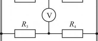
A voltmeter is a device whose purpose is to measure electromotive force (EMF) in a certain section of an electrical circuit, or more simply, a device for measuring voltage (electric potential difference). This device is always connected in parallel with the battery or load. The voltmeter displays the measured value in Volts.
If we talk about an ideal voltmeter, then it should have infinite internal resistance in order to accurately measure voltage and not have any side effects on the circuit. That is why in high-class devices they try to make the maximum possible internal resistance, on which the accuracy of measurement and the interference created by the voltmeter in the electrical circuit depend.
Figure - Voltage measurement formulas
If we talk about the installation method, voltmeters are divided into three main groups:
• Stationary;
• Panel;
• Portable;
As the name implies, stationary devices are used where constant monitoring is required, panel devices are used in distribution panels and on instrument panels, and portable devices are used in compact devices that can be used anywhere.
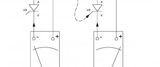
Figure - Voltmeter connection diagram
Watch a video about connecting a voltmeter:
According to their intended purpose, all voltmeters are divided
• Alternating current;
• Direct current;
• Selective;
• Phase sensitive;
• Pulse.
AC and DC voltmeters are used for measurements in networks with the appropriate type of current, but selective ones can separate the harmonic component of a complex signal and determine the root mean square value of the voltage.
Pulse voltmeters are commonly used to measure the amplitude of continuous pulse signals, and they are also capable of accurately determining the amplitude of a single pulse.
Phase-sensitive devices can measure changes in the components of complex voltages, making it possible to accurately study the amplitude-phase characteristics of amplifiers and other similar circuits.
Based on the operating principle, a distinction is made between electronic (digital or analogue) and electromechanical voltmeters (electromagnetic, thermoelectric, as well as magnetoelectric, electrodynamic and electrostatic).
All electromechanical devices, with the exception of thermoelectric ones, are essentially a conventional measuring mechanism with an indicating device. In all of them, additional resistances are used to expand the measurement limits.
Devices of this category, despite the rather high internal resistance, have a relatively large error, which makes it impossible to use them in experiments and research where increased data accuracy is required.
A thermoelectric voltmeter makes measurements using the electromotive force of one or more thermocouples, which heat up due to the incoming signal current. They are more accurate and compact compared to electromechanical voltage meters.
Electronic voltmeters, in turn, are divided into digital and analog.
A digital voltmeter converts a constant voltage value into a digital signal, which is displayed on the device display. This is done using an analog-to-digital converter.
In analog voltmeters, in addition to the magnetoelectric meter and additional resistors, there must be a measuring amplifier, which makes it possible to increase the internal resistance of the device several times and, accordingly, improve the accuracy of the readings.
Current measurement. Ammeter.
And let's start by measuring the current. The device used for these purposes is called ammeter , and it is connected in series to the circuit. Let's look at a small example:
As you can see, here the power supply is connected directly to a resistor representing the payload. In addition, the circuit contains an ammeter connected in series with a resistor. According to Ohm's law, the current strength in a given circuit is:
I = \frac{U}{R} = \frac{12}{100} = 0.12
We obtained a value equal to 0.12 A, which exactly coincides with the practical result shown by the ammeter in the circuit

