General information about measurements of electrical measuring instruments.
A measurement is a quantitative comparison of a measured physical quantity with its specific value, taken as a unit.
Measurements are made using measures and measuring instruments. Measures are samples of units of measurement (magazines of resistances, capacitances, scale bars, etc.). Electrical measuring instruments are devices used for direct or indirect comparison of a measured quantity with a measure. Direct comparison devices (ammeters, voltmeters, etc.) make it possible to determine the measured value directly from the instrument reading. Indirect comparison devices include bridges and compensators.
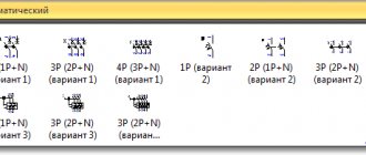
The classification of measuring instruments is carried out according to the type of measurement, principle of operation, measurement accuracy, and operating conditions. On the front side of the device are applied: scale and symbols indicating the purpose of the device, system, symbols of the type of current, voltage at which the device is tested, internal resistance or total deviation current, accuracy class, degree of protection of the device from external magnetic and electric fields, GOST , year of manufacture, operating conditions and a number of other quantities.
Tables 1 and 2 give an idea of the symbols on the scales of electrical measuring instruments.
Symbols on the scales of electrical measuring instruments.
| Instrument system | System sign | |
| Magnetoelectric | With mechanical counter force | |
| No mechanical counter force | ||
| Devices using a magnetoelectric system | Thermoelectric devices | With contact converter |
| With isolated converter | ||
| Electron tube devices | ||
| Photovoltaic devices | ||
| Electromagnetic | With mechanical counter force | |
| No mechanical counter force | ||
| Electrodynamic | Without steel | No mechanical counter force |
| With mechanical counter force | ||
| Ferrodynamic | With mechanical counter force | |
| No mechanical counter force | ||
| Induction | With mechanical counter force | |
| No mechanical counter force | ||
| Electrostatic | ||
| Thermal | ||
| Vibrating (reed) |
| D.C | — |
| AC single phase current | |
| Direct and alternating current | |
| Three-phase current (uniform load) | |
| Vertical arrangement of the device | ^ |
| Horizontal placement of the device | Õ® |
| Oblique (for example, at an angle of 60 0) | Ð60 0 |
| Accuracy class | 0,1;0,2; 0,5 |
| The insulation of the device is tested with a voltage of 2 kV | |
| Magnetic screen | ð |
| Rectifier |
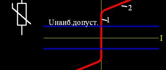
The most important characteristic of an electrical measuring instrument is accuracy. Depending on the accuracy, all electrical measuring instruments according to GOST 1845-59 are divided into eight classes: 0.05; 0.1; 0.2; 0.5; 1.0; 1.5; 2.5; 4. The accuracy class of the device determines the reduced error of the device
V %.
The reduced error is the ratio of the greatest absolute error of the device, expressed as a percentage.
X to the nominal value of his Khnom scale.
Nominal value Khnom. is called the upper limit of measurement of the device. Consequently, the accuracy class figure shows the magnitude of the possible relative error in percentage when the instrument needle deviates to the full scale.
How to use and connect an ammeter to a circuit?
To measure the current in a simple electrical circuit, we must break the circuit anywhere and connect a device to this gap (see Figure 5). This connection is called serial. That is, for example, to measure the current in a conductor, an ammeter is connected in series with this conductor - in this case, the same current flows through the conductor and the ammeter.
Rice. 5. Method of connecting an ammeter in an electrical circuit
In a circuit consisting of a current source and a series of conductors connected so that the end of one conductor is connected to the beginning of another, the current strength in all sections is the same. This follows from the fact that the charge passing through any cross-section of the conductors of the circuit in 1 s is the same. When there is current in an electrical circuit, charge does not accumulate anywhere in the conductors of the circuit, just as water does not accumulate anywhere in individual parts of a pipe when it flows through a pipe. Therefore, when measuring current, the ammeter can be connected to any place in a circuit consisting of a number of series-connected conductors, since the current at all points of the circuit is the same. If you connect one ammeter to the electrical circuit before the lamp, and the other after it, then both of them will show the same current strength.
Attention! You cannot connect an ammeter to the source terminals without some kind of current receiver connected in series with the ammeter. You can ruin the ammeter!
For each ammeter there is an upper limit of measurement (maximum current), that is, the ammeter scale shows what maximum current it is designed for. Including an ammeter in an electrical circuit with a higher current strength is unacceptable, as it may fail.
When turning on the device, it is necessary to observe the polarity, i.e., the terminal of the device must be connected only to the wire coming from the terminal with the “+” sign of the current source. When the device is turned on correctly, the electric current through the ammeter should flow from the “+” terminal to the “-” terminal.
When connected to a circuit, the ammeter, like any measuring device, should not affect the measured value. Therefore, it is designed in such a way that when it is connected to a circuit, the current strength in it almost does not change. As we already know, any electrical measuring instruments have a certain electrical resistance. When an ammeter is connected in series to an electrical circuit, its electrical resistance is added to the total electrical resistance of the electrical circuit. This causes an undesirable reduction in current. To prevent this from happening, the resistance of the ammeter must be low. The ideal would be an ammeter without resistance (R = 0), but in practice this is impossible to achieve.
The difference between variable and constant
First of all, DC voltage must be generated at substations with a relatively low voltage to be provided to the consumer (220V). However, when several devices are connected simultaneously, the total value increases. In this situation, to transmit voltage over long distances, it is necessary to use a thick and expensive cable. This is the only way to be able to transport current over long distances with minimal power losses.
In the AC example, the generated electricity is able to travel a long distance with minimal losses. Since 1980, it has become possible to rectify three-phase electric current and convert it back.
The main difference between AC voltage and DC current is that the latter shows comparative stability. By this we mean that it does not change the frequency of the direction of movement.
Healthy! The most common frequency in the world is 50 Hz.
Due to the fact that the movement of direct current flows more uniformly, the direction of electron flow is strictly in one direction. Moreover, the source in this situation has both a positive and a negative pole. Thus, direct current is mainly used in high-voltage lines (for transportation over long distances). After converting to a variable, it is transmitted to our sockets.
Interesting! Before the voltage reaches its destination (consumer), it enters the transformer. Here it is converted from high to lower, with a corresponding lower value, acceptable for use for domestic needs, and transmitted to the apartment or house.
Origin of alternating and direct current
A magnetic field near a wire causes electrons to flow in one direction along the wire because they are repelled by the negative side of the magnet and attracted to the positive side. Thus, the battery-powered DC power source was born, primarily thanks to the work of Thomas Edison.
Alternators gradually replaced Edison's DC battery system because alternating current is safer to carry over longer distances around town and can provide more power. Instead of constantly applying magnetism along a wire, scientist Nikola Tesla used a rotating magnet. When the magnet was oriented in one direction, electrons flowed toward the positive, but when the magnet's orientation was reversed, the electrons also turned.
Why is AC current dangerous for humans?
As already mentioned, a feature of AC voltage is the uniform flow of particles from one pole to the other. In comparison with DC current, it is considered less dangerous since in most cases it has a spasmodic effect on the human body. The spasm goes away immediately after the tension is relieved, which reduces the likelihood of critical results.
However, the absence of danger to the body is observed only in the case of a low value of direct current. The higher its value, the greater the likelihood of critical consequences. For example, when contacting voltages exceeding 500 V, current may be more dangerous than alternating current. However, in everyday life such values are absent and are used in transformers or substations, access to which is open only to specially trained people.
Important! The main difference between the effects of high-voltage current on a person is the strong knockback effect (compared to alternating current).
What is more dangerous for humans?
Variable AC poses a great danger to the human body. Under its influence, sharp fibrillation of the heart ventricles occurs. But this does not mean that direct current can be considered safe. People caught under such tension suffer severe injuries as a result of kickback and mechanical shock.
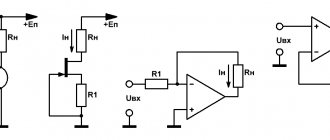
How to increase the measuring range of an ammeter?
In order to measure current as accurately as possible, we need to use an appropriate measuring range. An attempt to read values of several mA, when the scale covers measurements of up to 100 A, will end with us not even noticing the deviation of the ammeter needle.
Developers of ammeters use various technical solutions in order to be able to measure current in different ranges. In some cases, we can change the measuring range of the device ourselves. If we add an additional resistor to it (the so-called shunt), as shown in Fig. 6, we will be able to measure higher currents without subjecting the fragile structure of the ammeter to destruction.
Rice. 6. Extending the range of the magnetoelectric ammeter by adding a shunt resistor
Suppose we want to increase the ammeter's measuring range by n times . The total current I flowing through the device (Fig. 6) is then equal to n*IA . Then the equations of Kirchhoff’s first and second rules will be as follows:
- n ⋅ IA = IA + IB
- IB ⋅ RB = IA ⋅ RA
Therefore, the resistance of the shunt resistor can be calculated as follows:
RB = RA / (n-1)
For design reasons, the shunt resistor is used only for the magnetoelectric ammeter.
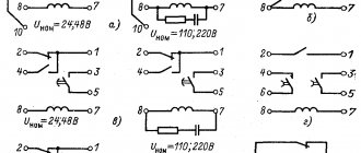
Graphic symbols of instrumentation on diagrams
Conventional graphic symbols of devices and automation equipment must comply with GOST 2.721 and the symbols given in the following table
All measuring and converting devices located locally (directly on the process equipment) are depicted on functional automation diagrams in the form of circles (if the circle does not fit alphabetic or digital designations, an oval is allowed).
If devices are placed on switchboards and consoles in central or local operator rooms, then a horizontal dividing line is drawn inside the circle.
If the function to which the circle corresponds is implemented in a computerized system, then the circle fits into a square (an oval into a rectangle).
In a simplified version of the construction, instruments and automation equipment that perform complex functions, for example, control, regulation, signaling and are made in the form of separate blocks, are represented by one symbol.
Requirements for the designation of instrumentation and automation devices on diagrams
In order to ensure the unity of notation systems, improve the readability of diagrams, and reduce errors during the installation of instruments and panels, it is necessary to strictly observe the correct designations of instrumentation devices. The requirements and rules for designating instrumentation devices on automation diagrams and wiring diagrams are determined by the following GOSTs:
- GOST 21.208-2013 Automation of technological processes
- GOST 21.404-85 System of design documentation for construction (SPDS). Automation of technological processes.
- GOST 2.303-68 Unified system of design documentation. Lines
- GOST 2.721-74 Unified system of design documentation. Conditional graphic designations in schemes.
- GOST 1.0-92 Interstate standardization system. Basic provisions
- GOST 1.2-2009 Interstate standardization system. Rules and recommendations for interstate standardization.