One of the parameters that characterizes the state of the electrical network is its power.
It reflects the amount of work performed by electric current per unit of time. The power of devices included in the electrical circuit must be within the power of the network. Otherwise, unpleasant surprises are possible - from equipment failure to short circuits and fires. The power of electric current is measured with a special device - a wattmeter. And if in a DC circuit it is calculated by simply multiplying the current by voltage (a voltmeter and an ammeter are sufficient), then in an AC network you cannot do without measuring equipment. They also control the operating mode of electrical equipment and take into account energy consumption.
Application of Wattmeters
The main area of application is the electrical power industry and mechanical engineering, electrical appliance repair shops. However, household meters are also widely used, which are purchased by lovers of electronics, computers and just ordinary people - to account for and save energy consumption.
Wattmeters are used for:
- Determining the power of devices;
- Testing of electrical networks and their individual sections;
- Testing of electrical installations (as indicating devices);
- Monitoring the operation of equipment;
- Accounting for electricity consumption.
Cosine phi and reactive load
For example, my homemade simple power supply, connected to the network and not feeding any load, still consumes energy, since it is a transformer. The voltage goes directly to the primary winding of the transformer.
It should not be left plugged in, as it still consumes at least a little current.
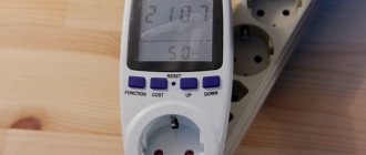
I turn on my transformer power supply to a 220 Volt network. So, the voltage in the outlet is 236.8 Volts:
I connected a 12 volt light bulb to the power supply. In total, our loaded power supply consumes 0.043 Amperes.
Power Factor - power factor, also known as cosine phi. Now it is equal to 0.42, since the load is inductive.
We check this whole thing using the formula P=IUcos φ=0.043x236.8x0.42=4.28 Watt. Almost everything agrees with a small error.
Types of wattmeters
Power measurement is preceded by measuring the current and voltage of the test section of the circuit.
Depending on the methods of measurement, data conversion and display of final information, wattmeters are divided into analog and digital.
Analog wattmeters are either indicating or recording and reflect the active power of a circuit section. The display of the indicating device has a semicircular scale and a rotating arrow. The scale divisions are graduated according to specific power values, measured in watts (W).
Digital wattmeters measure both active and reactive power. In addition, the device display can also display (in addition to power readings) current, voltage, and energy consumption over time. Measurement data can be displayed remotely on the operator’s computer.
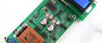
Video about a wattmeter from China:
DC Power Measurement
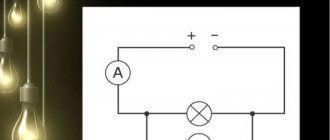
Due to the lack of reactive and active components in DC circuits, a wattmeter is very rarely used to measure power. As a rule, the amount of energy consumed or supplied is measured by an indirect method; the current I in the circuit is measured using a series-connected ammeter, and the load voltage U is measured using a parallel-connected voltmeter. Then, using the simple formula P=UI, the power value is obtained.
To reduce the measurement error due to the influence of internal resistances of devices, devices can be connected using various circuits, namely, with a relatively low load resistance R, the following connection circuit is used:
And for a large value of R, such a scheme:
Device and principle of operation
Analog wattmeters
The most common and accurate analog wattmeters are electrodynamic system devices.
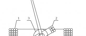
The operating principle is based on the interaction of two coils. One of them is stationary, has a thick winding with a small number of turns and low resistance. Connected in series with the load. The second coil is movable.
Its winding is made of thin wire and has a large number of turns, so its resistance is high.
It is connected in parallel to the load and is equipped with additional resistance (to prevent a short circuit between the coils).
When the device is connected to the network, magnetic fields are formed in the coils. Their interaction creates a torque that deflects the moving coil with the arrow connected to it at a certain angle.
The magnitude of the angle is equivalent to the product of current and voltage at a given time.
Digital wattmeters
The operation of a digital wattmeter is based on a preliminary measurement of current and voltage. To do this, the following are installed at the input: in series with the load - a current sensor, in parallel - a voltage sensor. They can be based on thermistors, instrument transformers, thermocouples and other elements.
The instantaneous values of the obtained current and voltage values are transmitted through an analog-to-digital converter to the built-in microprocessor. Here the necessary calculations are made (active and reactive power is found) and are presented as final information on the display and connected external devices.
Figure - Wattmeter connection diagram
Power measurement in three-phase AC circuits
As in single-phase networks, also in three-phase networks, the total energy of the network can be measured by an indirect method, that is, using a voltmeter and ammeter according to the diagrams shown above. If the load of the three-phase circuit is symmetrical, then the following formula can be applied:
Ul – linear voltage, I – phase current.
If the phase load is not symmetrical, then the power of each phase is summed up:
When measuring active energy in a four-wire circuit using three wattmeters, as shown below:
The total energy consumed from the network will be the sum of the wattmeter readings:
The method of measuring with two wattmeters has also become equally widespread (applicable only for three-wire circuits):
The sum of their readings can be expressed by the following expression:
For a symmetrical load, the same formula applies as for total energy:
Where φ is the shift between current and voltage (phase shift angle).
The reactive component is measured according to the same scheme (see figure c)) and in this case it will be equal to the algebraic difference between the instrument indicators:
If the network is not symmetrical, then to measure the reactive component, two or three wattmeters are used, which are connected according to different circuits.
Connecting a Wattmeter
Wattmeters have four terminals (2 inputs, 2 outputs) for connection. Two of them are used when assembling a serial (current) circuit - it is connected first, and two - for a parallel (voltage circuit).
The beginning of the voltage circuit (input) is connected to the beginning of the current circuit (connect the terminals with a jumper), connected to one terminal of the network. The end of the voltage circuit (output) is connected to another terminal of the network.
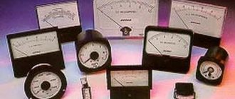
Let's consider several wattmeters of different designs and different manufacturers:
Multifunctional digital wattmeter CM3010 accuracy class 0.1
Designed to measure active power, current, voltage and frequency in DC circuits and single-phase AC circuits; for testing wattmeters, ammeters, voltmeters of class 0.3 and below, frequency meters of class 0.01 and below.
Current measurement limits Iп:
- on direct and alternating current: 0.002-0.005-0.01-0.02-0.05-0.1-0.2-0.5-1-2-5-10 A.
Voltage measurement limits Up:
- DC: 1-3-7.5-15-30-75-150-300-450-700-1000 V.
- alternating current: 1-3-7.5-15-30-75-150-300-450-700 V.
Power measurement limits respectively Up* Iп
Frequency measurement limits are from 40 to 5000Hz.
Basic error:
- reduced error in measuring current, voltage and power at direct current ±0.1%;
- reduced error in measuring current and voltage on alternating current in the frequency range from 40 to 1500 Hz ±0.1%;
- reduced error in measuring power on alternating current in the frequency range from 40 to 1000 Hz ±0.1%;
- relative frequency measurement error in the frequency range from 40 to 5000 Hz ±0.003%;
Overall dimensions 225x100x205 mm. Weight no more than 1 kg. Power consumption no more than 5W.
Multifunctional wattmeters SM3010 are produced according to TU 4221-047-16851585-2014, comply with the requirements of TR TS 004/2011, TR TS 020/2011.
Manufactured by ZIP-Nauchpribor.
Measuring devices TsP8506-120 (hereinafter referred to as devices).
Designed to measure active, reactive, active and reactive three-phase three-wire AC circuits, display the current value of the measured power on a digital indicator and convert it into an analog output signal (hereinafter referred to as the output signal).
The measured values are displayed digitally on built-in indicators. The measured values are displayed on digital indicators in units of the measured value supplied directly to the input of the device, or in units of the measured value supplied to the input of current and voltage transformers, taking into account transformation ratios, in watts, kilowatts, megawatts, vars, kilovars, megavars. Digital indicators have four significant digits.
Purpose of CPU8506-120:
- for measuring active and reactive power in three-phase three-wire electrical circuits of alternating current with a frequency of 45 to 55 Hz
Brief technical specifications of CPU8506-120 (Wattmeter)
Panel digital three-phase varmeter:
- Power factor: for a wattmeter cos φ=1, for a varmeter sin φ=1
- Overall dimensions: 120x120x150 mm
- Sign height: 20 mm
- Maximum display range: 9999
- Accuracy class: 0.5
- Conversion time: no more than 0.5s
- Operating temperature: +5 ... +40 degrees C (O4.1), -40 ... +50 degrees C (UHL3.1)
- Front panel protection degree: IP40
- Power consumption: 5VA
- Weight: no more than 1.2 kg
General information
When designing devices, you need to be able to correctly calculate the power of electrical equipment. This is necessary, first of all, for long-term operation of the device. If a product is subject to wear and tear, it may fail immediately or over a period of time.
This option is considered unacceptable, since there are types of equipment that must work without failure (artificial respiration apparatus, monitoring the level of methane in a mine, and so on), since human life depends on it. The main characteristics of electrical energy include the following: power, current, voltage (potential difference) and electrical conductivity (resistance) of materials.
Consumer power
Power should not be confused with electrical energy. The first unit of measurement is the watt (W), the name of which comes from the name of the famous physicist James Watt. The physical meaning of 1 W is the consumption of electrical energy per unit of time equal to 1 second (1 W = consumption of 1 joule per 1 second). There are derived units of measurement: milliwatt (1 mW = 0.001 W), kilowatt (1 kW = 1000 W), megawatt (1 MW = 1000 kW = 1000000 W), gigawatt (1 GW = 1000 MW = 1000000 kW = 1000000000 W) and etc. To measure electrical energy, special meters are used, and its unit of measurement is Wh.
Watt can be associated with some physical quantities: 1 W = 1 J/s = (1 kg * sqr (m)) / (c * sqr (c)) = 1 N * m/s = 746 l. With. The last numerical value is called electrical horsepower. Wattmeter - electrical power meter. However, its value can be determined in another way. To do this, one should analyze the physical quantities on which it depends.
Current strength
The amount of electrical charge that passes through a conductive material per unit time is called electric current. The quantity is abbreviated as amperage or current. It is denoted by the letters “I” or “i” and has a direction (vector quantity). The current is measured in amperes (A). There are also derived units formed using prefixes: 1 mA = 0.001 A, 1 kA = 1000 A, and so on. You can measure its value with an ammeter. To do this, it must be connected in series to an electrical circuit.
The physical meaning of a current of 1 A is the passage of an electric charge of 1 C (coulomb) in 1 second through the cross-sectional area S. 1 coulomb contains approximately 6.241 * 10^(18) electrons.
Current in scientific interpretation is classified into direct and alternating. The first type does not change its direction per unit time, but its amplitude values can change. The direction and amplitude of the alternating current changes according to a certain law (sinusoidal and non-sinusoidal). The main parameter is its frequency. The type of alternating current is determined using an oscilloscope.
Electrical voltage
From the physics course we know that every substance consists of atoms that have a neutral charge. They are made up of subatomic particles. These include the following: protons, electrons and neutrons. The first ones have a positive charge, the second ones have a negative charge, and the third ones are not charged at all.
The total charge of protons compensates for the charge of all electrons. However, under the influence of external forces, this equality is violated, and the electron “breaks out” from the atom, which already has a positive charge. It attracts an electron from a neighboring atom, and the process is repeated until the energy is minimal (less than the energy of “pulling out” the electron).
During interatomic interaction, an electromagnetic field with negative or positive components is formed. The difference between two points of oppositely sign components is called electrical voltage. The work done by an electromagnetic field to move a point electric charge from point A to point B is called potential difference. The physical meaning of voltage (U): a potential difference of 1 V between two point charges of 1 C, the movement of which requires the energy of an electromagnetic field equal to 1 J.
The unit of measurement is volt (V). You can determine the value of the potential difference using a voltmeter, which is connected in parallel. The following are considered derived units of measurement: 1 mV = 0.001 V, 1 kV = 1000 V, 1 MV = 1000 kV = 1000000 V, and so on.
Electrical circuit resistance
The electrical conductivity of a material depends on several factors: electronic configuration, type of substance, geometric parameters and temperature. Information about the electronic configuration of a substance can be obtained from D. I. Mendeleev’s periodic table. According to this information, substances are:
- Conductors.
- Semiconductors.
- Dielectrics.
The first group includes all metals, electrolytes (solutions that conduct current) and ionized gases. The carriers of electric charge in metals are electrons. In solutions, their role is played by ions, which can be positive (anions) and negative (cations). Free electrons and positively charged ions are considered free carriers of charged particles in gases.
Semiconductors conduct electricity only under certain conditions. For example, when exposed to external forces. Under their influence, the Coulomb bonds between the electron and the nucleus decrease. In this case, the negatively charged particle “breaks out”. In its place, a “hole” is formed with a positive charge. It attracts a neighboring electron, tearing it away from the atom. As a result, the movement of electrons and holes occurs. Insulators or dielectrics do not conduct electricity at all. These include materials without free charge carriers, as well as inert gases.
In conductors, as the temperature increases, the resistance value increases. In this case, destruction and distortion of the crystal lattice occurs. Charged particles collide (interact) with atoms and other particles of material. As a result, their movement slows down, but then resumes again under the influence of the electromagnetic field. The process of this “interaction” is called electrical conductivity of the substance. However, in semiconductors, this value decreases with increasing temperature. The geometry of materials includes the following: length and cross-sectional area.
Resistance is measured in Ohms (Ohm) using an ohmmeter, which is connected in parallel to a section of the circuit or radio component. There are derived units of measurement: 1 kOhm = 1000 Ohm, 1 MOhm = 1000 kOhm = 1000000 Ohm.