In electrical networks, the appearance of pulsed voltage surges caused by various reasons is quite often observed. Despite the fact that such overvoltages are short-term in nature, they can cause insulation breakdown followed by a short circuit. One option to prevent negative consequences would be to use more reliable insulation, but this method significantly increases the cost of all equipment. Therefore, arresters became the most optimal option. The main function of these devices is to limit overvoltages in electrical networks and installations.
1. Arrester, its purpose, principle of operation
Arresters are protective devices. They are designed to protect the insulation of electrical equipment from overvoltages. The arrester consists of two electrodes and an arc extinguishing device.
One of the electrodes is fixed to the protected circuit, the second electrode is grounded. The space between these two electrodes is called the spark gap. At a certain voltage value between the electrodes, the spark gap breaks through and removes the overvoltage from the protected section of the circuit.
After a breakdown by a pulse, the spark gap becomes sufficiently ionized so that the phase voltages of the normal mode can break through, and therefore a short circuit occurs. The task of the arc extinguishing device is to eliminate this in the shortest possible time before the protection devices operate.
Operating principle of arresters. The design of the arresters provides an air gap in the jumper, which connects the phases of the power line and the grounding loop. At the nominal voltage value, the circuit in the jumper is broken. In the event of a lightning discharge as a result of overvoltage in the power line, a breakdown of the air gap occurs, the circuit between the phase and the ground is closed, and the high voltage pulse goes directly into the ground.
Types/Classification
There are three main types of surge suppressors:
- Tubular arresters
- Valve arresters (originally non-linear resistor type with spark gaps, currently silicon carbide type without spark gaps)
- Surge arresters - nonlinear surge suppressors (metal oxide type without spark gaps)
There are four (4) classes of arresters:
- Station class
- Intermediate class
- Distribution class (high, medium and low load)
- Helper class
Of the three types of arresters mentioned above, the tubular type is no longer used. Nonlinear resistor-type valve arresters with spark gaps were used in the mid-1970s and have now also been discontinued. The traditional type with silicon carbide blocks/discs is still used today. Today, metal oxide surge suppressors without spark gaps are the most widely used. In this article we are not covering the helper class.
Of the four classes of arresters discussed in this article, station-grade arresters are the best considering their cost, durability, and overall quality of protection. It has the lowest (best) protection level and discharge energy compared to the higher (worse) protection levels of other classes. As stated above, the distribution class has several load levels. High performance arresters are more durable and have lower protection characteristics. The body of such a spark gap can be polymer or porcelain.
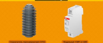
We will focus on non-spark gap metal oxide surge arresters (MOS) as they are the most reliable and performant. Please note that both spark gap and non-spark arresters serve the same purposes and the process for selecting and using them is similar. However, the need to use higher voltage levels for valve-type arresters and the possibility of spark gap contamination means that the degree of protection and reliability will be somewhat lower. If valve arresters fail, the reader should consider replacing them with metal oxide surge arresters without spark gaps.
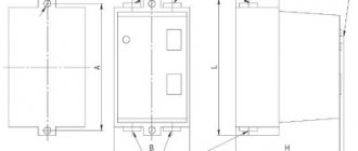
Gas arrester
Gas arresters are components filled with an inert gas (Fig. 2). The arrester body is made in the form of a ceramic tube, the ends of which are closed with metal plates and act as electrodes.
Figure 2 – Block diagram of a gas discharger
Arc extinction methods
Ensuring that the arc is extinguished in a given period of time can be achieved by using a special gas that suppresses the electric arc when the current is below a threshold value. But in practice, this method is rarely used; the disadvantage of such arresters is the low stability of the service life. That is, the number of possible operations can only be determined approximately in advance.
Selection of arresters
The main parameters of arresters: capacity class, longest permissible operating voltage, levels of remaining voltages during switching and lightning impulses, rated voltage, magnitude of the response current of the anti-explosion device, rated discharge current, leakage distance of external insulation.
The choice of arresters is made based on the purpose, design, required level of overvoltage limitation, network diagram and its parameters.
conclusions
Spark gaps are used as inexpensive, reliable devices that can withstand heavy loads. In telecommunications applications, the use of varistors is limited due to their high capacitance. At the same time, the feasibility of their use largely depends on economics. The valve arrester is an expensive device that requires replacement every 20 operations. The cost difference between solid-state and valve-type arresters is completely offset by higher operating costs, so a solid-state arrester is preferable.
9. Technical characteristics of arresters
The following main technical characteristics of arresters are distinguished:
- Circuit voltage class;
- Highest permissible voltage;
- Breakdown voltage at a frequency of 50 Hz in dry conditions and in the rain;
- Pulse breakdown voltage at pre-discharge time from 2 to 20 μs;
- Remaining voltage at 8 µs wave;
- Leakage current;
- Current carrying capacity;
- Creepage distance of external insulation;
- Permissible wire tension;
- Height;
- Limiter weight.
Standards/Rules
Surge suppressors are developed and tested in accordance with GOST 16357-83 - AC valve arresters and GOST R 52725-2007 - Non-linear surge suppressors (NSS) for AC electrical installations with voltages from 3 to 750 kV (ANSI/IEEE: ANSI/IEEE C62. 1 - standard for AC valve arresters with spark gaps, as well as ANSI / IEEE C62.ll - standard for non-linear surge suppressors for alternating current electrical installations). Article 280 of the NFPA70/National Electrical Code regulates the basic requirements for surge suppressors, as well as the rules for their installation and connection. In addition, surge suppressors are listed under the Surge Suppressor (OWHX) category by the US Labor Safety Laboratory, as well as other nationally recognized testing laboratories in the relevant sections of the above ANSI/IEEE standards.
11. Arresters 6 kV, 10 kV, 35 kV, 110 kV, 220 kV
The main characteristics of 6-220 kV arresters are given in tables 2 and 3.
Table 2 - Technical characteristics of 6 kV, 10 kV arresters
| Parameter | Unit | RVO-6 N | RVO-10 N |
| Mains voltage class | kV | 6 | 10 |
| Highest permissible voltage | kV | 7,5 | 12,7 |
| Breakdown voltage at a frequency of 50 Hz in dry conditions and in the rain: | |||
| no less | kV | 16 | 26 |
| no more | kV | 19 | 30,5 |
| Pulse breakdown voltage at pre-discharge time from 2 to 20 μs, no more | kV | 32 | 48 |
| Remaining voltage at a wave of 8 μs, no more: | |||
| with current amplitude 3000A | kV | 25 | 43 |
| with current amplitude 5000A | kV | 27 | 45 |
| Leakage current, no more | µA | 6 | 6 |
| Current carrying capacity: | |||
| 20 current pulses with a wave of 16/40 µs | kA | 5,0 | 5,0 |
| 20 square wave current pulses with a duration of 2000 µs | A | 75 | 75 |
| Leakage distance of external insulation, not less | cm | 18 | 26 |
| Permissible wire tension, not less | N | 300 | 300 |
| Height, no more | mm | 294 | 411 |
| Weight, no more | kg | 3,1 | 4,2 |
Table 3 - Technical characteristics of 35 kV, 110 kV, 220 kV arresters
| Parameter | Unit | RVS-35 RVS-35 T1 | RVS-110M RVS-110M T1 | RVS-220M RVS-220M T1 |
| Mains voltage class | kV | 35 | 110 | 220 |
| Highest permissible voltage | kV | 40,5 | ||
| Breakdown voltage at a frequency of 50 Hz in dry conditions and in the rain: | ||||
| no less | kV | 78 | 200 | 400 |
| no more | kV | 98 | 250 | 500 |
| Pulse breakdown voltage at pre-discharge time from 2 to 20 μs, no more | kV | 125 | 285 | 530 |
| Remaining voltage at a wave of 8 μs, no more: | ||||
| with current amplitude 3000A | kV | 125 | 315 | 630 |
| with current amplitude 5000A | kV | 130 | 335 | 670 |
| Leakage current, no more | µA | 143 | 367 | 734 |
| Current carrying capacity: | ||||
| 20 current pulses with a wave of 16/40 µs | kA | 10,0 | 10,0 | 10,0 |
| 20 square wave current pulses with a duration of 2000 µs | A | 150 | 150 | 150 |
| Leakage distance of external insulation, not less | cm | 115 | 345 | 690 |
| Permissible wire tension, not less | N | 300 | 500 | 500 |
| Height, no more | mm | 1280 | 3100 | 4620 |
| Weight, no more | kg | 73 | 175 | 497 |
Temporary overvoltages
Temporary overvoltages can be caused by numerous problems in the system, such as switching overvoltages, single-phase ground faults, load shedding and ferroresonance. To determine the most likely forms and causes of temporary overvoltages, it is necessary to evaluate the system characteristics and normal operating conditions. If detailed studies of temporary processes in the system and calculations are not available, it is permissible, at a minimum, to estimate the overvoltage due to a single-phase short circuit to ground. Information about the system grounding configuration and its components will help identify overvoltages associated with a single-phase ground fault. The reader can find guidance on determining the magnitude of overvoltage associated with a single-phase ground fault in ANSI 62.22, which governs the use of surge suppressors. The main result of the effect of temporary overvoltages on metal oxide surge arresters is an increase in current and power dissipation, as well as an increase in the temperature of the arrester.
The arrester's ability to withstand temporary overvoltages must meet or exceed the expected temporary overvoltages in the system.
Table 3 below defines the transient surge resistance of all GE arrester models per MCOV. The table shows the maximum duration and magnitude of temporary overvoltage that can be applied to the arrester before the voltage must be reduced to acceptable operating values. The resistance to temporary overvoltages is determined independently of the system resistance and is valid for the voltages applied at the location where the arrester is installed.
| Resistance to temporary overvoltage of General Electric arresters | ||||||
| Duration (seconds) | Previous load* | Polymer (per MCOV unit) | Porcelain (per MCOV unit) | |||
| Execution of "normal duty" | "Riser Pole" performance | Performance "Intermediate" | Version Power station | Version Ultra-high voltage power plant (396 - 612 kV) | ||
| 0.02 | No | 1.75 | 1.58 | 1.58 | 1.61 | 1.56 |
| 0.1 | No | 1.64 | 1.52 | 1.52 | 1.55 | 1.52 |
| 1 | No | 1.57 | 1.43 | 1.43 | 1.47 | 1.45 |
| 10 | No | 1.49 | 1.37 | 1.37 | 1.39 | 1.38 |
| 100 | No | 1.43 | 1.32 | 1.32 | 1.34 | 1.32 |
| 1000 | No | 1.35 | 1.29 | 1.29 | 1.30 | 1.25 |
| 10000 | No | — | 1.27 | 1.27 | 1.28 | 1.18 |
| 0.02 | Yes | 1.73 | 1.56 | 1.56 | 1.56 | 1.49 |
| 0.01 | Yes | 1.62 | 1.49 | 1.49 | 1.50 | 1.45 |
| 1 | Yes | 1.55 | 1.41 | 1.41 | 1.42 | 1.38 |
| 10 | Yes | 1.47 | 1.35 | 1.35 | 1.36 | 1.32 |
| 100 | Yes | 1.40 | 1.31 | 1.31 | 1.32 | 1.26 |
| 1000 | Yes | 1.33 | 1.28 | 1.28 | 1.28 | 1.19 |
| 10000 | Yes | — | 1.27 | 1.13 | ||
*Previous load levels are determined according to Table 4