Microchip PIC18F252
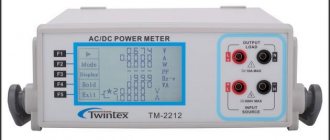
Everyone has probably ever thought about the question of how much a particular household electrical appliance consumes. For example, how much energy does a TV consume in standby mode? How does the energy consumption of a refrigerator change in different operating modes? For these purposes, you will need an AC wattmeter, and in the article we will look in detail at the design of one of the device options (Figure 1).
| Picture 1. | Digital AC wattmeter. |
It makes no sense to develop such devices for direct current due to the fact that in this case everything is very simply calculated using known laws and mathematical formulas, and only an ammeter is required from the measuring instruments. For alternating current, everything is a little more complicated and previously analog wattmeters for alternating current, although they provided high accuracy, were difficult to manufacture, not to mention digital wattmeters and the ability to assemble such devices at home. Modern technologies and element base make it possible to design multifunctional devices at minimal cost. Cheap microcontrollers (MCUs) with rich peripherals and powerful computing capabilities significantly simplify the creation of various automation and control systems. Integrated precision analog peripherals, and in some microcontrollers a digital signal processing subsystem, make it possible to develop multifunctional measuring instruments.
The digital wattmeter, the design of which we will consider, is designed to measure the power consumption of devices connected to an alternating voltage network of 207 - 235 V / 50 Hz. The main element of the wattmeter is an 8-bit PIC microcontroller from Microchip PIC18F252 series, which, using external ADCs, measures the current flowing through the load, the voltage across the load, calculates the effective value of the voltage (effective value) in the network, the effective value of the current and the average value of power consumption. All specified parameters are displayed on a two-line character LCD indicator.
The device does not have a separate power source. A built-in mains power supply is used, due to which the microcontroller part of the device is completely isolated from analog nodes that are under mains voltage.
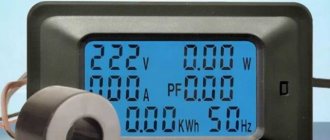
marazmPRO2 › Blog › Wattmeter 60V 100A from China
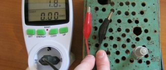
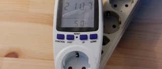
We will talk about a Chinese measuring device, calling it a wattmeter is not entirely correct, because the device is multifunctional and measures not only watts, but also amperes, watt/h, ampere/h... The device is essentially a multimeter that measures everything at once
. and in addition to measurements, it makes calculations of energy consumption and can accurately calculate the battery capacity (both when charging and discharging).
The wattmeter is connected to an open DC circuit with a voltage of up to 60 Volts and is capable of passing through itself a huge current of up to 100 Amperes (I briefly passed more than 300 A, but the device turns off at this current), often such a current cannot be measured with a conventional multimeter (tester), you can, of course, use current clamps with the function of measuring direct current (I have a Mastech MS2108) but then the measurement accuracy will not be great.
So, as I said, the device must be connected in series to the circuit between the voltage (current) source and the consumer.
SOURCE side
— current source connection side (input)
LOAD
— load connection side (output)
The sides are labeled on the device itself, but the wires are not marked in any way and, moreover, are of an indecently short length.
I solved the problem immediately by disassembling the case and resoldering the wires into longer ones and making crocodiles at the ends for convenience (there is no photo, but everything can be seen in the video)
First of all, I use this device to measure the capacity of batteries. Sometimes this is the only way to determine the residual capacity of an old battery and understand how much Ah it has lost over its service life. Also, based on the ammeter readings, you can immediately determine whether the battery is charging or the charging process has already been completed and the charging current has dropped to zero or the charging process has not even begun. During the use of the device, five batteries were restored and two were given a disappointing diagnosis. In addition to measuring the capacity of the battery, I use the device to check the true power of certain devices, for example the same Chinese lamps or power supplies... a couple of times I even returned money for St. diode lamps that did not match the power from the description.
The device also has the function of recording all maximum values, but does not have the function of turning off the load when the power supply voltage drops. This would be convenient when discharging the battery and checking it for residual capacity, but you have to “catch” the lower value of the battery voltage (usually 10V) so as not to subject the battery to a deep discharge. Also, the device does not have a timer, so you need to time it yourself.
The only disadvantages I can mention are the short wires, which are inconvenient to connect, and probably the absence of any fuse. The fact is that there were cases when, through negligence, I shorted the load wires, thereby creating a short circuit with a current of 300A (the source was a 70A/h battery), the wires burned and thought that everything was ruined by the device, but partly when the short circuit was eliminated, the device rebooted and continued to please with its trouble-free operation, but still it would not hurt to have some kind of fuse.
Schematic diagram
The circuit diagram and PCB design were developed in the free SoloPCB tools design environment. The schematic diagram of the device is shown in Figure 2. A complete list of components used is given in Table 2.
| Figure 2. | Schematic diagram of a digital AC wattmeter. |
To calculate power consumption, we need to know the voltage across the load and the current consumed by the load. The voltage to be measured is the AC mains voltage, so it must be taken into account that it can be in the range of 207 V - 253 V. In order to increase the accuracy of measurements, it is necessary to measure the mains voltage, rather than using a fixed average value of 230 V in calculations .
The mains power lines are connected to connector J1 (AC IN, AC input). The analog node for measuring network voltage consists of a resistive divider (R1, R2 R3), a precision reference voltage source (U3) and an ADC (U5). A resistive divider connected between phase and neutral is designed to reduce voltage scaling with a coefficient of R1/(R1+R2+R3)=1/201. This way we reduce the ±320V peak voltage to ±1.59V. We then use the REF03 (Analog Devices) voltage reference to offset this voltage up by 2.5V so that the ±320V range matches the input range ADC 0.91 V – 4.09 V.
Microcontroller program
As we noted above, the microcontroller reads voltage and current values every 1 ms and accumulates 40 measurements of each parameter, which corresponds to two periods for a frequency of 50 Hz. The RMS values and power consumption are then calculated. The 1 ms period is generated using the built-in Timer A, operating in 16-bit mode with an overflow interrupt signal.
After receiving all samples, the effective (rms) values of voltage and current are calculated using the formula:
It should be noted that the resulting samples also contain the phase relationship between voltage and current. Thus, the AC active power, which is calculated by the formula (V×I×cosθ), can be obtained by calculating the average power using the following formula:
All calculated values are displayed on the LCD indicator screen. To work with the indicator, the lcd.h library for the CCS C compiler is used.
| Figure 6. | Measuring the power consumption of a soldering station using a digital wattmeter. |
| Figure 7. | Measuring the power consumption of a 2 kW water heater. |
List of components used
| Designation in the diagram | Name, denomination | Housing, note |
| U1, U2 | 78L05 | SOT-89 |
| U3 | REF03 | SO-8 |
| U4 | ACS712-20A | SO-8 |
| U5, U10 | MCP3202-BI/SN | SO-8 |
| U6, U7, U8 | HCPL-0630 | SO-8 |
| U9 | PIC18F252-I/SO | SO-28 |
| BR1, BR2 | Diode bridge DF08S | 800 V / 1 A |
| TR1 | Transformer HR-E3013051 | 2 × 6 V, 1.5 VA |
| LCD1 | TC1602D | Two-line LCD indicator |
| C1, C18 | 470 µF 25 V | 10 mm × 10 mm |
| C2, C17 | 100 µF 16 V | 6.3 mm × 5.4 mm |
| C11, C12 | 22 pF 50 V | smd 0805, ceramics |
| C9 | 1 nF 50 V | smd 0805, ceramics |
| C2, C4, C5, C6, C7, C8, C10, C13, C22, C14, C15, C16, C17, C20 | 100 nF 50 V | smd 0805, ceramics |
| C21 | 1 µF 25 V | smd 1206, ceramics |
| R16 | 0 ohm | smd 0805, 1% |
| R2, R3 | 1 MOhm | |
| R5, R6, R17 | 1 kOhm | |
| R1, R14, R15, R18, R19 | 10 kOhm | |
| R7, R8, R9, R13 | 2.5 kOhm | |
| R4, R10, R11, R12 | 330 Ohm | |
| D2, D3 | Red LED | smd 0805 |
| D1 | Schottky diode SS14 | 1 A / 40 V, SMA housing |
| Y1 | Quartz crystal 20 MHz | |
| F1 | Fuse holder | Surface Mount |
| J1, J2 | Screw terminal block 1×3 | pitch 5.2 mm |
| J3 | Pin connector 1x5 | pitch 2.5 mm |
Printed circuit board
The PCB design was also done in the SoloPCB environment. Designing the instrument as a portable device was a good idea, with the PCB outline being designed in Autocad and then exported to the SoloPCB environment (Figure 5).
| Figure 5. | View of the digital wattmeter printed circuit board project in the SoloPCB environment. |
The printed conductors of the power lines (phase, neutral, ground) connecting the input (AC IN) and output (AC OUT) connectors are made as wide as possible, all blocking capacitors are located as close as possible to the microcircuits. The analog (AGND) and digital ground (DGND) buses are separate. All components are located on the top layer.
Note:
When designing the circuit and PCB in the SoloPCB environment, some elements that were missing in the libraries were created manually. A library of these elements is included in the archive with project files, which you can download in the downloads section.
DIAGRAM OF A SIMPLE WATTMETER
If you need to make a device to measure the power consumption of household appliances. It is not necessary to complicate the circuit with microcontrollers, LCD indicators and other expensive radio components. This design doesn't even require transistors. It is enough to feed part of the current from the consumer through a small transformer to a diode rectifier, and then to a dial indicator, in order to have a fairly accurate power indicator up to 1 kilowatt. If necessary, you can increase this range to at least 10 kW.
AC Power Meter
The basis of the device’s operation is a current transformer, which is essentially the same as a regular transformer. One winding consists of 3000 turns of thin wire wound on an iron core - this is the secondary winding. The primary winding is a pair of turns of the power cord. The ratio of current flowing through the primary side and the secondary winding is the inverse ratio of the number of turns. The linearity will not be ideal, but it will be good for average accuracy. In the end, whether the device consumes 540 watts or 580 is not very important. The half-wave rectifier consists of a small capacitor and germanium diodes; the forward voltage drop during the transition is measured by a 100 μA indicator. You can select the measurement limit of 1000 W and 100 W by connecting a resistor in parallel with the pointer head.
During testing and adjustment (selecting resistance), a 100 W incandescent lamp and a 500 W spotlight were used. That is, connect a load whose power you know in advance, and use it to set the required indicator readings. The finished wattmeter can be placed in any plastic box, or built into a surge protector. In this case, you will need to find a small switch, such as a recording level indicator from an old tape recorder.
Originally posted 2019-04-16 17:00:44. Republished by Blog Post Promoter
Source
Measuring device connection diagram
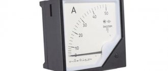
The accuracy of the data obtained will depend on how correctly the wattmeter is connected in a particular section of the circuit. The correct circuit for connecting a wattmeter is as follows: the fixed current coil of the measuring device is connected in series to the load or electricity consumers.
The moving voltage coil is connected in series with an additional resistance, and then this entire section is connected in parallel to the load. The moving part of the wattmeter has a certain angle of rotation, calculated by the formula: α = k2IхIu = k2U/Ru, in which I and Iu are the currents of the serial and parallel coils of the device, respectively.
Since the circuit uses additional resistance, the parallel circuit of the device will have an almost constant resistance (Ru). In this case, the rotation angle will be equal to: α = (k2/Ru)хIхU = k2IхU = k3P. That is, the power of the circuit will be determined precisely by this parameter.