A device with a display based on a cathode ray tube, designed to study the time parameters and amplitude of an electrical signal, is called an oscilloscope. The signal is sent to the input of the device, the result is recorded on a photo tape or displayed on the screen. It heads the top of the most necessary devices used for setting up and adjusting electronic circuits.
What does an oscilloscope look like?
Oscilloscope and its functions
This is an electronic device on the screen of which the waveform is observed. A number of options are available during operation:
- recording instantaneous characteristics;
- analogy of phase shifts and signal shapes with other pulses;
- control and monitoring of sinusoidal, triangular and square waves;
- pulse sweep to measure rise time.
Simply put, this is a television receiver where the electrical signal is monitored visually. Knowing the principles of operation and the circuit diagram of the device, they assemble the oscilloscope with their own hands.
Devices can be classified according to the following indicators:
- features of work and purpose;
- number of signals viewed at once;
- method of information processing;
- type of playback device.
According to the features of the work, they are divided into models: high-speed, stroboscopic, universal, memory and special. The number of simultaneously sent signals is one, two or more.
Important! Multichannel n-oscilloscopes display n-graphs on the screen, reading readings from the n-th number of signal inputs.
Analog and digital devices share methods for processing the received information. Signal display units are represented by cathode ray tubes (CRTs) or matrix panels.
Software
The hardware is ready, now you need to prepare the software environment to see the measurement results on the computer screen. Fortunately, today there are many programs that work with oscilloscopes.
Modern utilities are equipped with all the necessary functions for studying and analyzing the signals with which the oscilloscope works.
Circuit of a simple oscilloscope
To understand how the device works, study the standard block diagram.
Block diagram of an oscilloscope
Oscilloscope - concept and design of the device
Two types of beam deflection are involved in the formation of a signal on the screen: vertical and horizontal. Using the coordinate system, these developments were designated as: Y and X.
In the vertical scanning unit, the signal supplied to the channel through the attenuator is processed. It regulates the amplitude of the studied quantities step by step, preventing the proper level from being exceeded. This keeps the image within the confines of the display.
To synchronize the operation of the master oscillator node X - deviation from the vertical scan channel, a signal is supplied to it. By default, channel Y operates in open mode. The vertical deviation of the beam in this case exactly coincides with the signal level. The interference of a constant component, if present, will shift the picture or drive it beyond the boundaries of the display. This greatly interferes with operation and requires constant adjustment of the step controller.
Using closed entry mode helps avoid this. A closed video input means connecting a capacitor between it and the circuit. The capacitor acts as a capacitive filter for the DC component of the input signal.
The horizontal scan channel (X) is connected to the generator. It issues commands to deflect the CRT beam horizontally and operates in four positions:
- Internal synchronization mode. Used to process a signal having a constant frequency. It is possible to operate in self-oscillation mode, where the frequency is set manually. The frequency is captured immediately after input and the picture stability is increased.
- External synchronization mode, when the generator is started from an incoming pulse. Relevant when synchronization is carried out from input Y, through which the signal under test is supplied. The trigger command is executed on the rise or fall of a surge, as well as on a command from an external ripple source. This operating procedure is convenient for considering unstable oscillations.
- Ensuring synchronization from a power supply of 220 V, 50 Hz. Used in determining distortion and interference from power supplies. The unit starts up simultaneously with network voltage pulses.
- A single manual start is applicable for monitoring signals from logic circuits of a non-periodic nature. To turn the generator back on, it is “cocked” again.
For your information. The final formation of the signal levels of the two sweeps is performed by the final amplifiers.
Design and Application
An oscilloscope is a complex electrical device. A block diagram will help you understand the principle of its operation.
There are two scanning beams: vertically - Y and horizontally - X. Time values are plotted along the X axis, and the signal amplitude is displayed along the Y axis.
Y receives a signal from the device. It then passes through an attenuator, which changes the sensitivity of the circuit. Then, after passing through the pre-amplifier, it enters the delay line, which “holds” the signal until the sweep generator operates. The final amplifier outputs the signal to the oscilloscope screen. The higher the input voltage, the greater the amplitude of the signal.
A sawtooth voltage is applied to X from the sweep generator, due to which the signal on the oscilloscope is “stretched” in time. By changing the generator dimension, you can obtain an image with a scan time of up to thousandths of a second.
To ensure that the scan starts simultaneously with the arrival of the signal, the device has a synchronization system. There are 3 possible clock sources:
- Measured signal. The most commonly used option, especially when the incoming source frequency is constant.
- Electrical network. The network frequency is maintained with high accuracy, so synchronization is possible through it.
- External source. It is used both as a laboratory signal generator and as a smartphone with an application that generates clock pulses of a certain frequency.
The oscilloscope visualizes the waveform, which helps to understand the cause of the malfunction. Using the device, the frequency response of the device is measured, it is possible to find out the rate of rise of the pulse in digital devices.
Oscilloscopes are used to configure and repair electronic devices, be it household appliances, vehicle repairs, or orbital stations.
Single channel model
Oscilloscope s1 73
Such a device has one input - one beam. The structural structure is shown in Fig. higher. The scheme includes:
- screen – CRT;
- Y-scan block: attenuator, pre-amplifier, delay circuit, initial sync gain and final output amplifier;
- X-scan unit: synchronization device, scan unit, output amplifier;
- backlight amplification circuit;
- calibrator;
- network power supply.
In such a device, the monitoring signal is supplied to one input and is displayed by the movement of the beam on the screen. This is enough to measure a number of parameters.
Dual Channel Devices
DIY Mimo 4g lte antenna
When it is necessary to compare two types of signals, such devices are used. There are two varieties:
- Two-channel – for observing pulses from identical Y-channels. By switching the toggle switch, output signals are alternately supplied to the CRT plates. Observe each signal of inputs Y1-Y2 separately or together. The second - at each reverse sweep.
- Double-beam - they have two separate Y-channels and a two-beam CRT design. Such a device has a joint start of the horizontal scan generator, the inclusion of vertical scan occurs for each channel separately. This allows you to see 2 waveforms simultaneously.
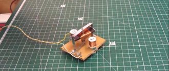
Assembling a 5 V device
A full-fledged digital device in this line without its own display is called a USB oscilloscope. Kits of component materials are sold for learning how to work with such devices. The kit includes:
- device;
- USB power cable;
- 2 probes with “crocodiles”;
- software product on disk.
Connects to PC via USB cable. The meter assembled from the kit is suitable for acquiring initial skills. In homemade circuits, such a prefix is assembled on an MMP20 microcircuit.
EDUCATIONAL GOALS FOR DCACLAB
The DCACLab is implemented for the purposes of developing and reinforcing knowledge and skills necessary for supporting mastery of objectives of the lesson. It allows the learner to apply scientific methods, respond to questions, gather the necessary materials, follow procedures, use tools and equipment, as well as draw conclusions. The virtual lab experience involves hands-on activities plus virtual experiences in a lab-like setting. This lab, therefore, provides learners with virtual experiences that engage them in a realistic manner as they maintain the integrity of similar hands-on lab activities. , the educational goals for DCACLab can be summarized in point form as follows in terms of what the learner should Thus be able to do at the end of the lab:
- Explain the basic electricity relationships.
- Create circuits out of schematic drawings.
- Make use of a voltmeter and ammeter to take circuit readings.
- Provide a logical explanation of the measurements as well as the circuit relationships.
- Explain basic electricity relationships both in parallel and series circuits.
- Develop a theory for explaining the circuit measurements.
- Find the resistance of different objects using the virtual lab.
- Discuss the charging and discharging processes of a capacitor in a circuit.
- Explain how an inductor behaves in a circuit.
ANALOG MULTIMETERStudents can experiment with this multimeter that measures Selection Knob can be used to easily set the required meter and choose from several ranges of value. Meters to choose from are:
AC Voltmeter
DC Voltmeter
Amperemeter
Ohmmeter
OSCILLOSCOPE VOLTAGE MEASUREMENT
Oscilloscope, measure time delta between two peaks
This handy oscilloscope can measure voltage by using realistic leads!
Oscilloscope measure phase shift
The oscilloscope can measure current also.
OSCILLOSCOPE TIME/DIV, VOLT/DIV SETTING
Multiple functions for each oscilloscope channel.
Students can easily observe the different settings of time base or volts/div that is found in the real oscilloscope, and can chose from multiple functions for each channel.
The oscilloscope has multiple functionalities, it can show voltage, ampere and root mean square (RMS). RMS voltage is the most common way to calculate the voltage of an AC circuit. DCAClab calculates RMS by sampling the input voltage and doing the sum-of-the-squares, simulating the high quality voltmeters, both AC meter and oscilloscope has RMS, the oscilloscope plots a dashed line to indicate the RMS.
Experiment with multiple wattmeters simultaneously.
ABCD RESISTOR COLOR BANDS
Set resistance using color bands Tolerance is randomly generated according to the selected color of band D Students can change colors of resistor and see the simulation in real time.
RESISTANCE DIRECT VALUE
Users can set resistance by writing the value and setting value unit (nano, micro, milli, kilo, mega, giga) Tune slider allows setting modifying value using (nano, micro, milli)
CIRCUIT ANALYSIS USING KIRCHHOFF CURRENT LAW
Current Animation
Easy dynamic circuit analysis for Kirchhoff’s current law
for schools sales
We are selling DCACLab through FastSpring, our payment processor. FastSpring (which is a US company) will be the vendor in the transaction and their company information will be on your invoice.
W-9 form can be downloaded here: https://www.fastspring.com/w9.pdf
10V Oscilloscopes
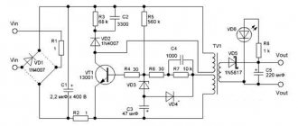
In circuits with similar voltages, closed-type resistors and a zener diode are used. Their vertical sensitivity parameters are selected up to 2 mV. When calculating the bandwidth, the maximum resistance of the device is consistent with the capacitance of the wire capacitors. Diodes are selected with a voltage of 2 V, it is advisable to select field resistors. Choosing diodes for this voltage will reduce the sampling frequency to a minimum and increase the transmission speed. Due to the rapid sweep of data, the limiting frequency drops sharply. Using a zener diode or a divider made from a modulator will help solve this problem.
10V circuit
RS232 Digital Oscilloscope for PC
Let's look at a simple solution for creating a digital computer oscilloscope. The device is based on an eight-bit PIC12F675 processor.
Circuit diagram of a digital oscilloscope for a computer
Below is a block diagram of the oscilloscope:
The processor operates at a frequency of 20 MHz. The microcontroller continuously measures the input voltage, converts it, and sends a digital value to the computer's serial port. The serial port baud rate is 115 kBit and, as shown in the following figure, data is scanned and sent at a rate of about 7.5 kHz (134 µs).
How to make a 15 V model
During assembly, linear resistors are used, the resistance of which is at the limit level - 5 MΩ. This allows the zener diode to operate in a gentle mode. When selecting capacitors, the threshold voltage is first measured by the tester.
Attention! The test results obtained, when using tuning resistors for the device, can be inaccurate. Linear resistors should be used.
When assembling, do not forget to mount a port connected through a probe to the microcircuit, while a divider is connected through the bus. The use of vacuum diodes in the assembly will allow you to control the level of oscillation amplitude.
15V Oscilloscope
Connection diagrams for PNP and NPN sensors
The difference between PNP and NPN sensors is that they switch different poles of the power source. PNP (from the word “Positive”) switches the positive output of the power supply, NPN – negative.
Below, as an example, are diagrams for connecting sensors with a transistor output. Load – as a rule, this is the controller input.
Sensor. The load (Load) is constantly connected to “minus” (0V), the supply of discrete “1” (+V) is switched by a transistor. NO or NC sensor – depends on the control circuit (Main circuit)
Sensor. The load (Load) is constantly connected to the “plus” (+V). Here, the active level (discrete “1”) at the sensor output is low (0V), while the load is supplied with power through the opened transistor.
I urge everyone not to get confused; the operation of these schemes will be described in detail below.
The diagrams below show basically the same thing. Emphasis is placed on the differences in the PNP and NPN output circuits.
Connection diagrams for NPN and PNP sensor outputs
The left figure shows a sensor with an NPN
. The common wire is switched, which in this case is the negative wire of the power source.
On the right is the case with a PNP
at the exit. This case is the most common, since in modern electronics it is customary to make the negative wire of the power supply common, and activate the inputs of controllers and other recording devices with a positive potential.
Using PPR1 series resistors
Devices containing elements of this line are very popular. Due to their high sensitivity, they are used for monitoring electrical equipment. To create this meter you will need a CRT, a pulse modulator, a rectifier and contactors with plates. The installation of a kenotron is justified by the accuracy of the readings obtained. The operational type device requires the installation of a controller.
The resistance value is not higher than 34 Ohms, and the signal conductivity is 4.2-4.5 Ohms. A USB port is connected through a low conductivity modulator. Spectral expanders for the circuit are taken of the pulse type.
Important! It is necessary to organize voltage stabilization, fix the expander next to the comparator, which will reduce heat losses.
Assembling a pocket oscilloscope based on Android
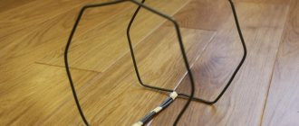
If the frequency to be measured is in the range of 20 kHz (sound audible to the ear), then use headphones with a microphone. To assemble a new device based on the Android OS, you can do without additional components. A 3.5 mm jack is taken from the headset. Probes are soldered to the microphone contacts. A measurement limit switch is inserted between them and the plug. Download the Oscilloscope application to your phone. The signal received at the microphone input will be displayed on the screen.
Measurement limits switch circuit
Pros and cons of the “android” build
There are more disadvantages to this method than advantages. Minuses:
- does not provide measurement accuracy;
- allows only high-frequency signals to be measured;
- it is impossible to measure transient processes at constant voltage;
- the gadget's input is at risk.
There are few advantages:
- 20 minutes of installation time;
- assembly is easy.
It's hard to call this attachment a good measuring device.
Inductive sensor parameters
One of the parameters has already been described above - this is the response range. Although, according to experts, it is not important, it is precisely on this basis that the choice is made. The thing is that the product passport indicates the nominal voltage parameters when the device operates at a temperature of +20C. Direct voltage is 24 volts, alternating voltage is 230 volts. As you understand, in such conditions the induction sensor usually does not work, and if it does, it rarely works. In this case, the object that will change the inductance of the device coil should be a steel plate; its width should be equal to three response ranges and 1 mm thick.
In practice, the choice is based on two response range indicators:
- Effective.
- Useful.
The readings of the first differ from the nominal parameter within ±10%. At the same time, the temperature range expands from +18C to +28C. The second is defined as ±10% of the first at a temperature range from 25 to 70C. And if with the first parameter the rated voltage in the network is used, then with the second there is a spread from 85% to 110% of the nominal.
There is one more parameter that is associated with the response zone. This is the guaranteed limit. Its lower part is “0”, and its upper part is 81% of the nominal range.
Parameters such as hysteresis and repeatability must also be taken into account. What is hysteresis in this case? Essentially, this is the distance between the farthest trigger positions of the sensor. Its optimal value is 20% of the effective response range.
Not least important is the material from which the tracking (movement) object is made. The best option is steel 37, its reduction coefficient is “1”. All other metals have a lower coefficient. For example, stainless steel – 0.85, copper – 0.3. How to understand what the reduction factor affects? Let's take a copper plate as an example. That is, it turns out that the response range will be equal to 0.3 times the useful response range. Quite a low figure.
We list other not so important parameters6
Constant voltage has ranges: 10-30, 10-60, 5-60 volts. Variable 98-253 volts.
- Load current (nominal) – 200 mA. Today, manufacturers sometimes produce sensors with a current load of 500 mA. This is the so-called special version.
- Response rate. The essence of this parameter is that it shows the maximum value of the ability to switch. This parameter is measured in hertz. So for the main industrial sensors this figure is 1000 Hz.
Assembling an oscilloscope from a tablet
It is possible to mount an oscilloscope from a laptop or tablet using the Hantek-6022BE-2-20-USB-PC attachment. The tablet is used as a monitor. Control of measurements by command - from the screen or with the mouse.
Hantek console
Software for oscilloscope on tablet and android
If you make a USB oscilloscope from a sound card yourself, download the software. The program is downloaded from the Play Market or other similar sites for downloading applications. Such programs allow you not only to achieve accurate measurements for the tablet, but also to perform the necessary signal calibration.
Wideband frequency using a separate gadget
The use of a separate device will allow you to expand the frequency range. It includes an analog to digital converter. Further pulses are sent in digital format. Measurement accuracy increases. Available as a portable device with a display.
Oscilloscope from an Android tablet
When purchasing an oscilloscope attachment, the OS selected is not “Windows”, but “Android”. The set-top box must support the following options:
- Bluetooth channel;
- data transfer using Wi-Fi.
This will allow you to do without contact connection between the gadget and the set-top box.
Bluetooth channel
Connecting via Bluetooth has limitations:
- the tested frequency has a limit of 1 MHz;
- U probe = 10 V;
- coverage area – 10 m.
This limits the resource when using these types of connections.
Transfer data using Wi-Fi
It is possible to connect an oscilloscope from a Linux tablet or another manufacturer via a wireless network - a wi-fi channel. The package of measurements is issued on the tablet without delay and for an unlimited number of project participants. The presence of a recording option allows you to work with information in offline and online versions. The connection range is higher than Bluetooth.
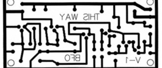
DIY USB oscilloscope circuit diagram
Using a 5 V source and connecting via a USB cable, you can assemble such a circuit yourself.
USB oscilloscope circuits
The creation of such devices independently is justified for measurements that do not require accurate results. An approach to solving the issue is to use a ready-made, full-fledged console.
Implementation
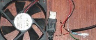
In order to build an oscilloscope, you need to assemble an attachment, which must include 8 semiconductor diodes, 3 resistors and one attenuator, a plug for connecting to a sound card (LINE-IN), everything as shown in the do-it-yourself oscilloscope diagram.
The diodes do not pass signals with an amplitude greater than 2V, and the combination of resistors connected in series to form a divider allows high input voltages.
The digital signal to be diagnosed is supplied to the input terminals of the set-top box.
The assembled circuit has a linear input to the sound card through a special plug. The length of the connecting wire is important here.
The shorter the wire, the fewer errors occur when measuring the signal, since at low measured levels there is a high probability of high distortion errors.
It is best to use a two-wire wire. The photo of a do-it-yourself oscilloscope clearly shows that a copper braided electrical wire is used.